ENGINE PERFORMANCE
2.3L
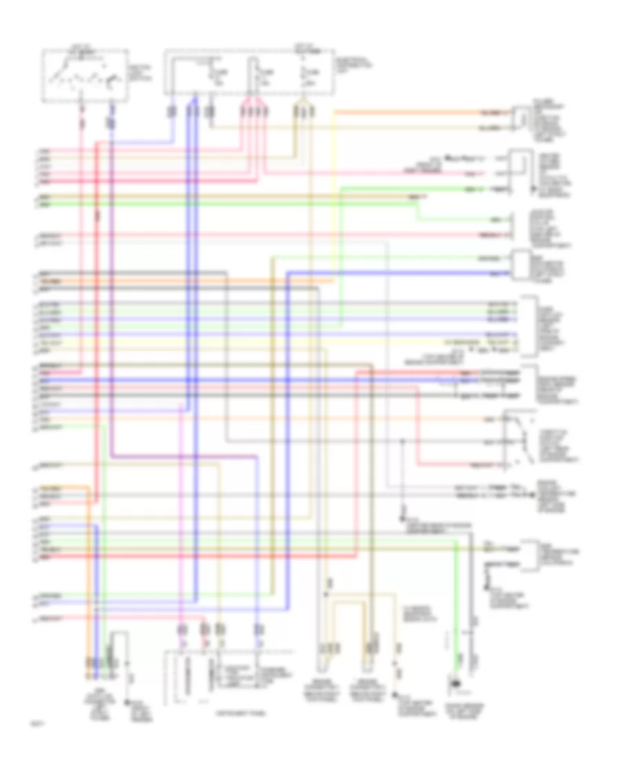
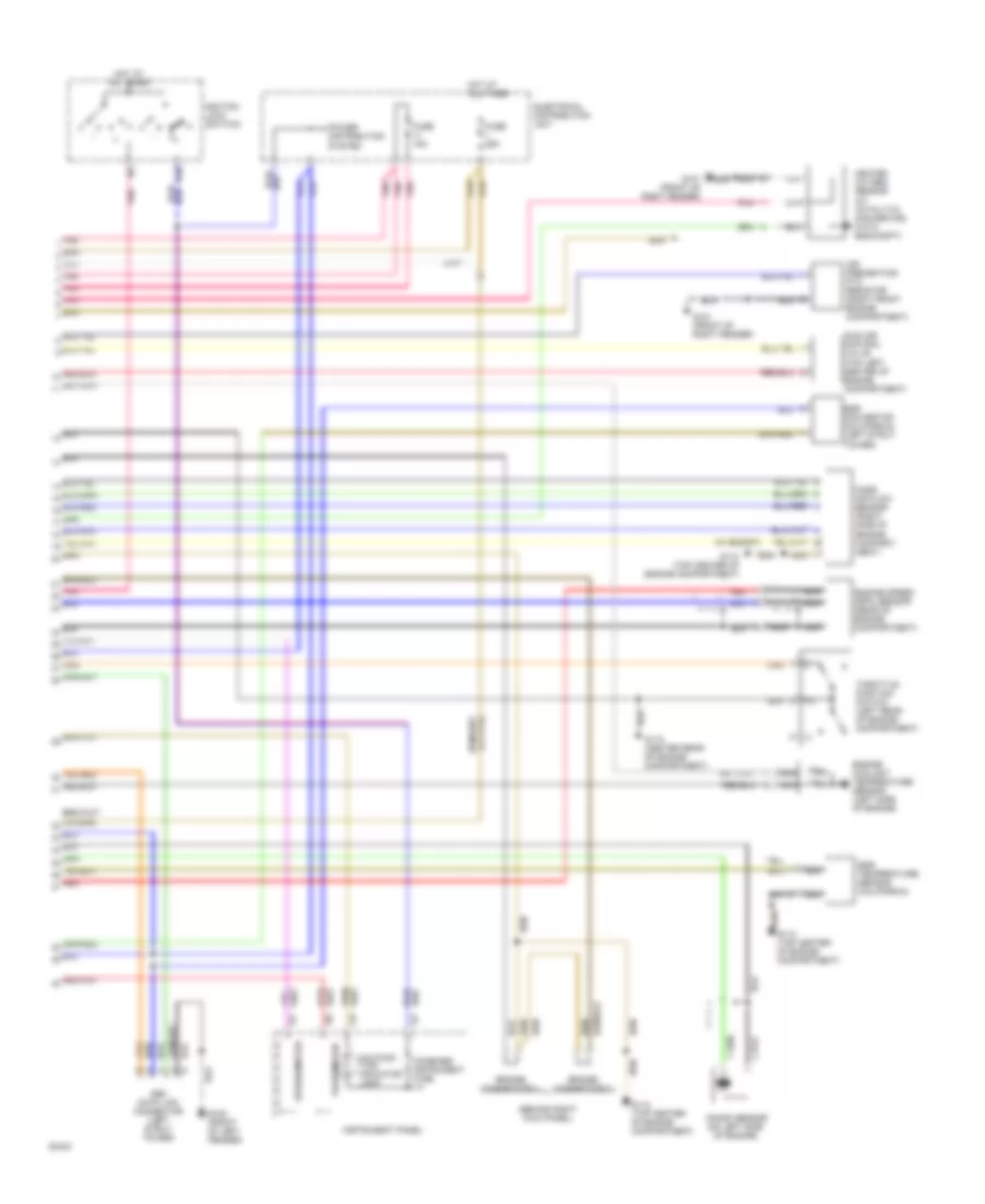
2.3L LH-Jetronic, Engine Performance Wiring Diagrams (1 of 2) for Volvo 940 Turbo 1994

List of elements for 2.3L LH-Jetronic, Engine Performance Wiring Diagrams (1 of 2) for Volvo 940 Turbo 1994:
-
- (below i/p, above steering column)
- (w/ egr, b230fd)
- (with b200/ b230g)
- A/c high pressure sensor
- A/c solenoid coupling
- Battery
- Bus
- Cooling fans system
- Distributor
- Ecc control module
- Electrical distribution unit
- Engine cooling fan relay
- Ez-k (di) system control module
- Ez-k (di) system power amplifier (left front corner of engine compartment)
- Fuel injection relay
- Fuel level sensor/ primer
- Fuel pump (rear of engine compart- ment)
- G112 (top center of engine compartment)
- G115 center rear of engine compart- ment)
- G203 (right kick panel)
- G408 (sedan) (at trunk opening)
- G999 (wagon) (at tail light)
- High-speed pressure sensor
- Ignition coil (right rear corner of engine compartment)
- Injection valves
- Lh-jetronic 2.4 (mfi) system control module (behind right kick panel)
- Low-speed pressure sensor
- Mcc a/c controls
- Nca
- Pin b1
- Pin b2
- Pnk
- Pump (in fuel tank)
- Radio interference suppression relay (right front engine compartment)
- Red
- Red/
- Service data link connector (for starter motor)
- Starter motor
- W/ electronic climate control
- W/ manual climate control
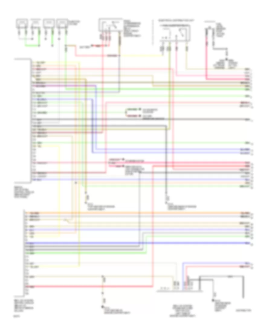
2.3L LH-Jetronic, Engine Performance Wiring Diagrams (2 of 2) for Volvo 940 Turbo 1994
List of elements for 2.3L LH-Jetronic, Engine Performance Wiring Diagrams (2 of 2) for Volvo 940 Turbo 1994:
- (behind right kick panel)
- (w/ b200/230g)
- * w/ b200fg, b230f/fb/g, b230fd auto
- 15r
- Bridge connector 1
- Bridge connector 2
- Combined instrument fuse
- Egr convertor (california) (left strut tower)
- Egr temperature sensor (california)
- Electrical distribution unit
- Engine coolant temperature sensor (left side of engine)
- Engine speed (rpm) sensor (rear of engine compartment)
- Fuse 15a
- Fuse 25a
- G100 (front of left fender)
- G101 (front of right fender)
- G112 (top center of engine compartment)
- G115 (center rear of engine compartment)
- Heated oxygen sensor (at catalytic convertor) (w/ b200f, b230f/fb/fd)
- Hot at all times
- Idle air control valve (top left center of engine compartment)
- Ignition lock (switch)
- Iii
- Instrument panel
- Knock sensor (on left side of engine)
- Malfunc- tion indicator lamp
- Mass air flow sensor (left side of engine compart- ment)
- Nca
- Obd data link connector (left strut tower)
- Pnk
- Pulsed secondary air injection solenoid (w/ b230fd) (left strut tower)
- Red
- Speedometer
- Tachometer
- Throttle position switch (left rear of engine compartment)
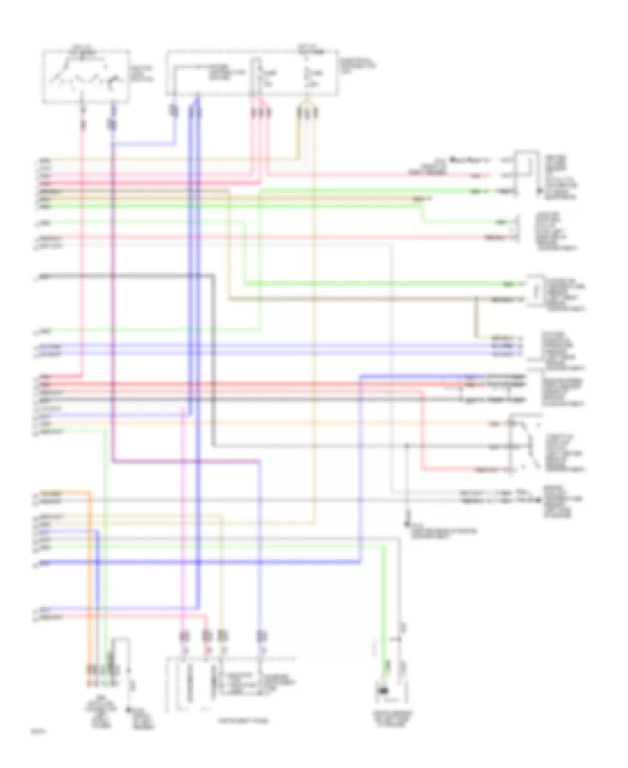
2.3L Regina, Engine Performance Wiring Diagrams (1 of 2) for Volvo 940 Turbo 1994
List of elements for 2.3L Regina, Engine Performance Wiring Diagrams (1 of 2) for Volvo 940 Turbo 1994:
-
- (below i/p, above steering column)
- (left side of engine compartment)
- A/c high pressure sensor
- A/c solenoid coupling
- Battery
- Distributor
- Electrical distribution unit
- Fuel injection relay
- Fuel level sensor/ pump (in fuel tank)
- G112 (top center of engine compartment)
- G115 center rear of engine compart- ment)
- G408 (sedan) (at trunk opening)
- G999 (wagon) (at tail light)
- Injection valves
- Nca
- Pnk
- Radio interference suppression relay (right front engine compartment)
- Red
- Red/
- Regina (mfi) system control module (behind right kick panel)
- Rex-i (di) system control module
- Rex-i (di) system power amplifier/ ignition coil
- Service data link connector (for starter motor)
- Starter motor
2.3L Regina, Engine Performance Wiring Diagrams (2 of 2) for Volvo 940 Turbo 1994
List of elements for 2.3L Regina, Engine Performance Wiring Diagrams (2 of 2) for Volvo 940 Turbo 1994:
- 15r
- Combined instrument fuse
- Electrical distribution unit
- Engine coolant temperature sensor (left side of engine)
- Engine speed (rpm) sensor (rear of engine compartment)
- Fuse 15a
- Fuse 25a
- G100 (front of left fender)
- G101 (front of right fender)
- G115 (center rear of engine compartment)
- Heated oxygen sensor (at catalytic convertor) (w/ b200f, b230f/fb/fd)
- Hot at all times
- Idle air control valve (top left center of engine compartment)
- Ignition lock (switch)
- Iii
- Instrument panel
- Intake air temperature sensor (left front engine compartment)
- Intake manifold pressure sensor (left rear engine compartment)
- Knock sensor (on left side of engine)
- Malfunc- tion indicator lamp
- Nca
- Obd data link connector (left strut tower)
- Pnk
- Power distribution system
- Red
- Speedometer
- Tachometer
- Throttle position switch (left center rear of engine compartment)
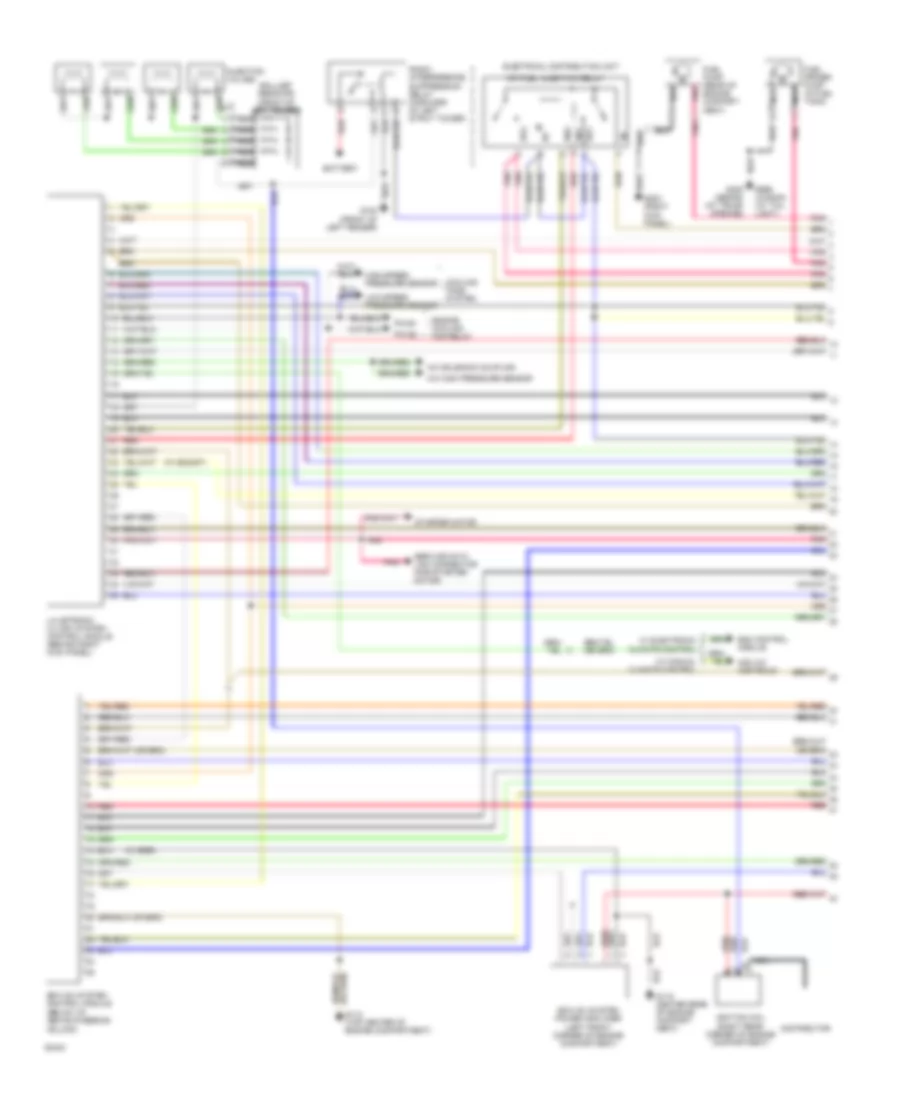
2.3L Turbo, Engine Performance Wiring Diagrams (1 of 2) for Volvo 940 Turbo 1994
List of elements for 2.3L Turbo, Engine Performance Wiring Diagrams (1 of 2) for Volvo 940 Turbo 1994:
- (below i/p, above steering column)
- (w/ b230gt)
- (w/ egr)
- 86/1
- 86/2
- 87/1
- 87/2
- A/c high pressure sensor
- A/c solenoid coupling
- Ballast resistor (front of left fender)
- Battery
- Bus
- Cooling fans system
- Distributor
- Ecc control module
- Electrical distribution unit
- Engine cooling fan relay
- Ez-k (di) system control module
- Ez-k (di) system power amplifier (left front corner of engine compartment)
- Fuel primer pump (in fuel tank)
- Fuel pump (rear of engine compart- ment)
- G100 (front of left fender)
- G112 (top center of engine compartment)
- G115 center rear of engine compart- ment)
- G203 (right kick panel)
- G408 (sedan) (at trunk opening)
- G999 (wagon) (at tail light)
- High-speed pressure sensor
- Ignition coil (right rear corner of engine compartment)
- Injection valves
- Lh-jetronic 2.4 (mfi) system control module (behind right kick panel)
- Low-speed pressure sensor
- Mcc a/c controls
- Mfi fuel injection relay
- Nca
- Pin b1
- Pin b2
- Pnk
- Radio interference suppression relay (forward of left strut tower)
- Red
- Service data link connector (for starter motor)
- Starter motor
- W/ electronic climate control
- W/ manual climate control
2.3L Turbo, Engine Performance Wiring Diagrams (2 of 2) for Volvo 940 Turbo 1994
List of elements for 2.3L Turbo, Engine Performance Wiring Diagrams (2 of 2) for Volvo 940 Turbo 1994:
- (behind right kick panel)
- (w/ b230gt)
- 15r
- Air preheating ptc resistor (right front engine compartment)
- Bridge connector 1
- Bridge connector 2
- Combined instrument fuse
- Egr convertor (california) (left strut tower)
- Egr temperature sensor (california)
- Electrical distribution unit
- Engine coolant temperature sensor (left side of engine)
- Engine speed (rpm) sensor (rear of engine compartment)
- Fuse 15a
- Fuse 25a
- G100 (front of left fender)
- G101 (front of right fender)
- G112 (top center of engine compartment)
- G115 (center rear of engine compartment)
- Heated oxygen sensor (at catalytic convertor) (with b200/230ft)
- Hot at all times
- Idle air control valve (top left center of engine compartment)
- Ignition lock (switch)
- Iii
- Instrument panel
- Knock sensor (on left side of engine)
- Malfunc- tion indicator lamp
- Mass air flow sensor (right side of engine compart- ment)
- Nca
- Obd data link connector (left strut tower)
- Pnk
- Power distribution system
- Red
- Speedometer
- Tachometer
- Throttle position switch (left rear of engine compartment)