ENGINE PERFORMANCE
2.5L TURBO
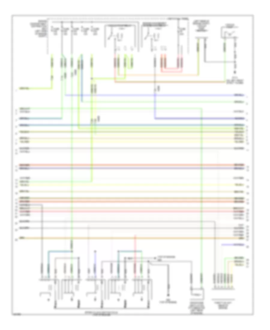
2.5L Turbo, Engine Performance Wiring Diagram (1 of 4) for Volvo C30 T-5 2012

List of elements for 2.5L Turbo, Engine Performance Wiring Diagram (1 of 4) for Volvo C30 T-5 2012:
- (on top front of engine) variable valve timing intake solenoid
- (on top rear of engine, in air duct) mass airflow (maf) sensor
- (top of engine) injection valves
- A10
- A11
- A12
- A13
- A14
- A15
- A16
- A17
- A18
- A19
- A20
- A21
- A22
- A23
- A24
- A25
- A26
- A27
- A28
- A29
- A30
- A31
- A32
- A33
- A34
- A35
- A36
- A37
- A38
- A39
- A40
- A41
- A42
- A43
- A44
- A45
- A46
- A47
- A48
- A49
- A50
- A51
- Coolant temperature sensor (front of engine compt)
- Engine control module (ecm) (left front of engine compt)
- Evap valve (at right rear of engine)
- Intake manifold pressure & temperature sensor (right front of engine compt)
- Nca
- Oil level sensor (in oil pan)
- Oil pressure monitor (lower left side of engine)
- Rear heated oxygen sensor (downstream of catalytic converter)
- Starting/ charging system
- Turbocharger control valve (right side of engine)
2.5L Turbo, Engine Performance Wiring Diagram (2 of 4) for Volvo C30 T-5 2012
List of elements for 2.5L Turbo, Engine Performance Wiring Diagram (2 of 4) for Volvo C30 T-5 2012:
- (left rear of engine compt) vacuum pump switch
- (on left front strut tower)
- (top of engine)
- 64/90
- Crankcase ventilation ptc resistor (left rear of engine)
- Engine compartment distribution box (left side of engine compt)
- Engine management system main relay
- Fuse f32 10a
- Fuse f33 20a
- Fuse f34 10a
- Fuse f35 15a
- Fuse f36 10a
- Fuse f9 30a
- G114
- G88 (top of engine)
- G89
- Hot at all times
- Nca
- Spark plug & ignition coils (top of engine)
- Throttle unit (rear of engine)
- Vacuum pump
- Vacuum pump relay
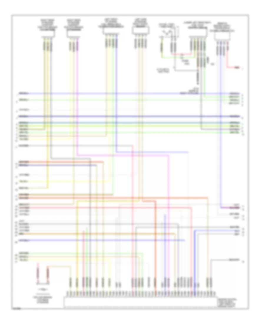
2.5L Turbo, Engine Performance Wiring Diagram (3 of 4) for Volvo C30 T-5 2012
List of elements for 2.5L Turbo, Engine Performance Wiring Diagram (3 of 4) for Volvo C30 T-5 2012:
- (c30)
- (in fuel tank) fuel pump
- (left front of engine) fuel pressure & temperature sensor
- (left side of engine) front knock sensor
- (rear of engine compt) transmission control module (tcm)
- (right rear of engine) camshaft position sensor (intake side)
- (right rear of engine) camshaft position sensor (outlet side)
- (under left rear seat) fuel pump control module
- 64/956
- A52
- A53
- A54
- A55
- A56
- A57
- A58
- A59
- A60
- A61
- A62
- A63
- A64
- A65
- A66
- A67
- A68
- A69
- A70
- A71
- A72
- A73
- A74
- A75
- A76
- A77
- A78
- A79
- A80
- A81
- A82
- A83
- A84
- A85
- A86
- A87
- A88
- A89
- A90
- A91
- A92
- A93
- A94
- A95
- A96
- A97
- C30
- Engine control module (ecm) (left front of engine compt)
- G116 (base of right "a" pillar)
- Impulse sensor (top rear of engine)
- Red
- W/ plastic gas tank
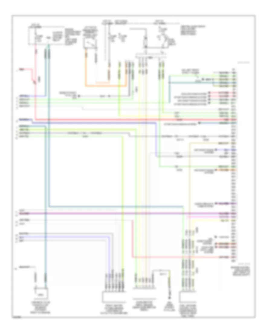
2.5L Turbo, Engine Performance Wiring Diagram (4 of 4) for Volvo C30 T-5 2012
List of elements for 2.5L Turbo, Engine Performance Wiring Diagram (4 of 4) for Volvo C30 T-5 2012:
- (at top of brake pedal assembly) brake light contact
- (base of right "a" pillar) g10
- (on left front strut tower)
- 63/90
- 64/111
- 64/113
- 64/51
- 64/90
- A10
- A28
- Accelerator pedal sensor (near accelerator pedal)
- Air conditioning system
- B10
- B11
- B12
- B13
- B14
- B15
- B16
- B17
- B18
- B19
- B20
- B21
- B22
- B23
- B24
- B25
- B26
- B27
- B28
- B29
- B30
- B31
- B32
- B33
- B34
- B35
- B36
- B37
- B38
- B39
- B40
- B41
- B42
- B43
- B44
- B45
- B46
- B47
- B48
- B49
- B50
- B51
- B52
- B53
- B54
- B55
- B56
- B57
- B58
- C16
- Cem
- Central electronic module (cem) (behind right side of dash)
- Climate control system relay
- Computer data lines system
- Cooling fans system
- E10
- E28
- E40
- E41
- Engine compartment distribution box (left side of engine compt)
- Engine control module (ecm) (left front of engine compt)
- Front heated oxygen sensor (upstream of catalytic converter)
- Fuel leakage control pump (under rear of vehicle, near fuel tank)
- Fuel pump relay
- Fuse f23 10a
- Fuse f44 10a
- Fuse f57 15a
- Fuse f74 15a
- G132
- G22
- G31
- G84 (base of right "a" pillar)
- Hot at all times
- Hot in run or start
- Nca
- Red
- Starting/charging system
- Variable valve timing outlet solenoid (top right front of engine)