ENGINE PERFORMANCE
2.3L
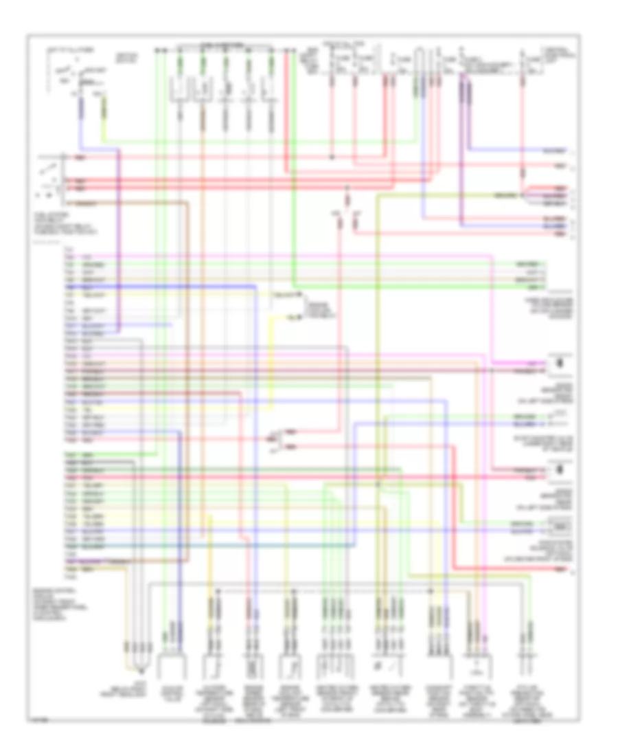
2.3L Turbo, Engine Performance Wiring Diagrams (1 of 2) for Volvo S70 T-5 1998

List of elements for 2.3L Turbo, Engine Performance Wiring Diagrams (1 of 2) for Volvo S70 T-5 1998:
- (non-convert.) (convert.)
- (rear) (on left side of eng)
- 15a
- A/t
- A10
- A11
- A12
- A13
- A14
- A15
- A16
- A17
- A18
- A19
- A20
- A21
- A22
- A23
- A24
- A25
- A26
- A27
- A28
- A29
- A30
- A31
- A32
- A33
- A34
- A35
- A36
- A37
- A38
- A39
- A40
- A41
- A42
- A43
- Acc
- Camshaft position sensor (on right rear of eng)
- Central electrical unit
- Eng compt. relay/ fuse box
- Engine control module (on right front inner fender panel, in control module box)
- Engine coolant temperature sensor (left front of eng)
- Engine cooling fan relay
- Engine speed sensor (rear of of eng, above bellhousing)
- Evap canister valve (under right rear of vehicle)
- Fuel injectors
- Fuel system main relay (on eng compt relay/ fuse box, position no1)
- Fuse 10a
- Fuse 3 20a 15a
- Fuse 50a
- Fuse 60a
- G107 (below right front headlamp)
- Heated oxygen sensor (front) (in front of catalytic converter)
- Heated oxygen sensor (rear) (behind catalytic converter)
- Hot at all times
- Hot at all tims
- Idle air control valve
- Ignition switch
- Knock sensor (ks)
- Knock sensor (ks) (front) (on left side of eng)
- M/t
- Mass air flow/air volume sensor (on air cleaner housing)
- Nca
- Off
- Outside temperature sensor (optional) (on right side of hvac housing)
- Pair system solenoid valve (optional) (on center front of eng)
- Pnk
- Ptc air preheating resistor (optional) (on fresh air intake hose, near air filter)
- Red
- Run
- Start
- Throttle position (tp) sensor (on throttle body assembly)
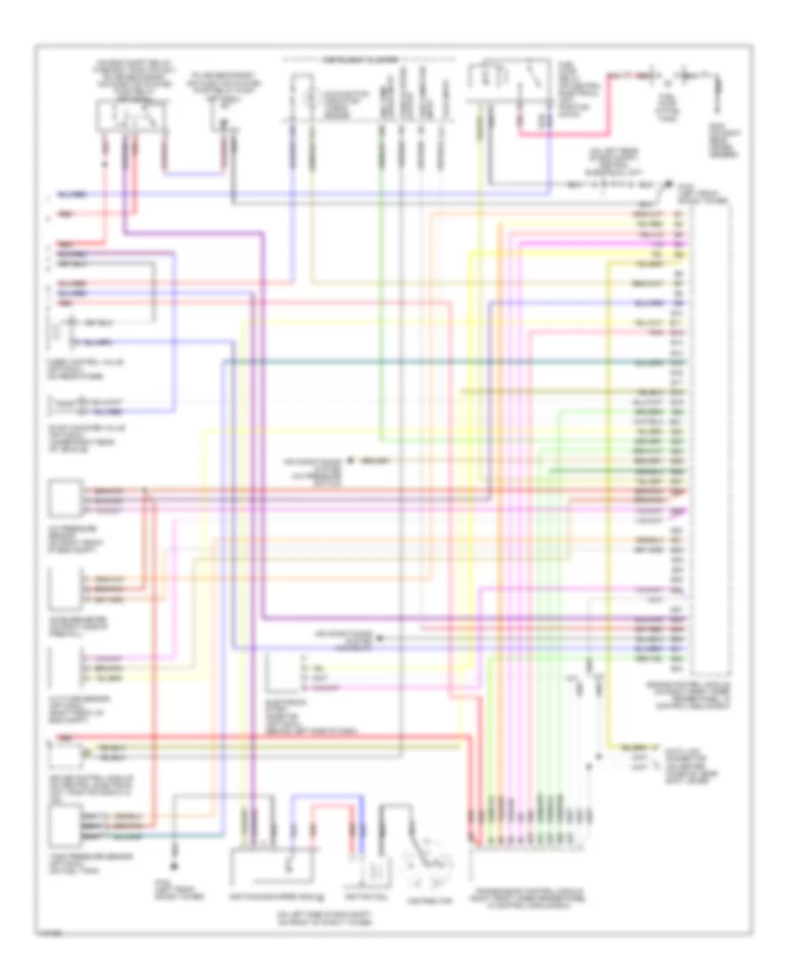
2.3L Turbo, Engine Performance Wiring Diagrams (2 of 2) for Volvo S70 T-5 1998
List of elements for 2.3L Turbo, Engine Performance Wiring Diagrams (2 of 2) for Volvo S70 T-5 1998:
- (on eng compt relay/ fuse box, position no1) pulse secondary air injection system pump relay (optional)
- (on left rear of eng compt) central electrical unit
- (on left side of eng compt, on front of strut tower)
- (optional)
- A/c pressure sensor (on right front of eng compt)
- A/t
- A10
- A11
- A18
- A26
- Accelerometer (on right side of firewall)
- Air conditioning system (a/c pressure switch)
- Air conditioning system (a/c relay)
- Altitude sensor (optional) (right front of eng compt)
- B10
- B11
- B12
- B13
- B14
- B15
- B16
- B17
- B18
- B19
- B20
- B21
- B22
- B23
- B24
- B25
- B26
- B27
- B28
- B29
- B30
- B31
- B32
- B33
- B34
- B35
- B36
- B37
- B38
- B39
- B40
- B41
- B42
- B43
- Cruise control module (on central electrical unit, position nos101 & 102)
- Data link connector (on center console, near shift lever)
- Distributor
- Electronic start inhibitor (optional) (behind left side of dash)
- Eng temp gauge input
- Engine control module (on right front inner fender panel, in control module box)
- Evap canister valve (optional) (under right rear of vehicle)
- Fuel pump (in fuel tank)
- Fuel pump relay (on central electrical unit, position no103)
- G102 (left front shock tower)
- G303 (on right rear cross- member)
- Igniti0n coil
- Ignition discharge module
- Input trip computer
- Instrument cluster
- Malfunction indicator "check engine"
- Nca
- Pnk
- Pulse secondary air injection system pump relay pump
- Red
- Tach input
- Tank pressure sensor (optional) (on fuel tank)
- Transmission control module (right front inner fender panel, in control module box)
- Turbo control valve (optional) (on rear of eng)
- Vehicle speed output
2.4L
2.4L Turbo, Engine Performance Wiring Diagrams (1 of 2) for Volvo S70 T-5 1998
List of elements for 2.4L Turbo, Engine Performance Wiring Diagrams (1 of 2) for Volvo S70 T-5 1998:
- (non-convert.) (convert.)
- (rear) (on left side of eng)
- 15a
- A/t
- A10
- A11
- A12
- A13
- A14
- A15
- A16
- A17
- A18
- A19
- A20
- A21
- A22
- A23
- A24
- A25
- A26
- A27
- A28
- A29
- A30
- A31
- A32
- A33
- A34
- A35
- A36
- A37
- A38
- A39
- A40
- A41
- A42
- A43
- Acc
- Camshaft position sensor (on right rear of eng)
- Central electrical unit
- Eng compt. relay/ fuse box
- Engine control module (on right front inner fender panel, in control module box)
- Engine coolant temperature sensor (left front of eng)
- Engine cooling fan relay
- Engine speed sensor (rear of of eng, above bellhousing)
- Evap canister valve (under right rear of vehicle)
- Fuel injectors
- Fuel system main relay (on eng compt relay/ fuse box, position no1)
- Fuse 10a
- Fuse 3 20a 15a
- Fuse 50a
- Fuse 60a
- G107 (below right front headlamp)
- Heated oxygen sensor (front) (in front of catalytic converter)
- Heated oxygen sensor (rear) (behind catalytic converter)
- Hot at all times
- Hot at all tims
- Idle air control valve
- Ignition switch
- Knock sensor (ks)
- Knock sensor (ks) (front) (on left side of eng)
- M/t
- Mass air flow/air volume sensor (on air cleaner housing)
- Nca
- Off
- Outside temperature sensor (optional) (on right side of hvac housing)
- Pair system solenoid valve (optional) (on center front of eng)
- Pnk
- Ptc air preheating resistor (optional) (on fresh air intake hose, near air filter)
- Red
- Run
- Start
- Throttle position (tp) sensor (on throttle body assembly)
2.4L Turbo, Engine Performance Wiring Diagrams (2 of 2) for Volvo S70 T-5 1998
List of elements for 2.4L Turbo, Engine Performance Wiring Diagrams (2 of 2) for Volvo S70 T-5 1998:
- (on eng compt relay/ fuse box, position no1) pulse secondary air injection system pump relay (optional)
- (on left rear of eng compt) central electrical unit
- (on left side of eng compt, on front of strut tower)
- (optional)
- A/c pressure sensor (on right front of eng compt)
- A/t
- A10
- A11
- A18
- A26
- Accelerometer (on right side of firewall)
- Air conditioning system (a/c pressure switch)
- Air conditioning system (a/c relay)
- Altitude sensor (optional) (right front of eng compt)
- B10
- B11
- B12
- B13
- B14
- B15
- B16
- B17
- B18
- B19
- B20
- B21
- B22
- B23
- B24
- B25
- B26
- B27
- B28
- B29
- B30
- B31
- B32
- B33
- B34
- B35
- B36
- B37
- B38
- B39
- B40
- B41
- B42
- B43
- Cruise control module (on central electrical unit, position nos101 & 102)
- Data link connector (on center console, near shift lever)
- Distributor
- Electronic start inhibitor (optional) (behind left side of dash)
- Eng temp gauge input
- Engine control module (on right front inner fender panel, in control module box)
- Evap canister valve (optional) (under right rear of vehicle)
- Fuel pump (in fuel tank)
- Fuel pump relay (on central electrical unit, position no103)
- G102 (left front shock tower)
- G303 (on right rear cross- member)
- Igniti0n coil
- Ignition discharge module
- Input trip computer
- Instrument cluster
- Malfunction indicator "check engine"
- Nca
- Pnk
- Pulse secondary air injection system pump relay pump
- Red
- Tach input
- Tank pressure sensor (optional) (on fuel tank)
- Transmission control module (right front inner fender panel, in control module box)
- Turbo control valve (optional) (on rear of eng)
- Vehicle speed output
2.4L, Engine Performance Wiring Diagrams (1 of 2) for Volvo S70 T-5 1998
List of elements for 2.4L, Engine Performance Wiring Diagrams (1 of 2) for Volvo S70 T-5 1998:
- (non-convert.) (convert.)
- (rear) (on left side of eng)
- 15a
- A/t
- A10
- A11
- A12
- A13
- A14
- A15
- A16
- A17
- A18
- A19
- A20
- A21
- A22
- A23
- A24
- A25
- A26
- A27
- A28
- A29
- A30
- A31
- A32
- A33
- A34
- A35
- A36
- A37
- A38
- A39
- A40
- A41
- A42
- A43
- Acc
- Camshaft position sensor (on right rear of eng)
- Central electrical unit
- Eng compt. relay/ fuse box
- Engine control module (on right front inner fender panel, in control module box)
- Engine coolant temperature sensor (left front of eng)
- Engine cooling fan relay
- Engine speed sensor (rear of of eng, above bellhousing)
- Evap canister valve (under right rear of vehicle)
- Fuel injectors
- Fuel system main relay (on eng compt relay/ fuse box, position no1)
- Fuse 10a
- Fuse 3 20a 15a
- Fuse 50a
- Fuse 60a
- G107 (below right front headlamp)
- Heated oxygen sensor (front) (in front of catalytic converter)
- Heated oxygen sensor (rear) (behind catalytic converter)
- Hot at all times
- Hot at all tims
- Idle air control valve
- Ignition switch
- Knock sensor (ks)
- Knock sensor (ks) (front) (on left side of eng)
- M/t
- Mass air flow/air volume sensor (on air cleaner housing)
- Nca
- Off
- Outside temperature sensor (optional) (on right side of hvac housing)
- Pair system solenoid valve (optional) (on center front of eng)
- Pnk
- Ptc air preheating resistor (optional) (on fresh air intake hose, near air filter)
- Red
- Run
- Start
- Throttle position (tp) sensor (on throttle body assembly)
2.4L, Engine Performance Wiring Diagrams (2 of 2) for Volvo S70 T-5 1998
List of elements for 2.4L, Engine Performance Wiring Diagrams (2 of 2) for Volvo S70 T-5 1998:
- (on eng compt relay/ fuse box, position no1) pulse secondary air injection system pump relay (optional)
- (on left rear of eng compt) central electrical unit
- (on left side of eng compt, on front of strut tower)
- (optional)
- A/c pressure sensor (on right front of eng compt)
- A/t
- A10
- A11
- A18
- A26
- Accelerometer (on right side of firewall)
- Air conditioning system (a/c pressure switch)
- Air conditioning system (a/c relay)
- Altitude sensor (optional) (right front of eng compt)
- B10
- B11
- B12
- B13
- B14
- B15
- B16
- B17
- B18
- B19
- B20
- B21
- B22
- B23
- B24
- B25
- B26
- B27
- B28
- B29
- B30
- B31
- B32
- B33
- B34
- B35
- B36
- B37
- B38
- B39
- B40
- B41
- B42
- B43
- Cruise control module (on central electrical unit, position nos101 & 102)
- Data link connector (on center console, near shift lever)
- Distributor
- Electronic start inhibitor (optional) (behind left side of dash)
- Eng temp gauge input
- Engine control module (on right front inner fender panel, in control module box)
- Evap canister valve (optional) (under right rear of vehicle)
- Fuel pump (in fuel tank)
- Fuel pump relay (on central electrical unit, position no103)
- G102 (left front shock tower)
- G303 (on right rear cross- member)
- Igniti0n coil
- Ignition discharge module
- Input trip computer
- Instrument cluster
- Malfunction indicator "check engine"
- Nca
- Pnk
- Pulse secondary air injection system pump relay pump
- Red
- Tach input
- Tank pressure sensor (optional) (on fuel tank)
- Transmission control module (right front inner fender panel, in control module box)
- Turbo control valve (optional) (on rear of eng)
- Vehicle speed output