ENGINE PERFORMANCE
2.5L TURBO
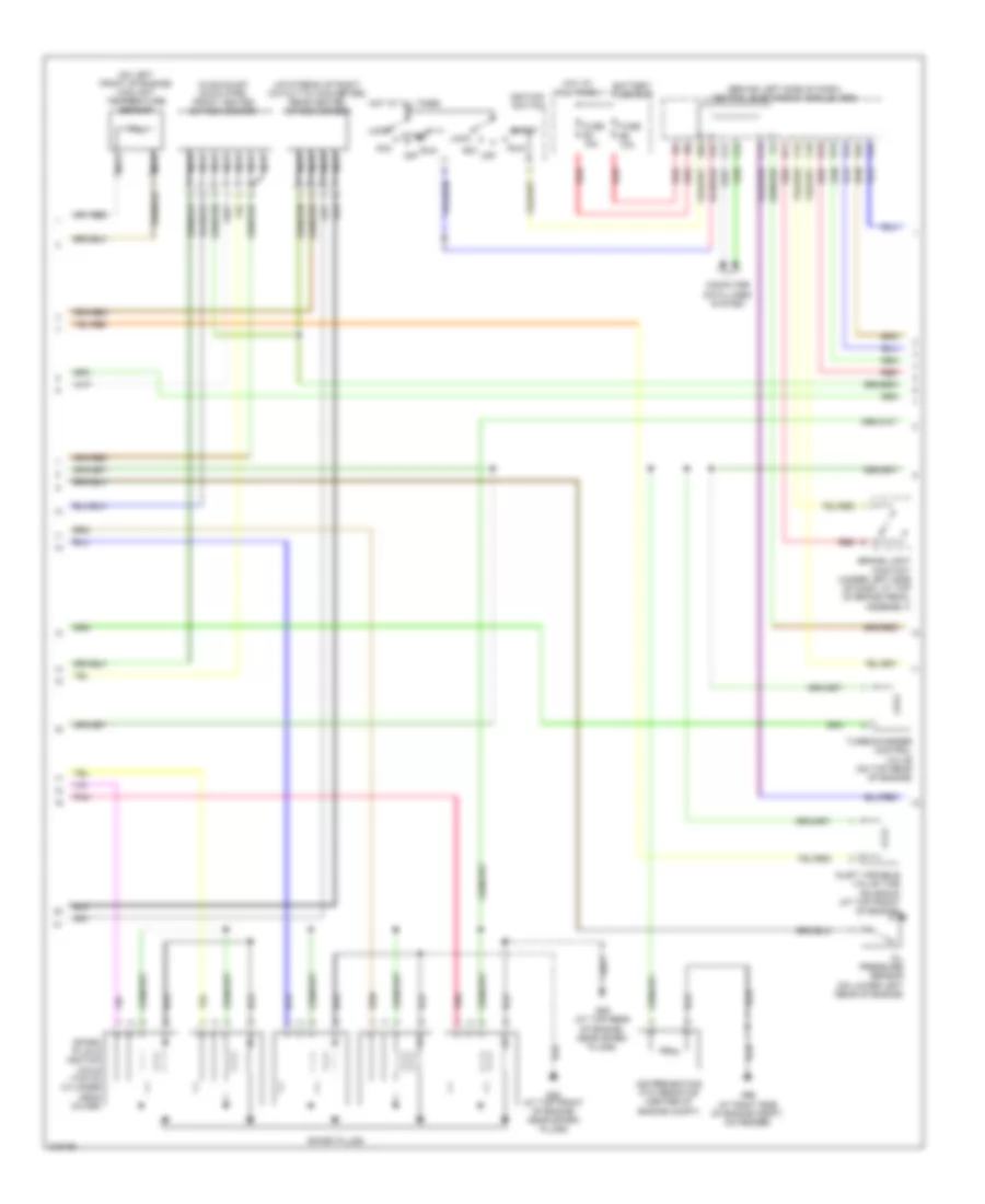
2.5L Turbo, Engine Performance Wiring Diagram (1 of 3) for Volvo S80 T-6 Premier 2005

List of elements for 2.5L Turbo, Engine Performance Wiring Diagram (1 of 3) for Volvo S80 T-6 Premier 2005:
- (at left side of engine in intake manifold) intake manifold pressure sensor
- (at left side of engine) oil level sensor
- (at rear of engine on air intake) mass airflow (maf) sensor
- (at right front of engine compt) climate control system pressure sensor
- A10
- A11
- A12
- A13
- A14
- A15
- A16
- A17
- A18
- A19
- A20
- A21
- A22
- A23
- A24
- A25
- A26
- A27
- A28
- A29
- A30
- A31
- A32
- A33
- A34
- A35
- A36
- A37
- A38
- A39
- A40
- A41
- A42
- A43
- A44
- A45
- A46
- A47
- A48
- A49
- A50
- A51
- A52
- A53
- A54
- A55
- A56
- A57
- A58
- A59
- A60
- A61
- A62
- A63
- A64
- A65
- A66
- A67
- A68
- A69
- A70
- Computer data lines system
- Cooling fans system
- Engine control module (at right side of engine compt, forward of strut tower)
- Engine throttle body (on top of throttle body assembly)
- Evap valve (at left front of engine compt)
- Exhaust side camshaft position sensor (at rear of engine)
- Front knock sensor (at top left front of engine)
- Fuel injectors (top of engine)
- G96 (at right side of engine compt, on fender)
- Impulse sensor (gasoline) (at rear of engine)
- Intake side camshaft position sensor (on top rear of engine)
- Nca
- Pnk
- Pressure & temperature sensor (rear of engine)
- Rear knock sensor (at top left rear of engine)
- Red
- Variable valve timing outlet solenoid (top front of engine)
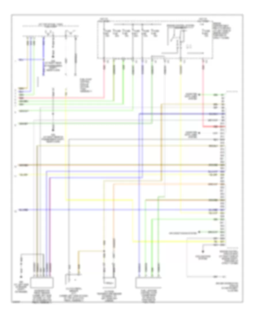
2.5L Turbo, Engine Performance Wiring Diagram (2 of 3) for Volvo S80 T-6 Premier 2005
List of elements for 2.5L Turbo, Engine Performance Wiring Diagram (2 of 3) for Volvo S80 T-6 Premier 2005:
- (behind left side of dash) central electronic module (cem)
- (in exhaust down pipe) front heated oxygen sensor
- (on left front of engine) coolant temperature sensor
- (up stream of right catalytic converter) rear heated oxygen sensor
- A16
- Acc
- Air preheating ptc resistor (center of engine compt)
- B11
- B16
- Battery fuse box
- Brake light contact (under left side of dash, at top of brake pedal assembly)
- C14
- C21
- C22
- C34
- C35
- Computer data lines system
- D16
- D43
- D44
- D45
- D60
- Fuse e4 15a
- Fuse e5 10a
- G88 (at top front of engine, near spark plugs)
- G89 (at top rear of engine, near spark plugs)
- G96 (at right side of engine compt, on fender)
- Hot at all times
- Ignition switch
- Inlet variable valve time solenoid (at top front of engine)
- Lock
- Nca
- Off
- Oil pressure sensor (on lower left rear of engine)
- Pnk
- Red
- Run
- Spark plug & ignition coils (top of cylinder head cover)
- Spark plugs
- Start
- Turbocharger control valve (on top rear of engine)
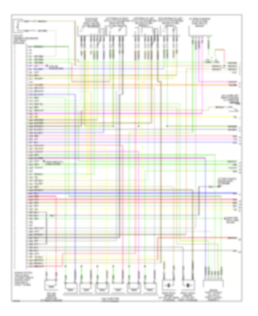
2.5L Turbo, Engine Performance Wiring Diagram (3 of 3) for Volvo S80 T-6 Premier 2005
List of elements for 2.5L Turbo, Engine Performance Wiring Diagram (3 of 3) for Volvo S80 T-6 Premier 2005:
- (at top of fuel tank) fuel pump
- Accelerator pedal sensor (under left side of dash, at top of accelerator pedal assembly)
- Air conditioning system
- B10
- B11
- B12
- B13
- B14
- B15
- B16
- B17
- B18
- B19
- B20
- B21
- B22
- B23
- B24
- B25
- B26
- B27
- B28
- B29
- B30
- B31
- B32
- B33
- B34
- B35
- B36
- B37
- B38
- B39
- B40
- B41
- B42
- B43
- B44
- B45
- B46
- B47
- B48
- Clutch pedal sensor (m/t) (under left side of dash, at top of clutch pedal assembly)
- Computer data lines system
- Cooling fans system
- Driver information module (in instrument cluster)
- Engine compartment relay/fuse box (at left side of engine compt, forward of strut tower)
- Engine control module (ecm) (at right side of engine compt, forward of strut tower)
- Engine control system main relay
- Fuel leakage control pump (under rear of vehicle, forward of fuel tank)
- Fuel pump control module (on fuel tank assembly)
- Fuse b11 20a
- Fuse b21 15a
- Fuse b23 10a
- Fuse b4 20a
- Fuse b5 15a
- Fuse b6 15a
- Fuse b8 10a
- G48 (at right rear
- G48 (at right rear of passenger's compt, near floor)
- G93 (at left side of engine compt, on fender)
- Hot at all times
- Nca
- Of passenger's compt, near floor)
- Outside temperature sensor (integral to left sideview mirror)
- Red
2.9L
2.9L, Engine Performance Wiring Diagram (1 of 3) for Volvo S80 T-6 Premier 2005
List of elements for 2.9L, Engine Performance Wiring Diagram (1 of 3) for Volvo S80 T-6 Premier 2005:
- (at rear of engine on air intake) mass airflow sensor
- (at right side of engine compt, on fender) g96
- (downstream of left catalytic converter) heated oxygen sensor 4
- (in exhaust down pipe) front heated oxygen sensor
- (on lower left rear of engine) oil pressure sensor
- (up stream of right catalytic converter) rear heated oxygen sensor
- (upstream of left catalytic converter) heated oxygen sensor 3
- A10
- A11
- A12
- A13
- A14
- A15
- A16
- A17
- A18
- A19
- A20
- A21
- A22
- A23
- A24
- A25
- A26
- A27
- A28
- A29
- A30
- A31
- A32
- A33
- A34
- A35
- A36
- A37
- A38
- A39
- A40
- A41
- A42
- A43
- A44
- A45
- A46
- A47
- A48
- A49
- A50
- A51
- A52
- A53
- A54
- A55
- A56
- A57
- A58
- A59
- A60
- A61
- A62
- A63
- A64
- A65
- A66
- A67
- A68
- A69
- A70
- Computer data lines system
- Coolant temperature sensor (left front of engine)
- Cooling fans system
- Engine control module (ecm) (at right side of engine compt, forward of strut tower)
- Engine throttle body (on top of throttle body assembly)
- Front knock sensor (at top left front of engine)
- Fuel injectors (top of engine)
- Impulse sensor (gasoline) (at rear of engine)
- Nca
- Pnk
- Rear knock sensor (at top left rear of engine)
- Red
- W/ turbo
- W/o turbo
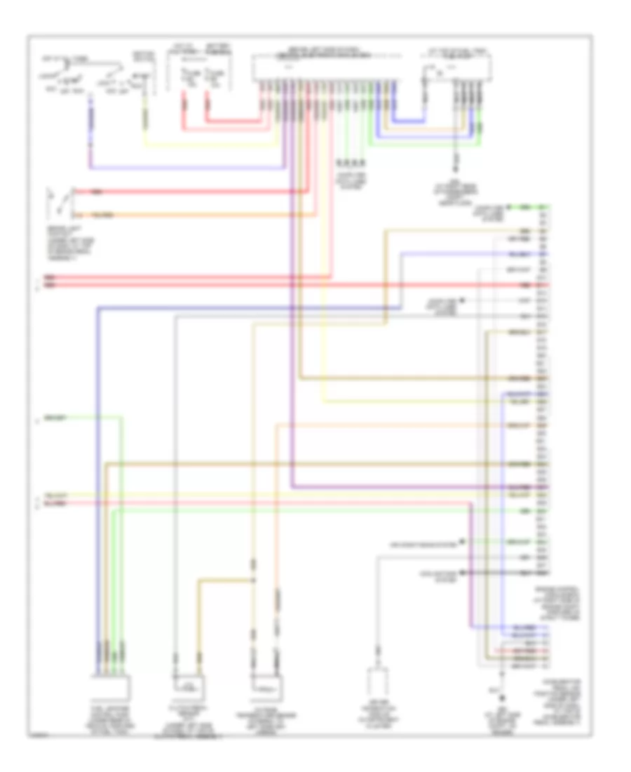
2.9L, Engine Performance Wiring Diagram (2 of 3) for Volvo S80 T-6 Premier 2005
List of elements for 2.9L, Engine Performance Wiring Diagram (2 of 3) for Volvo S80 T-6 Premier 2005:
- (at left front of engine compt) evap valve
- (at right front of engine compart) climate control system pressure sensor
- (at top front of engine, near spark plugs)
- (at top rear of engine, near spark plugs) g89
- (left front of engine compt) (turbo) intake manifold temperature sensor
- (on top rear of engine) (turbo) turbocharger control valve
- (top front of engine) (turbo) variable valve timing outlet solenoid
- C4 engine compartment relay/fuse box (at left side of engine compt forward of strut tower)
- Camshaft position sensor (on top rear of engine)
- Engine control system main relay
- Exhaust side camshaft position sensor (turbo) (at rear of engine)
- Fuse b11 20a
- Fuse b21 20a
- Fuse b23 10a
- Fuse b4 20a
- Fuse b5 15a
- Fuse b6 15a
- Fuse b8 10a
- G88
- Hot at all times
- Ignition coils
- Pnk
- Red
- Spark plug & ignition coils (top of cylinder head cover)
- Variable valve timing inlet solenoid (top front of engine)
2.9L, Engine Performance Wiring Diagram (3 of 3) for Volvo S80 T-6 Premier 2005
List of elements for 2.9L, Engine Performance Wiring Diagram (3 of 3) for Volvo S80 T-6 Premier 2005:
- (at top of fuel tank) fuel pump
- (behind left side of dash) central electronic module (cem)
- A16
- Acc
- Accelerator pedal (ap) position sensor (under left side of dash, at top of accelerator pedal assembly)
- Air conditioning system
- B10
- B11
- B12
- B13
- B14
- B15
- B16
- B17
- B18
- B19
- B20
- B21
- B22
- B23
- B24
- B25
- B26
- B27
- B28
- B29
- B30
- B31
- B32
- B33
- B34
- B35
- B36
- B37
- B38
- B39
- B40
- B41
- B42
- B43
- B44
- B45
- B46
- B47
- B48
- Battery fuse box
- Brake light contact (under left side of dash, at top of brake pedal assembly)
- C14
- C21
- C22
- C34
- C35
- Clutch pedal sensor (m/t) (under left side of dash, at top of clutch pedal assembly)
- Computer data lines system
- Cooling fans system
- D16
- D32
- D43
- D44
- D45
- D47
- D60
- Driver information module (in instrument cluster)
- Engine control module (ecm) (at right side of engine compt forward of strut tower)
- Fuel leakage control pump (under rear of vehicle, forward of fuel tank)
- Fuse e4 15a
- Fuse e5 10a
- G48 (at right rear of passenger's compt, near floor)
- G93 (at left side of engine compt, on fender)
- Hot at all times
- Ignition switch
- Lock
- Nca
- Off
- Outside temperature sensor (integral to left sideview mirror)
- Red
- Run
- Start
2.9L TURBO
2.9L Turbo, Engine Performance Wiring Diagram (1 of 3) for Volvo S80 T-6 Premier 2005
List of elements for 2.9L Turbo, Engine Performance Wiring Diagram (1 of 3) for Volvo S80 T-6 Premier 2005:
- (at rear of engine on air intake) mass airflow sensor
- (at right side of engine compt, on fender) g96
- (downstream of left catalytic converter) heated oxygen sensor 4
- (in exhaust down pipe) front heated oxygen sensor
- (on lower left rear of engine) oil pressure sensor
- (up stream of right catalytic converter) rear heated oxygen sensor
- (upstream of left catalytic converter) heated oxygen sensor 3
- A10
- A11
- A12
- A13
- A14
- A15
- A16
- A17
- A18
- A19
- A20
- A21
- A22
- A23
- A24
- A25
- A26
- A27
- A28
- A29
- A30
- A31
- A32
- A33
- A34
- A35
- A36
- A37
- A38
- A39
- A40
- A41
- A42
- A43
- A44
- A45
- A46
- A47
- A48
- A49
- A50
- A51
- A52
- A53
- A54
- A55
- A56
- A57
- A58
- A59
- A60
- A61
- A62
- A63
- A64
- A65
- A66
- A67
- A68
- A69
- A70
- Computer data lines system
- Coolant temperature sensor (left front of engine)
- Cooling fans system
- Engine control module (ecm) (at right side of engine compt, forward of strut tower)
- Engine throttle body (on top of throttle body assembly)
- Front knock sensor (at top left front of engine)
- Fuel injectors (top of engine)
- Impulse sensor (gasoline) (at rear of engine)
- Nca
- Pnk
- Rear knock sensor (at top left rear of engine)
- Red
- W/ turbo
- W/o turbo
2.9L Turbo, Engine Performance Wiring Diagram (2 of 3) for Volvo S80 T-6 Premier 2005
List of elements for 2.9L Turbo, Engine Performance Wiring Diagram (2 of 3) for Volvo S80 T-6 Premier 2005:
- (at left front of engine compt) evap valve
- (at right front of engine compart) climate control system pressure sensor
- (at top front of engine, near spark plugs)
- (at top rear of engine, near spark plugs) g89
- (left front of engine compt) (turbo) intake manifold temperature sensor
- (on top rear of engine) (turbo) turbocharger control valve
- (top front of engine) (turbo) variable valve timing outlet solenoid
- C4 engine compartment relay/fuse box (at left side of engine compt forward of strut tower)
- Camshaft position sensor (on top rear of engine)
- Engine control system main relay
- Exhaust side camshaft position sensor (turbo) (at rear of engine)
- Fuse b11 20a
- Fuse b21 20a
- Fuse b23 10a
- Fuse b4 20a
- Fuse b5 15a
- Fuse b6 15a
- Fuse b8 10a
- G88
- Hot at all times
- Ignition coils
- Pnk
- Red
- Spark plug & ignition coils (top of cylinder head cover)
- Variable valve timing inlet solenoid (top front of engine)
2.9L Turbo, Engine Performance Wiring Diagram (3 of 3) for Volvo S80 T-6 Premier 2005
List of elements for 2.9L Turbo, Engine Performance Wiring Diagram (3 of 3) for Volvo S80 T-6 Premier 2005:
- (at top of fuel tank) fuel pump
- (behind left side of dash) central electronic module (cem)
- A16
- Acc
- Accelerator pedal (ap) position sensor (under left side of dash, at top of accelerator pedal assembly)
- Air conditioning system
- B10
- B11
- B12
- B13
- B14
- B15
- B16
- B17
- B18
- B19
- B20
- B21
- B22
- B23
- B24
- B25
- B26
- B27
- B28
- B29
- B30
- B31
- B32
- B33
- B34
- B35
- B36
- B37
- B38
- B39
- B40
- B41
- B42
- B43
- B44
- B45
- B46
- B47
- B48
- Battery fuse box
- Brake light contact (under left side of dash, at top of brake pedal assembly)
- C14
- C21
- C22
- C34
- C35
- Clutch pedal sensor (m/t) (under left side of dash, at top of clutch pedal assembly)
- Computer data lines system
- Cooling fans system
- D16
- D32
- D43
- D44
- D45
- D47
- D60
- Driver information module (in instrument cluster)
- Engine control module (ecm) (at right side of engine compt forward of strut tower)
- Fuel leakage control pump (under rear of vehicle, forward of fuel tank)
- Fuse e4 15a
- Fuse e5 10a
- G48 (at right rear of passenger's compt, near floor)
- G93 (at left side of engine compt, on fender)
- Hot at all times
- Ignition switch
- Lock
- Nca
- Off
- Outside temperature sensor (integral to left sideview mirror)
- Red
- Run
- Start