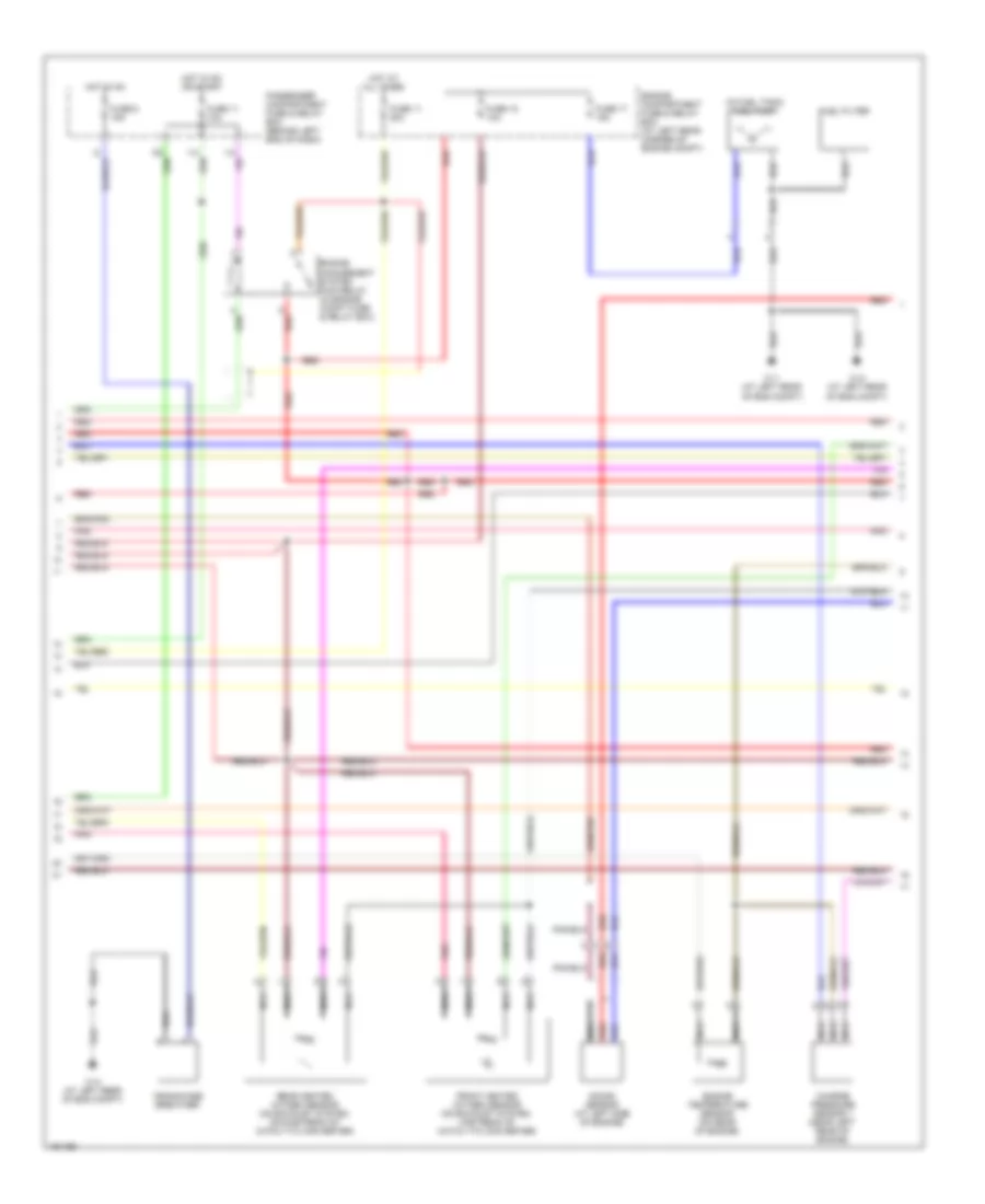
ENGINE PERFORMANCE
Engine Performance Wiring Diagram (1 of 3) for Volvo V40 LSE 2004

List of elements for Engine Performance Wiring Diagram (1 of 3) for Volvo V40 LSE 2004:
- (at left front of eng compt) evap valve
- (at right rear of eng compt, on strut tower)
- (on left side of eng compt) mass airflow (maf) sensor
- (on left side of eng compt, near air cleaner) turbocharger control valve
- + nca
- - nca
- 31/6
- 31/7 (under center of dash)
- A17
- Abs system
- B10
- B23
- Cooling fans system
- Engine management system (behind lower center of dash)
- Exhaust gas warning lamp
- Ignition coil (1 & 4 cyl)
- Ignition coil (2 & 3 cyl)
- Instrument cluster
- Leakage diagnostic pump (at left rear of vehicle)
- Micro-controller
- Nca
- Noise filter
- Pnk
- Pulse transmitter (on rear of engine)
- Red
- Tachometer
- Transmissions system
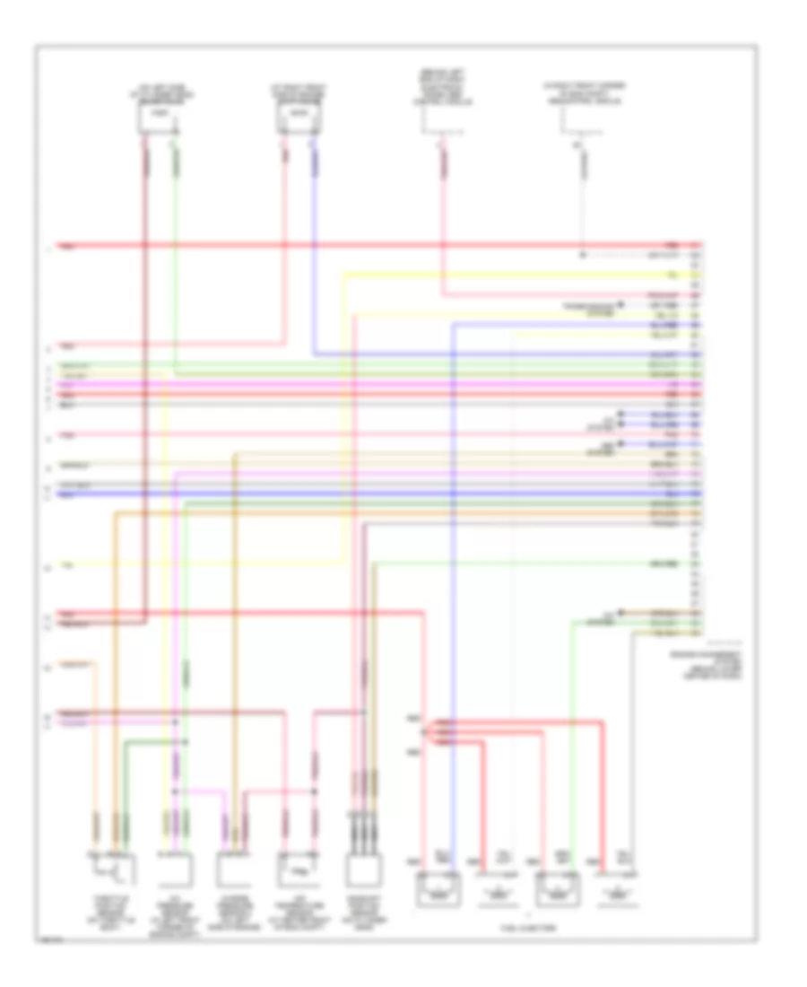
Engine Performance Wiring Diagram (2 of 3) for Volvo V40 LSE 2004
List of elements for Engine Performance Wiring Diagram (2 of 3) for Volvo V40 LSE 2004:
- (in fuel tank) fuel pump
- 31/1 (at left rear of eng compt)
- 31/2 (at left rear of eng compt)
- 31/4 (at left rear of eng compt)
- Charge pressure sensor 1 (near left rear of engine)
- Crankcase breather
- Engine compartment fuse & relay box (at left rear corner of engine compt)
- Engine management system main relay (in engine compt fuse & relay box)
- Engine temperature sensor (on rear of engine)
- Front heated oxygen sensor (on exhaust system, upstream of catalytic converter)
- Fuel filter
- Fuse 11 10a
- Fuse 11 20a
- Fuse 17 15a
- Fuse 18 10a
- Fuse 6 15a
- Hot at all times
- Hot in on
- Hot in on or start
- I13
- I14
- Knock sensor (at left side of engine)
- Nca
- Passenger compartment fuse & relay box (behind left end of dash)
- Pnk
- Rear heated oxygen sensor (on exhaust system, downstream of catalytic converter)
- Red
Engine Performance Wiring Diagram (3 of 3) for Volvo V40 LSE 2004
List of elements for Engine Performance Wiring Diagram (3 of 3) for Volvo V40 LSE 2004:
- (at right front side of engine) cvvt valve
- (behind left end of dash) electronic immobilizer control module
- (in right front corner of eng compt) abs control module
- (on left side of cylinder head) idling valve
- A/c pressure sensor (in left front corner of engine compt)
- A/c system
- Abs system
- Air temperature sensor (at center front of eng compt)
- Camshaft position sensor (on cylinder head)
- Charge pressure sensor 2 (on left side of engine)
- Engine management system (behind lower center of dash)
- Fuel injectors
- Nca
- Pnk
- Red
- Throttle position sensor (on throttle body)
- Transmissions system