ENGINE PERFORMANCE
2.4L
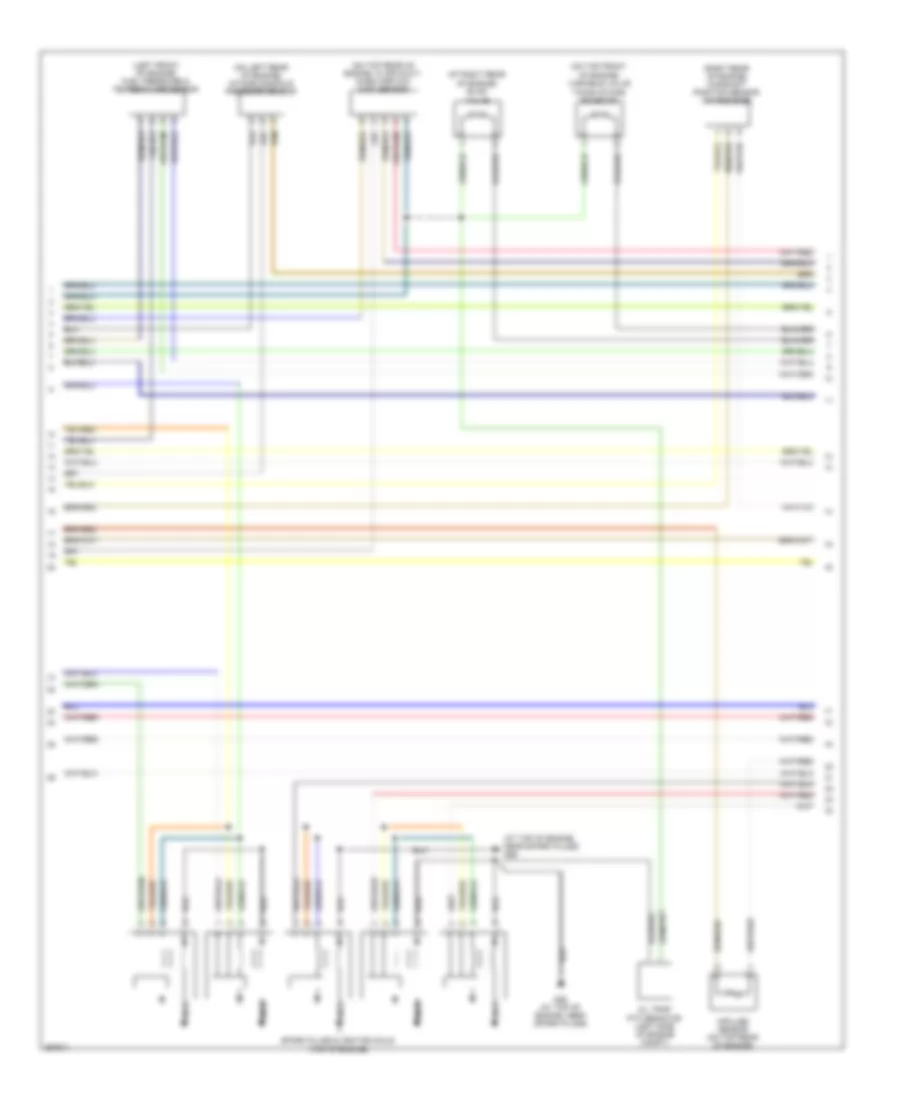
2.4L, Engine Performance Wiring Diagram (1 of 4) for Volvo V50 2007

List of elements for 2.4L, Engine Performance Wiring Diagram (1 of 4) for Volvo V50 2007:
- (at left front of engine compt) vacuum pump
- (left rear of engine compt) vacuum pump switch
- A10
- A11
- A12
- A13
- A14
- A15
- A16
- A17
- A18
- A19
- A20
- A21
- A22
- A23
- A24
- A25
- A26
- A27
- A28
- A29
- A30
- A31
- A32
- A33
- A34
- A35
- A36
- A37
- A38
- A39
- A40
- A41
- A42
- A43
- A44
- A45
- A46
- A47
- A48
- A49
- A50
- Camshaft position sensor (exhaust side) (right rear of engine)
- Center heated oxygen sensor (center of catalytic converter)
- Engine compartment distribution box (left side of engine compt)
- Engine control module (ecm) (left front of engine compt)
- Engine management system main relay
- Front heated oxygen sensor (upstream of catalytic converter)
- Front knock sensor (on left side of engine)
- Fuse f32 10a
- Fuse f33 20a
- Fuse f34 10a
- Fuse f35 15a
- Fuse f36 10a
- Fuse f9 5a
- G114 (on left front strut tower)
- Hot at all times
- Nca
- Rear heated oxygen sensor (downstream of catalytic converter)
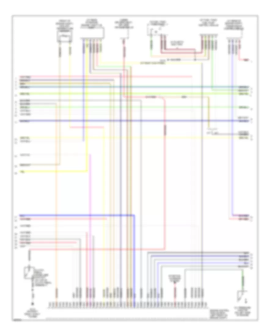
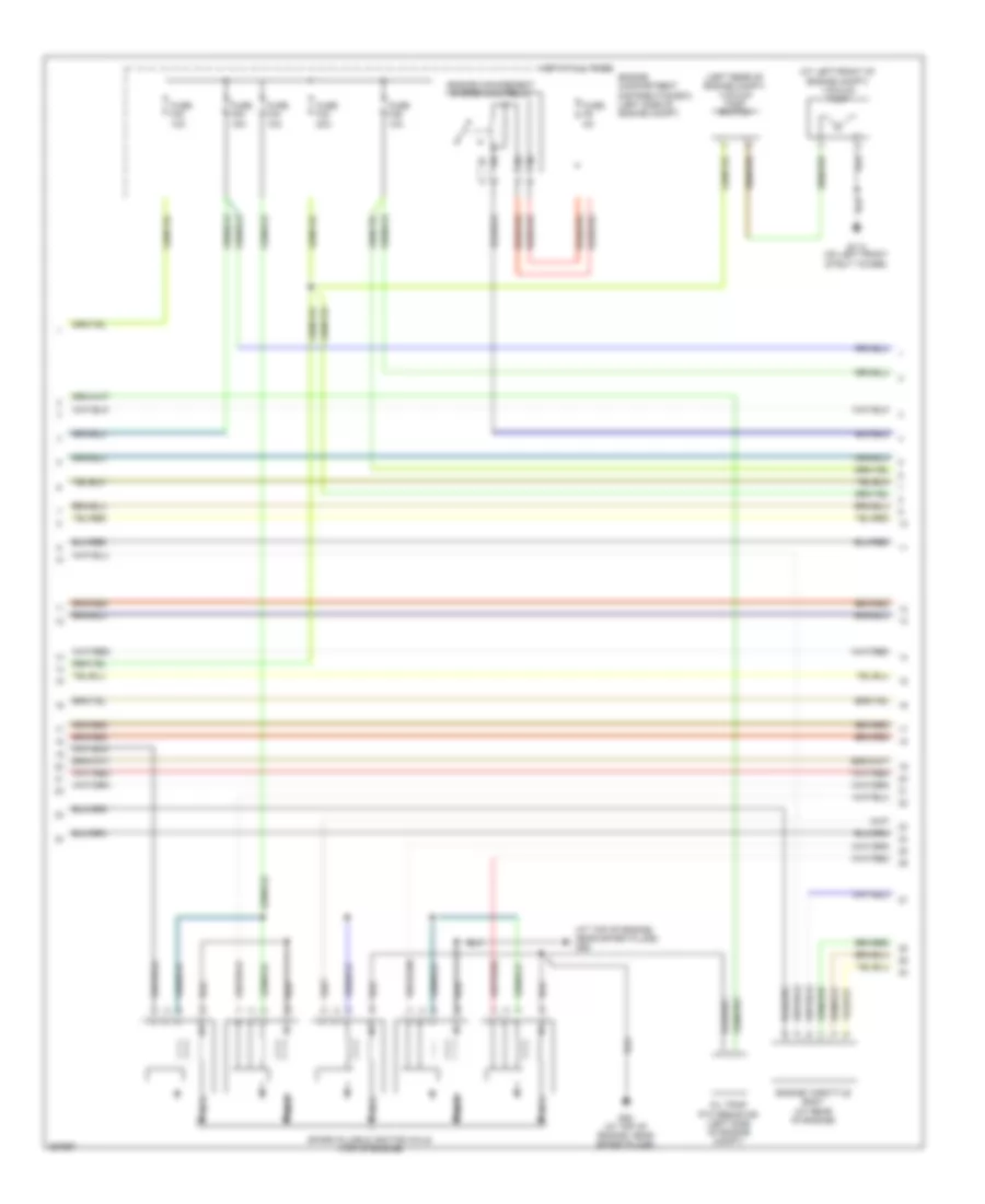
2.4L, Engine Performance Wiring Diagram (2 of 4) for Volvo V50 2007
List of elements for 2.4L, Engine Performance Wiring Diagram (2 of 4) for Volvo V50 2007:
- (at right rear of engine) evap valve
- (at top of engine, near spark plugs) g89
- (left front of engine) fuel pressure & temperature sensor
- (on left rear of engine) intake manifold pressure sensor
- (on top front of engine) variable valve timing intake solenoid
- (on top rear of engine, in air duct) mass airflow (maf) sensor
- (right rear of engine) camshaft position sensor (intake side)
- G88 (at top of engine, near spark plugs)
- Impulse sensor (on top rear of engine)
- Nca
- Oil trap ptc resistor (left side of engine compt)
- Spark plugs & ignition coils (top of engine)
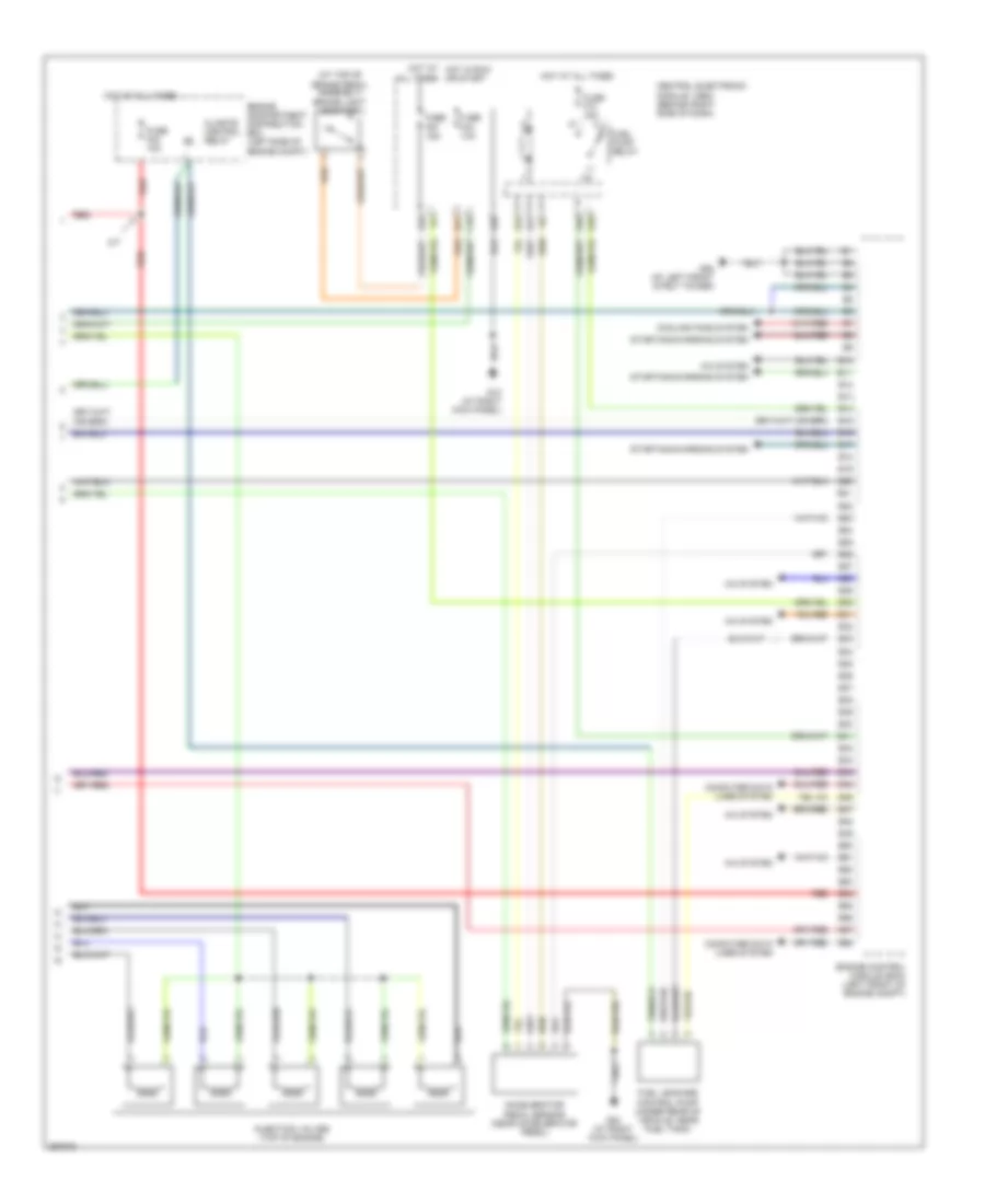
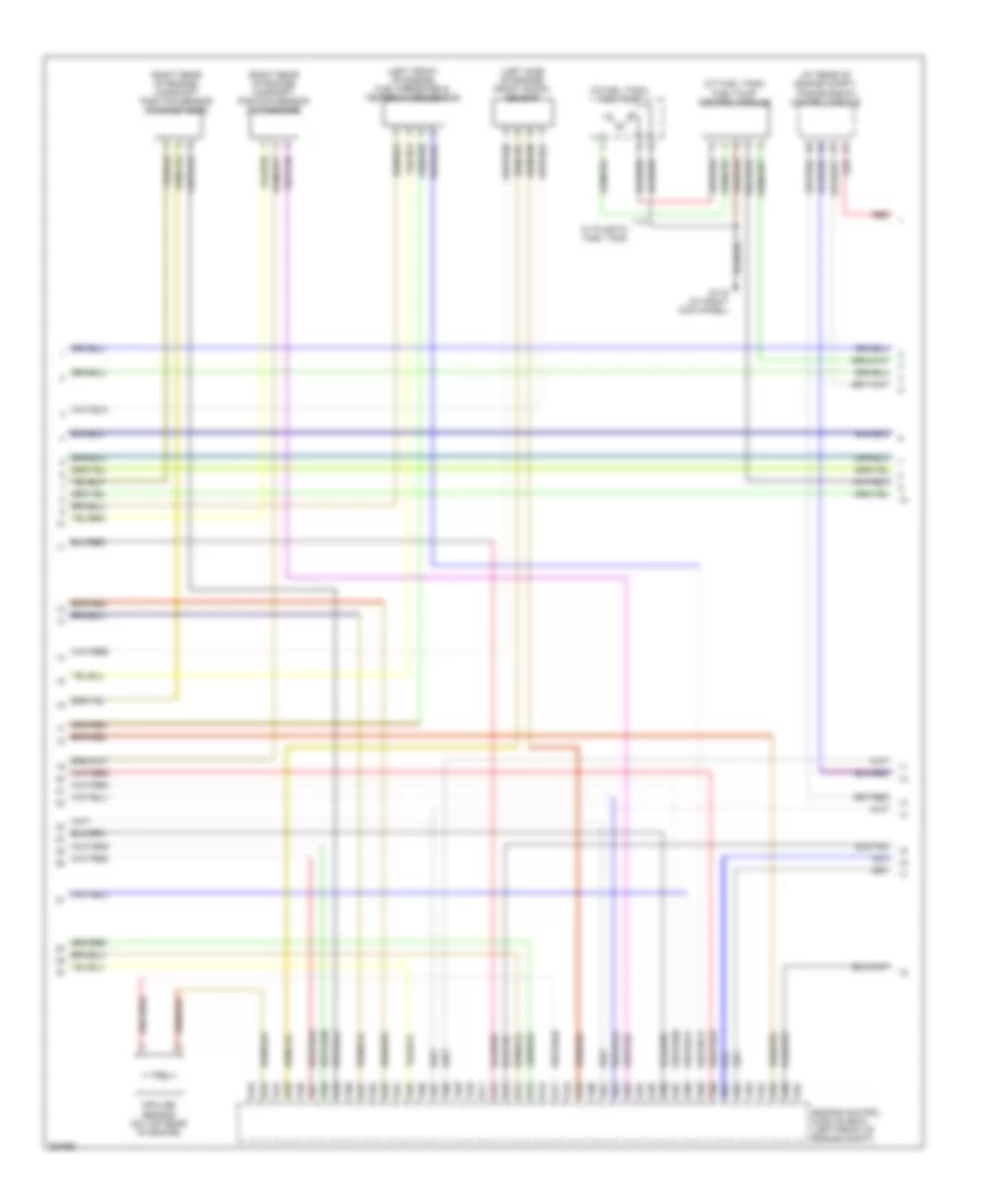
2.4L, Engine Performance Wiring Diagram (3 of 4) for Volvo V50 2007
List of elements for 2.4L, Engine Performance Wiring Diagram (3 of 4) for Volvo V50 2007:
- (at fuel tank) fuel pump control module
- (at rear of engine compt) transmission control module
- (at rear of engine) engine throttle body
- (front of engine compt) coolant temperature sensor
- (in fuel tank) fuel pump
- (under driver's seat) keyless vehicle module
- A/t
- A51
- A52
- A53
- A54
- A55
- A56
- A57
- A58
- A59
- A60
- A61
- A62
- A63
- A64
- A65
- A66
- A67
- A68
- A69
- A70
- A71
- A72
- A73
- A74
- A75
- A76
- A77
- A78
- A79
- A80
- A81
- A82
- A83
- A84
- A85
- A86
- A87
- A88
- A89
- A90
- A91
- A92
- A93
- A94
- A95
- A96
- A97
- B20
- Clutch pedal immobilizer contact (on top of clutch pedal assembly)
- Engine control module (ecm) (left front of engine compt)
- G110 (on right front strut tower)
- G116 (at right kick panel)
- M/t
- Oil pressure monitor (on left side of engine)
- Red
- Starting/ charging system
- W/ plastic gas tank
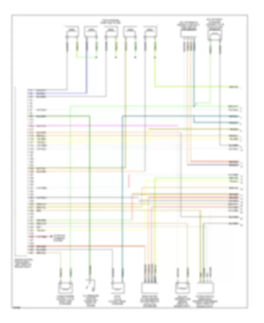
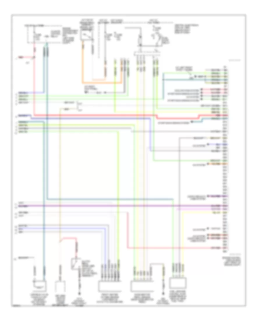
2.4L, Engine Performance Wiring Diagram (4 of 4) for Volvo V50 2007
List of elements for 2.4L, Engine Performance Wiring Diagram (4 of 4) for Volvo V50 2007:
- (at top of brake pedal assembly) brake light contact
- A/c system
- A/t
- A28
- Accelerator pedal sensor (near accelerator pedal)
- All times
- B10
- B11
- B12
- B13
- B14
- B15
- B16
- B17
- B18
- B19
- B20
- B21
- B22
- B23
- B24
- B25
- B26
- B27
- B28
- B29
- B30
- B31
- B32
- B33
- B34
- B35
- B36
- B37
- B38
- B39
- B40
- B41
- B42
- B43
- B44
- B45
- B46
- B47
- B48
- B49
- B50
- B51
- B52
- B53
- B54
- B55
- B56
- B57
- B58
- C16
- Central electronic module (cem) (behind right side of dash)
- Climate control relay
- Computer data lines system
- Cooling fans system
- E10
- E28
- E40
- E41
- Engine compartment distribution box (left side of engine compt)
- Engine control module (ecm) (left front of engine compt)
- Fuel leakage control pump (under rear of vehicle, near fuel tank)
- Fuel pump relay
- Fuse f23 10a
- Fuse f54 10a
- Fuse f57 15a
- Fuse f74 15a
- G10 (at right kick panel)
- G22
- G31
- G52 (at left front strut tower)
- G84 (at right kick panel)
- Hot at all times
- Hot at hot in run or start
- Injection valves (top of engine)
- Red
- Starting/charging system
2.5L TURBO
2.5L Turbo, Engine Performance Wiring Diagram (1 of 4) for Volvo V50 2007
List of elements for 2.5L Turbo, Engine Performance Wiring Diagram (1 of 4) for Volvo V50 2007:
- (on top front of engine) variable valve timing intake solenoid
- (on top rear of engine, in air duct) mass airflow (maf) sensor
- (top of engine) injection valves
- A10
- A11
- A12
- A13
- A14
- A15
- A16
- A17
- A18
- A19
- A20
- A21
- A22
- A23
- A24
- A25
- A26
- A27
- A28
- A29
- A30
- A31
- A32
- A33
- A34
- A35
- A36
- A37
- A38
- A39
- A40
- A41
- A42
- A43
- A44
- A45
- A46
- A47
- A48
- A49
- A50
- A51
- Coolant temperature sensor (front of engine compt)
- Engine control module (ecm) (left front of engine compt)
- Evap valve (at right rear of engine)
- Intake manifold pressure & temperature sensor (right front of engine compt)
- Nca
- Oil pressure monitor (lower left front of engine)
- Rear heated oxygen sensor (downstream of catalytic converter)
- Starting/ charging system
- Turbocharger control valve (right side of engine)
2.5L Turbo, Engine Performance Wiring Diagram (2 of 4) for Volvo V50 2007
List of elements for 2.5L Turbo, Engine Performance Wiring Diagram (2 of 4) for Volvo V50 2007:
- (at left front of engine compt) vacuum pump
- (at top of engine, near spark plugs) g89
- (left rear of engine compt) vacuum pump switch
- Engine compartment distribution box (left side of engine compt)
- Engine management system main relay
- Engine throttle body (at rear of engine)
- Fuse f32 10a
- Fuse f33 20a
- Fuse f34 10a
- Fuse f35 15a
- Fuse f36 10a
- Fuse f9 5a
- G114 (on left front strut tower)
- G88 (at top of engine, near spark plugs)
- Hot at all times
- Nca
- Oil trap ptc resistor (left side of engine compt)
- Spark plugs & ignition coils (top of engine)
2.5L Turbo, Engine Performance Wiring Diagram (3 of 4) for Volvo V50 2007
List of elements for 2.5L Turbo, Engine Performance Wiring Diagram (3 of 4) for Volvo V50 2007:
- (at fuel tank) fuel pump control module
- (at rear of engine compt) transmission control module
- (in fuel tank) fuel pump
- (left front of engine) fuel pressure & temperature sensor
- (left side of engine) front knock sensor
- (right rear of engine) camshaft position sensor (exhaust side)
- (right rear of engine) camshaft position sensor (intake side)
- A52
- A53
- A54
- A55
- A56
- A57
- A58
- A59
- A60
- A61
- A62
- A63
- A64
- A65
- A66
- A67
- A68
- A69
- A70
- A71
- A72
- A73
- A74
- A75
- A76
- A77
- A78
- A79
- A80
- A81
- A82
- A83
- A84
- A85
- A86
- A87
- A88
- A89
- A90
- A91
- A92
- A93
- A94
- A95
- A96
- A97
- Engine control module (ecm) (left front of engine compt)
- G116 (at right kick panel)
- Impulse sensor (on top rear of engine)
- Red
- W/ plastic fuel tank
2.5L Turbo, Engine Performance Wiring Diagram (4 of 4) for Volvo V50 2007
List of elements for 2.5L Turbo, Engine Performance Wiring Diagram (4 of 4) for Volvo V50 2007:
- (at left front strut tower)
- (at right kick panel) g10
- (at top of brake pedal assembly) brake light contact
- A/c system
- A/c system computer data lines system
- A/t
- A28
- Accelerator pedal sensor (near accelerator pedal)
- B10
- B11
- B12
- B13
- B14
- B15
- B16
- B17
- B18
- B19
- B20
- B21
- B22
- B23
- B24
- B25
- B26
- B27
- B28
- B29
- B30
- B31
- B32
- B33
- B34
- B35
- B36
- B37
- B38
- B39
- B40
- B41
- B42
- B43
- B44
- B45
- B46
- B47
- B48
- B49
- B50
- B51
- B52
- B53
- B54
- B55
- B56
- B57
- B58
- C16
- Central electronic module (cem) (behind right side of dash)
- Climate control relay
- Clutch pedal immobilizer contact (on top of clutch pedal assembly)
- Computer data lines system
- Cooling fans system
- E10
- E28
- E40
- E41
- Engine compartment distribution box (left side of engine compt)
- Engine control module (ecm) (left front of engine compt)
- Front heated oxygen sensor (upstream of catalytic converter)
- Fuel leakage control pump (under rear of vehicle, near fuel tank)
- Fuel pump relay
- Fuse f23 10a
- Fuse f54 10a
- Fuse f57 15a
- Fuse f74 15a
- G110 (on right front strut tower)
- G22
- G31
- G52
- G84 (at right kick panel)
- Hot at all times
- Hot in run or start
- Keyless vehicle module (under driver's seat)
- M/t
- Nca
- Red
- Starting/charging system
- Variable valve timing outlet solenoid (on top right of engine)