ENGINE PERFORMANCE
3.2L
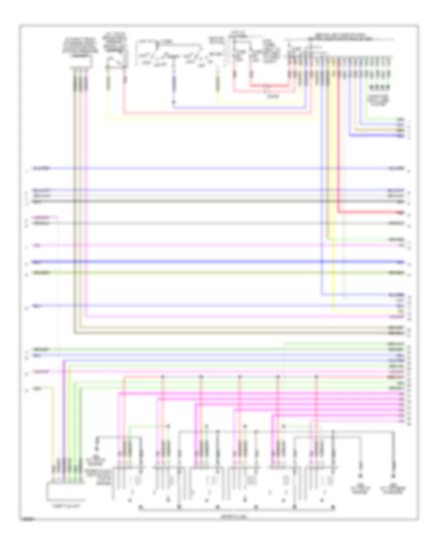
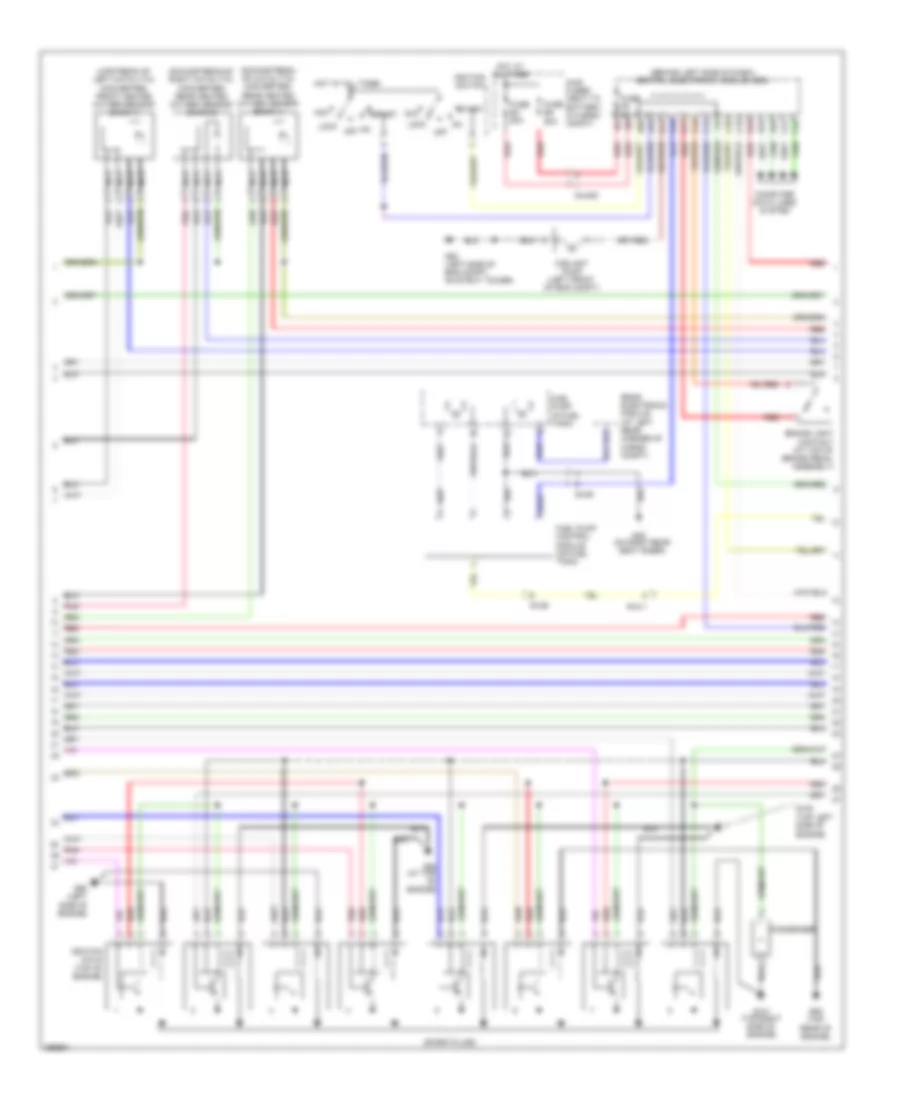
3.2L, Engine Performance Wiring Diagram (1 of 4) for Volvo XC90 2011

List of elements for 3.2L, Engine Performance Wiring Diagram (1 of 4) for Volvo XC90 2011:
- (at rear of engine) impulse sensor
- (downstream of right catalytic converter) rear heated oxygen sensor (bank 2)
- (left front of engine)
- (left side of engine compt, on strut tower) g93
- (lower left front of engine) oil level sensor
- (on intake manifold) intake manifold lower actuating motor
- (rear of engine) fuel pressure & temperature sensor
- (upstream of catalytic converter) front heated oxygen sensor (bank 2)
- 54/1b
- A10
- A11
- A12
- A13
- A14
- A15
- A16
- A17
- A18
- A19
- A20
- A21
- A22
- A23
- A24
- A25
- A26
- A27
- A28
- A29
- A30
- A31
- A32
- A33
- A34
- A35
- A36
- A37
- A38
- A39
- A40
- A41
- A42
- A43
- A44
- A45
- A46
- A47
- A48
- A49
- A50
- A51
- Coolant temperature sensor
- Engine control module (ecm) (left rear of engine compt)
- Front heated oxygen sensor (bank 1) (upstream of left catalytic converter)
- Front knock sensor (on left front side of engine)
- Intake manifold pressure sensor (left side of engine)
- Intake manifold upper actuating motor
- Intake side camshaft position sensor (on top rear of engine)
- Nca
- Outlet side camshaft position sensor (on top left rear of engine)
- Rear heated oxygen sensor (bank 1) (downstream of catalytic converter)
- Rear knock sensor (on left rear side of engine)
- Red
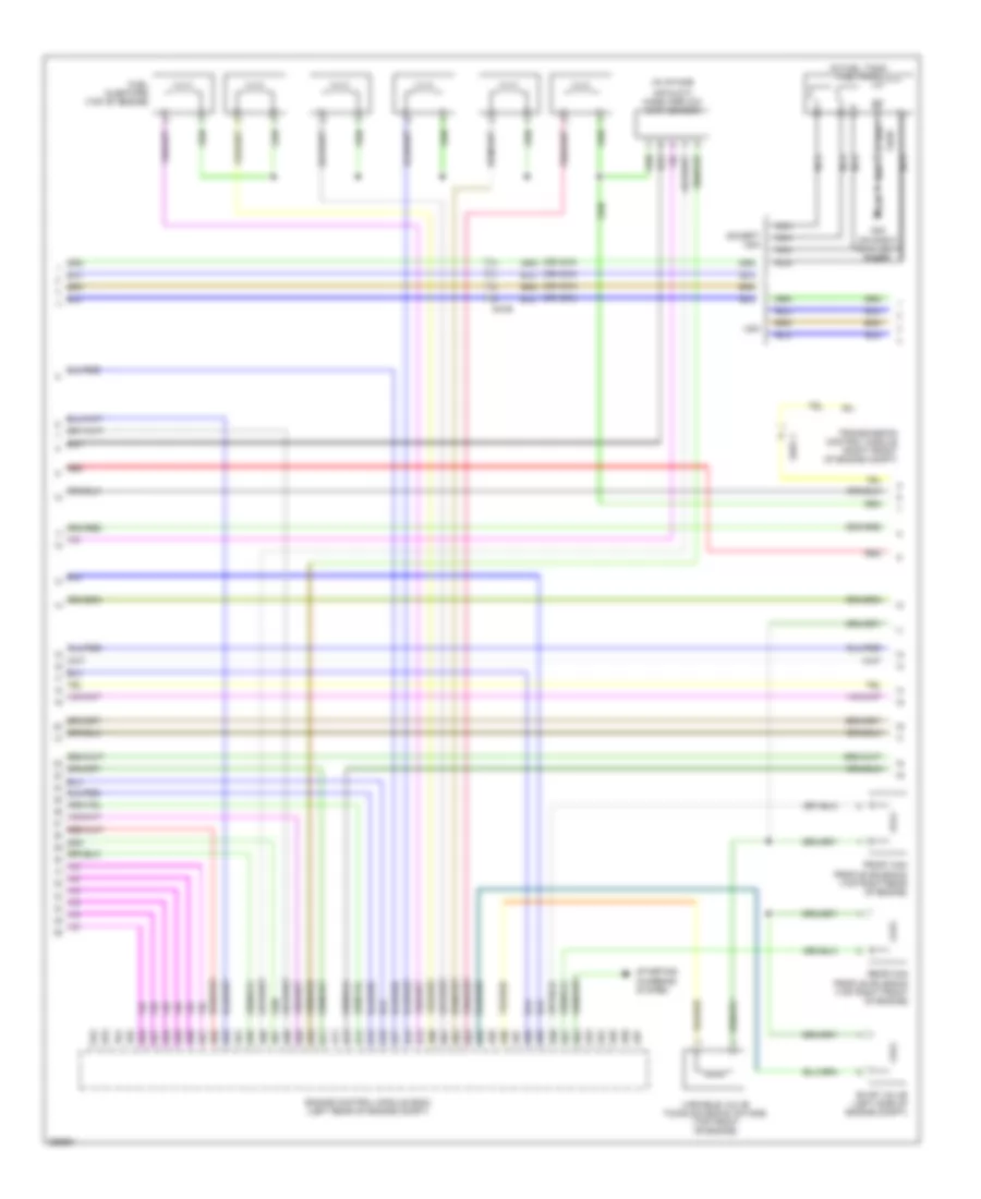
3.2L, Engine Performance Wiring Diagram (2 of 4) for Volvo XC90 2011
List of elements for 3.2L, Engine Performance Wiring Diagram (2 of 4) for Volvo XC90 2011:
- (at right front of engine compt) climate control system pressure sensor
- (at top of brake pedal assembly) brake light contact
- (behind left side of dash) central electronic module (cem)
- 54/40d
- A16
- Acc
- B11
- B16
- C14
- C15
- C21
- C22
- C34
- C35
- Computer data lines system
- D16
- D34
- D43
- D44
- D45
- D49
- D60
- Fuse e4 50a
- Fuse e5 50a
- Fuse f9 5a
- G88 (at top of engine)
- G89 (at top rear of engine)
- Hot at all times
- Ignition switch
- Lock
- Main fuses (next to battery, in cargo compt)
- Off
- Red
- Spark plug & ignition coil (top of engine)
- Spark plugs
- Start
- Throttle unit
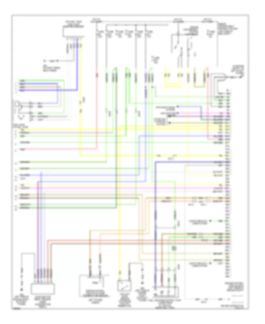
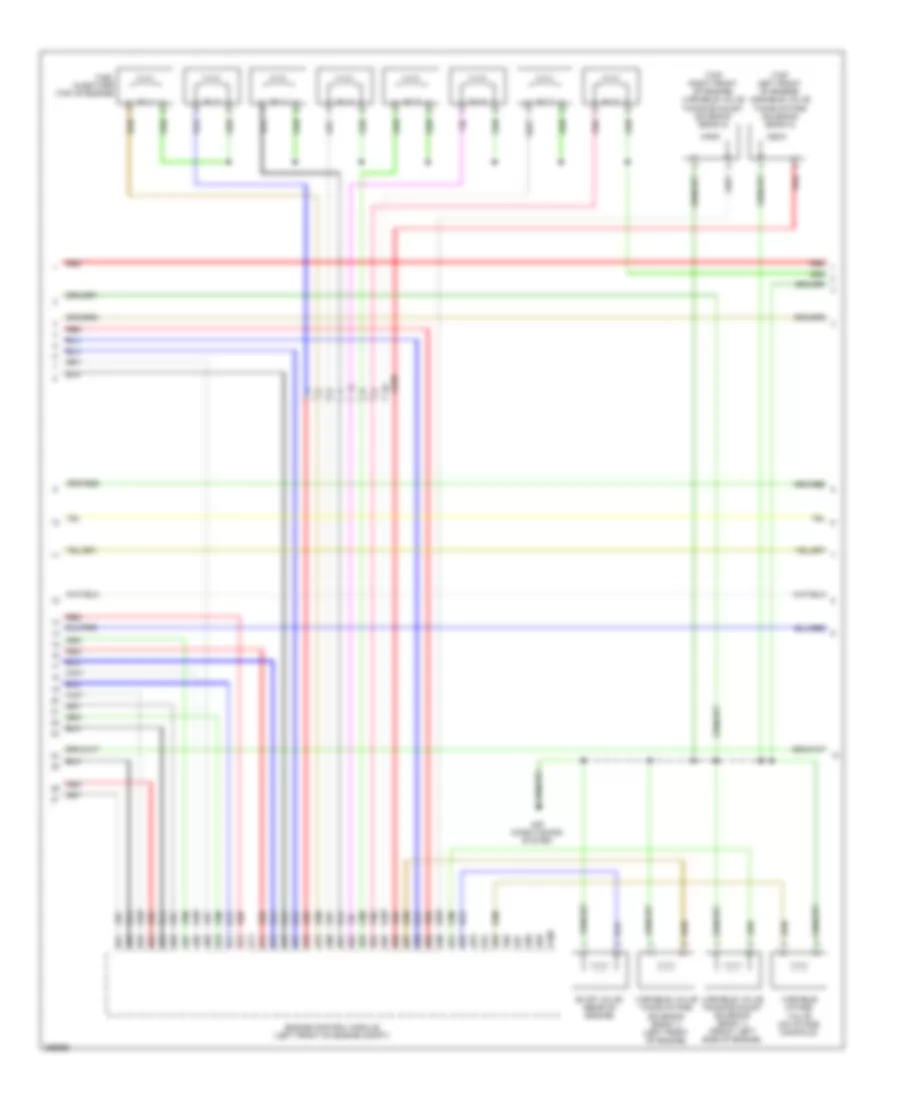
3.2L, Engine Performance Wiring Diagram (3 of 4) for Volvo XC90 2011
List of elements for 3.2L, Engine Performance Wiring Diagram (3 of 4) for Volvo XC90 2011:
- (in fuel tank) fuel pump
- (in intake
- (or nca)
- 54/36
- 54/57.1
- A52
- A53
- A54
- A55
- A56
- A57
- A58
- A59
- A60
- A61
- A62
- A63
- A64
- A65
- A66
- A67
- A68
- A69
- A70
- A71
- A72
- A73
- A74
- A75
- A76
- A77
- A78
- A79
- A80
- A81
- A82
- A83
- A84
- A85
- A86
- A87
- A88
- A89
- A90
- A91
- A92
- A93
- A94
- A95
- A96
- A97
- Air duct) mass airflow (maf) sensor
- Engine control module (ecm) (left rear of engine compt)
- Evap valve (left side of engine compt)
- Except usa
- Front cam profile solenoid (top right rear of engine)
- Fuel injectors (top of engine)
- G48 (on right rear seat riser)
- Nca
- Rear cam profile solenoid (top right front of engine)
- Red
- Starting/ charging system
- Transmission control module (right front of engine compt)
- Usa
- Variable valve timing solenoid (intake) (top front of engine)
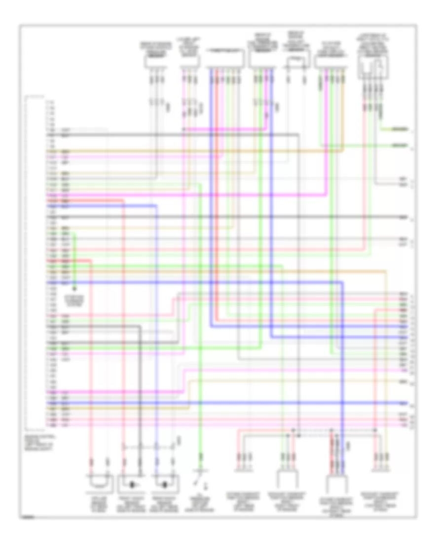
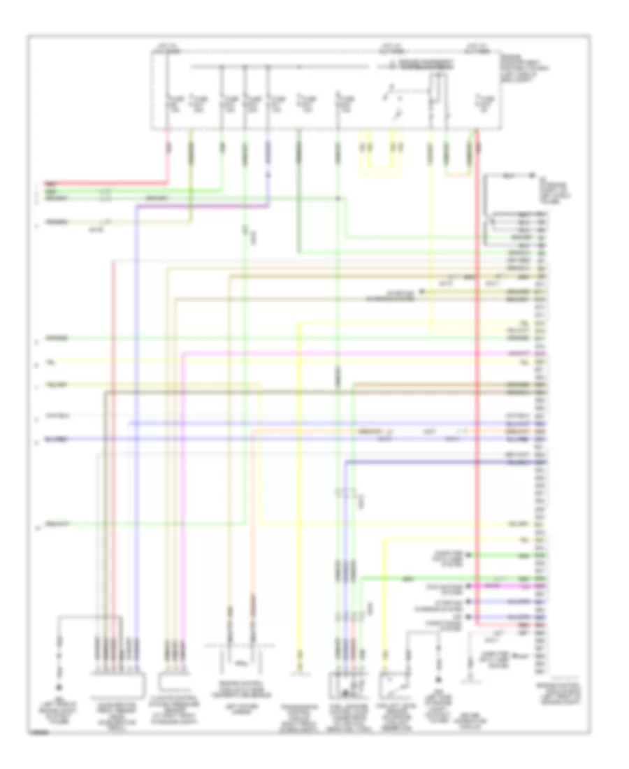
3.2L, Engine Performance Wiring Diagram (4 of 4) for Volvo XC90 2011
List of elements for 3.2L, Engine Performance Wiring Diagram (4 of 4) for Volvo XC90 2011:
- (in engine compt, on left strut tower) g2
- (on fuel tank) fuel pump control module
- 54/10
- 54/1b
- 54/3.1
- 54/3.2
- 54/34
- 54/36
- Accelerator pedal sensor (near accelerator pedal)
- Air conditioning system
- B10
- B11
- B12
- B13
- B14
- B15
- B16
- B17
- B18
- B19
- B20
- B21
- B22
- B23
- B24
- B25
- B26
- B27
- B28
- B29
- B30
- B31
- B32
- B33
- B34
- B35
- B36
- B37
- B38
- B39
- B40
- B41
- B42
- B43
- B44
- B45
- B46
- B47
- B48
- B49
- B50
- B51
- B52
- B53
- B54
- B55
- B56
- B57
- B58
- Computer data lines system
- Coolant level sensor (on engine coolant reservoir)
- Cooling fans system
- Driver information module
- Engine compartment distribution box (left side of eng compt)
- Engine control module (ecm) (left rear of engine compt)
- Engine control module outside temperature sensor
- Engine management system main relay
- Fuel leakage control pump (under rear of vehicle, near fuel tank)
- Fuel pump (in fuel tank)
- Fuse b10 20a
- Fuse b11 10a
- Fuse b12 15a
- Fuse b13 15a
- Fuse b14 20a
- Fuse b15 15a
- Fuse b19 5a
- Fuse b8 15a
- G48 (on right rear seat riser)
- G93 (left side of engine compt, on strut tower)
- Hot at all times
- Left power mirror
- Nca
- Red
- Starting/ charging system
4.4L
4.4L, Engine Performance Wiring Diagram (1 of 4) for Volvo XC90 2011
List of elements for 4.4L, Engine Performance Wiring Diagram (1 of 4) for Volvo XC90 2011:
- (in intake air duct) mass airflow (maf) sensor
- (lower left front of engine) oil level sensor
- (rear of engine)
- (rear of engine) fuel pressure & temperature sensor
- (rear of engine) intake manifold pressure sensor
- (upstream of right catalytic converter) front heated oxygen sensor (bank 2)
- 54/133
- 54/53
- 54/86
- 54/99
- A10
- A11
- A12
- A13
- A14
- A15
- A16
- A17
- A18
- A19
- A20
- A21
- A22
- A23
- A24
- A25
- A26
- A27
- A28
- A29
- A30
- A31
- A32
- A33
- A34
- A35
- A36
- A37
- A38
- A39
- A40
- A41
- A42
- A43
- A44
- A45
- A46
- A47
- A48
- A49
- A50
- A51
- A52
- A53
- A54
- A55
- A56
- A57
- A58
- A59
- A60
- Coolant temperature sensor
- Engine control module (left front of engine compt)
- Exhaust camshaft position sensor, bank 1 (right front of engine)
- Exhaust camshaft position sensor, bank 2 (top right rear of eng)
- Front knock sensor (on left front side of engine)
- Impulse sensor (at rear of eng)
- Intake camshaft position sensor, bank 1 (left rear of engine)
- Intake camshaft position sensor, bank 2 (on right rear of eng)
- Nca
- Oil pressure monitor (on left side of engine)
- Pnk
- Rear knock sensor (on left rear side of engine)
- Red
- Starting/ charging system
- Throttle unit
4.4L, Engine Performance Wiring Diagram (2 of 4) for Volvo XC90 2011
List of elements for 4.4L, Engine Performance Wiring Diagram (2 of 4) for Volvo XC90 2011:
- (behind left side of dash) central electronic module (cem)
- (downstream of catalytic converter) rear heated oxygen sensor (bank 1)
- (downstream of right catalytic converter) rear heated oxygen sensor (bank 2)
- (top left side of engine)
- (upstream of left catalytic converter) front heated oxygen sensor (bank 1)
- 54/3.1
- 54/36
- 54/40d
- A16
- Acc
- B11
- B14
- B16
- B25
- Brake light contact (at top of brake pedal assembly)
- C14
- C15
- C21
- C22
- C34
- C35
- Computer data lines system
- Condenser
- Coolant pump (left front of eng compt)
- D16
- D34
- D49
- D60
- Fuel pump (in fuel tank)
- Fuel pump control module (on fuel tank)
- Fuse e4 50a
- Fuse e5 50a
- Fuse f9 5a
- G100
- G121 (top right side of engine)
- G48 (0n right rear seat riser)
- G88 (at top of engine)
- G89 (top rear of engine)
- G90 (left side of engine)
- G93 (left side of eng compt, on strut tower)
- Hot at all times
- Ignition coils (top of engine)
- Ignition switch
- Lock
- Main fuses (next to battery, in cargo compt)
- Nca
- Off
- Pnk
- Rear electronic module (at left rear corner of cargo compt)
- Red
- Spark plugs
- Start
4.4L, Engine Performance Wiring Diagram (3 of 4) for Volvo XC90 2011
List of elements for 4.4L, Engine Performance Wiring Diagram (3 of 4) for Volvo XC90 2011:
- (top left front of engine) variable valve timing intake solenoid (bank 2)
- (top right front of engine) variable valve timing exhaust solenoid (bank 2)
- 54/99
- A100
- A61
- A62
- A63
- A64
- A65
- A66
- A67
- A68
- A69
- A70
- A71
- A72
- A73
- A74
- A75
- A76
- A77
- A78
- A79
- A80
- A81
- A82
- A83
- A84
- A85
- A86
- A87
- A88
- A89
- A90
- A91
- A92
- A93
- A94
- A95
- A96
- A97
- A98
- A99
- Air conditioning system
- Engine control module (left front of engine compt)
- Evap valve (rear of engine)
- Fuel injectors (top of engine)
- Inj 1
- Inj 2
- Inj 3
- Inj 4
- Inj 5
- Inj 6
- Inj 7
- Inj 8
- Pnk
- Red
- Variable intake valve (on intake manifold)
- Variable valve timing exhaust solenoid (bank 1) (front left side of engine)
- Variable valve timing intake solenoid (bank 1) (left front of engine)
4.4L, Engine Performance Wiring Diagram (4 of 4) for Volvo XC90 2011
List of elements for 4.4L, Engine Performance Wiring Diagram (4 of 4) for Volvo XC90 2011:
- 54/10
- 54/1b
- 54/3.1
- 54/3.2
- 54/34
- Accelerator pedal sensor (near accelerator pedal)
- Air conditioning system
- B10
- B11
- B12
- B13
- B14
- B15
- B16
- B17
- B18
- B19
- B20
- B21
- B22
- B23
- B24
- B25
- B26
- B27
- B28
- B29
- B30
- B31
- B32
- B33
- B34
- B35
- B36
- B37
- B38
- B39
- B40
- B41
- B42
- B43
- B44
- B45
- B46
- B47
- B48
- B49
- B50
- B51
- B52
- B53
- B54
- B55
- B56
- B57
- B58
- B59
- B60
- Climate control system pressure sensor (at right front of engine compt)
- Computer data lines system
- Coolant level sensor (on engine coolant reservoir)
- Cooling fans system
- Driver information module
- Engine compartment distribution box (left side of eng compt)
- Engine control module (ecm) (left front of engine compt)
- Engine control module outside temperature sensor
- Engine management system main relay
- Fuel leakage control pump (under rear of vehicle, near fuel tank)
- Fuse b10 20a
- Fuse b11 10a
- Fuse b12 15a
- Fuse b13 10a
- Fuse b14 20a
- Fuse b15 15a
- Fuse b19 5a
- Fuse b8 15a
- G2 (in engine compt, on left strut tower)
- G93 (left side of engine compt, on strut tower)
- Hot at all times
- Left power mirror
- Nca
- Red
- Starting/ charging system
- Transmission control module (right front of eng compt)