ENGINE PERFORMANCE
3.2L
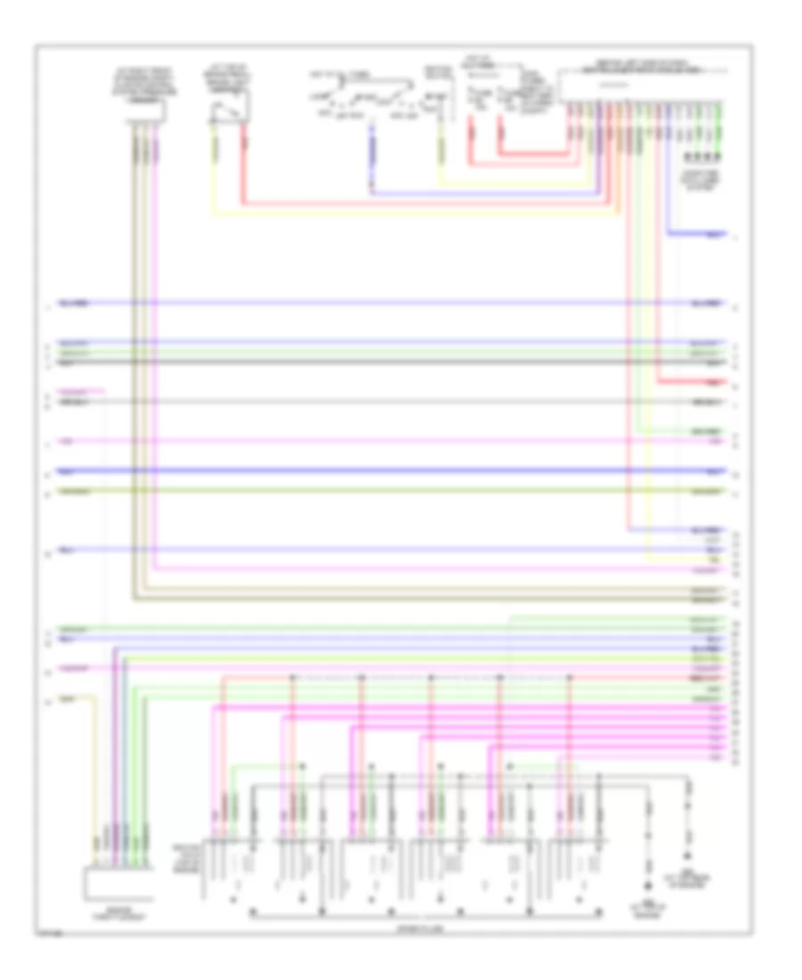
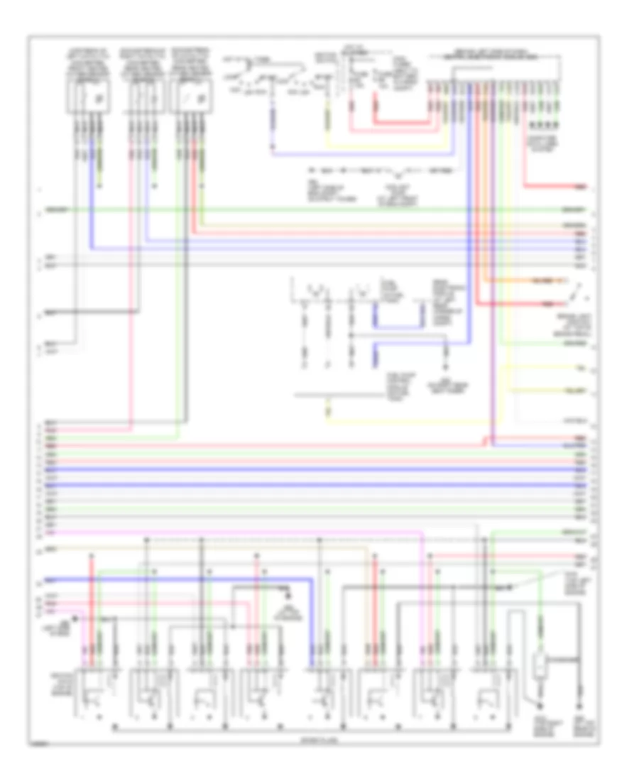
3.2L, Engine Performance Wiring Diagram (1 of 4) for Volvo XC90 R-Design 2009

List of elements for 3.2L, Engine Performance Wiring Diagram (1 of 4) for Volvo XC90 R-Design 2009:
- (at rear of engine) impulse sensor
- (downstream of right catalytic converter)
- (left front of engine)
- (lower left front of engine) oil level sensor
- (on intake manifold)
- (rear of engine) pressure & temperature sensor
- (upstream of catalytic converter) heated oxygen sensor
- A10
- A11
- A12
- A13
- A14
- A15
- A16
- A17
- A18
- A19
- A20
- A21
- A22
- A23
- A24
- A25
- A26
- A27
- A28
- A29
- A30
- A31
- A32
- A33
- A34
- A35
- A36
- A37
- A38
- A39
- A40
- A41
- A42
- A43
- A44
- A45
- A46
- A47
- A48
- A49
- A50
- A51
- Coolant temperature sensor
- Engine control module (in engine compt)
- Exhaust side camshaft position sensor (on top left rear of engine)
- Front knock sensor (on left front side of eng)
- Heated oxygen sensor (diagnostic 1)
- Heated oxygen sensor (upstream of catalytic converter)
- Intake manifold lower actuating motor
- Intake manifold pressure sensor (left side of engine)
- Intake manifold upper actuating motor
- Intake side camshaft position sensor (on top rear of engine)
- Nca
- On strut tower) g93
- Rear heated oxygen sensor (downstream of catalytic converter)
- Rear knock sensor (on left rear side of eng)
- Red
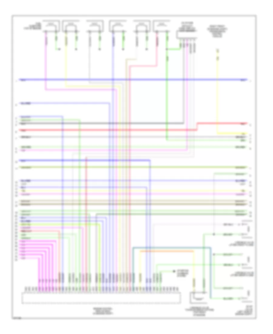
3.2L, Engine Performance Wiring Diagram (2 of 4) for Volvo XC90 R-Design 2009
List of elements for 3.2L, Engine Performance Wiring Diagram (2 of 4) for Volvo XC90 R-Design 2009:
- (at right front of engine compt) climate control system pressure sensor
- (at top of brake pedal)
- (behind left side of dash) central electronic module (cem)
- A16
- Acc
- B11
- B16
- Brake light contact
- C14
- C15
- C21
- C22
- C34
- C35
- Computer data lines system
- D16
- D34
- D49
- D60
- Engine throttle body
- Fuse e4 15a
- Fuse e5 10a
- G88 (at top of engine)
- G89 (at top rear of engine)
- Hot at all times
- Ignition coils (top of engine)
- Ignition switch
- Lock
- Main fuses (next to battery, in cargo compt)
- Off
- Red
- Run
- Spark plugs
- Start
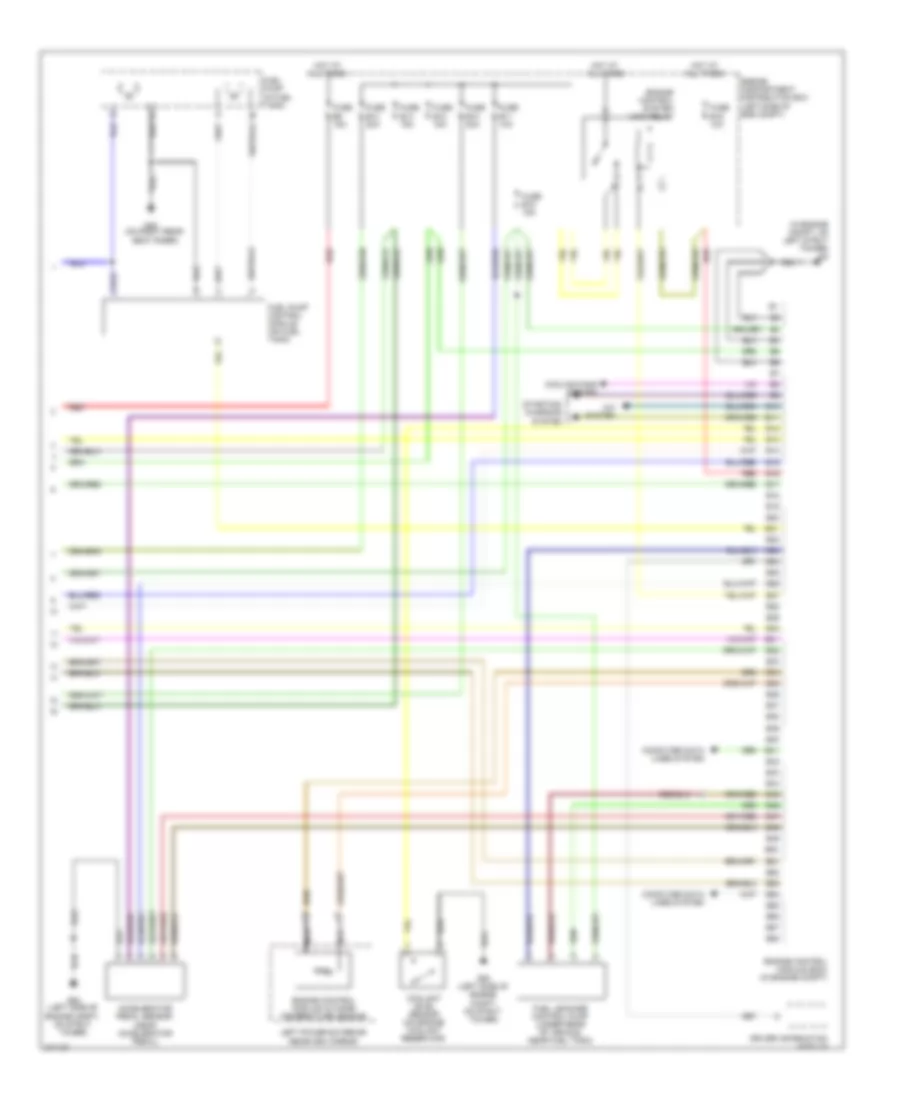
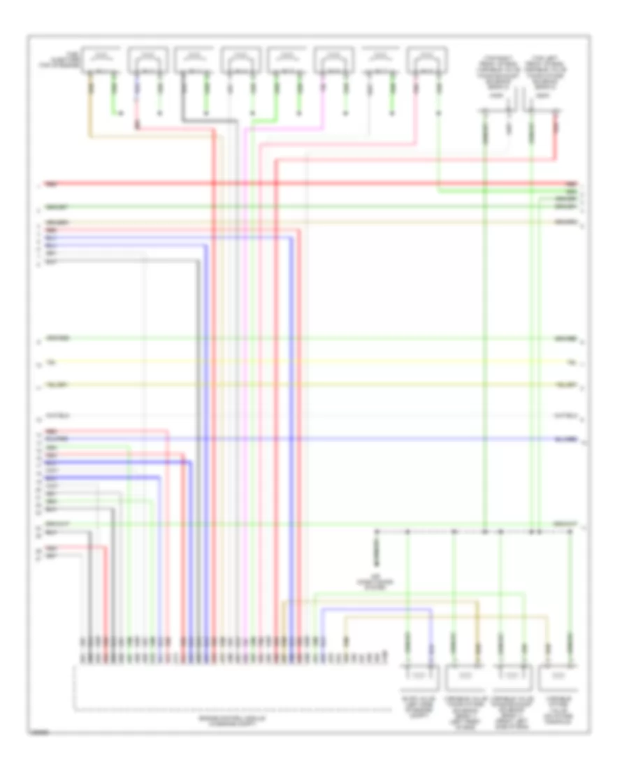
3.2L, Engine Performance Wiring Diagram (3 of 4) for Volvo XC90 R-Design 2009
List of elements for 3.2L, Engine Performance Wiring Diagram (3 of 4) for Volvo XC90 R-Design 2009:
- (in intake
- (right front of engine compt) transmission control module
- A52
- A53
- A54
- A55
- A56
- A57
- A58
- A59
- A60
- A61
- A62
- A63
- A64
- A65
- A66
- A67
- A68
- A69
- A70
- A71
- A72
- A73
- A74
- A75
- A76
- A77
- A78
- A79
- A80
- A81
- A82
- A83
- A84
- A85
- A86
- A87
- A88
- A89
- A90
- A91
- A92
- A93
- A94
- A95
- A96
- A97
- Air duct) mass airflow (maf) sensor
- Engine control module (ecm) (in engine compt)
- Evap valve (left side of engine compt)
- Fuel injectors (top of engine)
- Red
- Starting/ charging system
- Variable valve lifter (front plane)
- Variable valve lifter (rear plane)
- Variable valve timing solenoid (intake) (top front of engine)
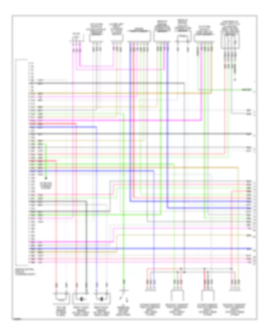
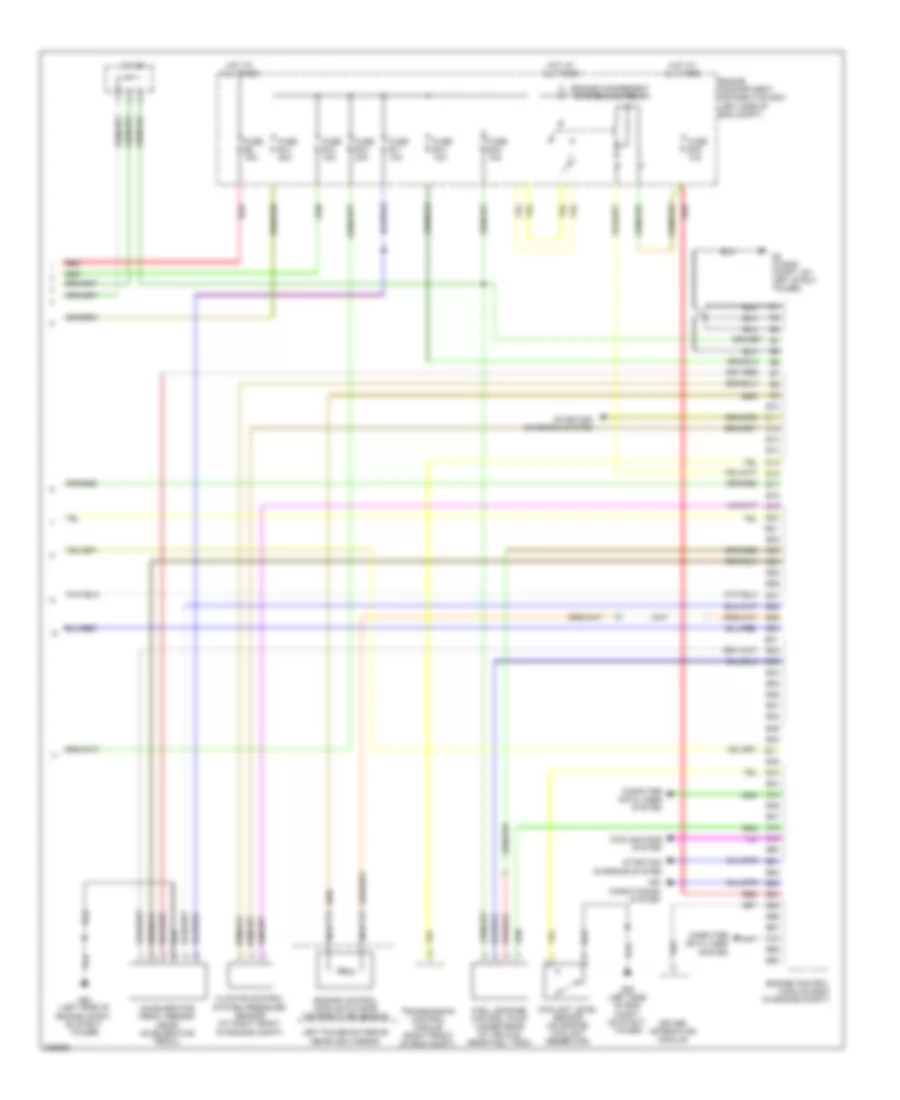
3.2L, Engine Performance Wiring Diagram (4 of 4) for Volvo XC90 R-Design 2009
List of elements for 3.2L, Engine Performance Wiring Diagram (4 of 4) for Volvo XC90 R-Design 2009:
- (in engine compt, on left strut tower) g2
- A/c system
- Accelerator pedal sensor (near accelerator pedal)
- B10
- B11
- B12
- B13
- B14
- B15
- B16
- B17
- B18
- B19
- B20
- B21
- B22
- B23
- B24
- B25
- B26
- B27
- B28
- B29
- B30
- B31
- B32
- B33
- B34
- B35
- B36
- B37
- B38
- B39
- B40
- B41
- B42
- B43
- B44
- B45
- B46
- B47
- B48
- B49
- B50
- B51
- B52
- B53
- B54
- B55
- B56
- B57
- B58
- Computer data lines system
- Coolant level sensor (on engine coolant reservoir)
- Cooling fans system
- Driver information module
- Engine compartment distribution box (left side of eng compt)
- Engine control module (ecm) (in engine compt)
- Engine control module outside temperature sensor
- Engine control system main relay
- Fuel leakage control pump (under rear of vehicle, near fuel tank)
- Fuel pump (in fuel tank)
- Fuel pump control module (on fuel tank)
- Fuse b10 20a
- Fuse b11 10a
- Fuse b12 15a
- Fuse b13 15a
- Fuse b14 20a
- Fuse b15 15a
- Fuse b19 10a
- Fuse b8 15a
- G48 (on right rear seat riser)
- G93 (left side of engine compt, on strut tower)
- Hot at all times
- Left power exterior rearview mirror
- Nca
- Red
- Starting/ charging system
4.4L
4.4L, Engine Performance Wiring Diagram (1 of 4) for Volvo XC90 R-Design 2009
List of elements for 4.4L, Engine Performance Wiring Diagram (1 of 4) for Volvo XC90 R-Design 2009:
- (in intake air duct) mass airflow (maf) sensor
- (lower left front of engine) oil level sensor
- (on intake manifold) intake manifold pressure sensor
- (rear of engine)
- (rear of engine) pressure & temperature sensor
- (upstream of right catalytic converter) front heated oxygen sensor (bank 2)
- 54/129
- A10
- A11
- A12
- A13
- A14
- A15
- A16
- A17
- A18
- A19
- A20
- A21
- A22
- A23
- A24
- A25
- A26
- A27
- A28
- A29
- A30
- A31
- A32
- A33
- A34
- A35
- A36
- A37
- A38
- A39
- A40
- A41
- A42
- A43
- A44
- A45
- A46
- A47
- A48
- A49
- A50
- A51
- A52
- A53
- A54
- A55
- A56
- A57
- A58
- A59
- A60
- Coolant temperature sensor
- Engine control module (in engine compt)
- Engine throttle body
- Exhaust camshaft position sensor, bank 1 (right front of eng)
- Exhaust camshaft position sensor, bank 2 (top right rear of eng)
- Front knock sensor (on left front side of eng)
- Impulse sensor (at rear of eng)
- Intake camshaft position sensor, bank 1 (left rear of eng)
- Intake camshaft position sensor, bank 2 (on right rear of eng)
- Nca
- Oil pressure monitor (on left side of eng)
- Pnk
- Rear knock sensor (on left rear side of eng)
- Red
- Starting/ charging system
4.4L, Engine Performance Wiring Diagram (2 of 4) for Volvo XC90 R-Design 2009
List of elements for 4.4L, Engine Performance Wiring Diagram (2 of 4) for Volvo XC90 R-Design 2009:
- (behind left side of dash) central electronic module (cem)
- (downstream of catalytic converter) rear heated oxygen sensor (bank 1)
- (downstream of right catalytic converter) rear heated oxygen sensor (bank 2)
- (top left side of engine)
- (upstream of left catalytic converter) front heated oxygen sensor (bank 1)
- A16
- Acc
- B11
- B14
- B16
- B25
- Brake light contact (at top of brake pedal)
- C14
- C15
- C21
- C22
- C34
- C35
- Computer data lines system
- Condenser
- Coolant pump (at left front of eng compt)
- D16
- D34
- D49
- D60
- Fuel pump (in fuel tank)
- Fuel pump control module (on fuel tank)
- Fuse e4 15a
- Fuse e5 10a
- G100
- G121 (top right side of engine)
- G48 (0n right rear seat riser)
- G88 (at top of engine)
- G89 (at top rear of engine)
- G90 (left side of eng)
- G93 (left side of eng compt, on strut tower)
- Hot at all times
- Ignition coils (top of engine)
- Ignition switch
- Lock
- Main fuses (next to battery, in cargo compt)
- Nca
- Off
- Pnk
- Rear electronic module (at left rear corner of cargo compt)
- Red
- Run
- Spark plugs
- Start
4.4L, Engine Performance Wiring Diagram (3 of 4) for Volvo XC90 R-Design 2009
List of elements for 4.4L, Engine Performance Wiring Diagram (3 of 4) for Volvo XC90 R-Design 2009:
- (top left front of eng) variable valve timing intake solenoid (bank 2)
- (top right front of eng) variable valve timing exhaust solenoid (bank 2)
- A100
- A61
- A62
- A63
- A64
- A65
- A66
- A67
- A68
- A69
- A70
- A71
- A72
- A73
- A74
- A75
- A76
- A77
- A78
- A79
- A80
- A81
- A82
- A83
- A84
- A85
- A86
- A87
- A88
- A89
- A90
- A91
- A92
- A93
- A94
- A95
- A96
- A97
- A98
- A99
- Air conditioning system
- Engine control module (in engine compt)
- Evap valve (left side of engine compt)
- Fuel injectors (top of engine)
- Inj 1
- Inj 2
- Inj 3
- Inj 4
- Inj 5
- Inj 6
- Inj 7
- Inj 8
- Pnk
- Red
- Variable intake valve (on intake manifold)
- Variable valve timing exhaust solenoid (bank 1) (front left side of eng)
- Variable valve timing intake solenoid (bank 1) (left front of eng)
4.4L, Engine Performance Wiring Diagram (4 of 4) for Volvo XC90 R-Design 2009
List of elements for 4.4L, Engine Performance Wiring Diagram (4 of 4) for Volvo XC90 R-Design 2009:
- 54/129
- Accelerator pedal sensor (near accelerator pedal)
- Air conditioning system
- B10
- B11
- B12
- B13
- B14
- B15
- B16
- B17
- B18
- B19
- B20
- B21
- B22
- B23
- B24
- B25
- B26
- B27
- B28
- B29
- B30
- B31
- B32
- B33
- B34
- B35
- B36
- B37
- B38
- B39
- B40
- B41
- B42
- B43
- B44
- B45
- B46
- B47
- B48
- B49
- B50
- B51
- B52
- B53
- B54
- B55
- B56
- B57
- B58
- B59
- B60
- Climate control system pressure sensor (at right front of engine compt)
- Computer data lines system
- Coolant level sensor (on engine coolant reservoir)
- Cooling fans system
- Driver information module
- Engine compartment distribution box (left side of eng compt)
- Engine control module (ecm) (in engine compt)
- Engine control module outside temperature sensor
- Engine management system main relay
- Fuel leakage control pump (under rear of vehicle, near fuel tank)
- Fuse b10 20a
- Fuse b11 10a
- Fuse b12 15a
- Fuse b13 10a
- Fuse b14 20a
- Fuse b15 15a
- Fuse b19 10a
- Fuse b8 15a
- G2 (in eng compt, on left strut tower)
- G93 (left side of eng compt, on strut tower)
- G93 (left side of engine compt, on strut tower)
- Hot at all times
- Left power exterior rearview mirror
- Nca
- Red
- Starting/ charging system
- Transmission control module (right front of eng compt)