ENGINE PERFORMANCE
6.2L VIN 8
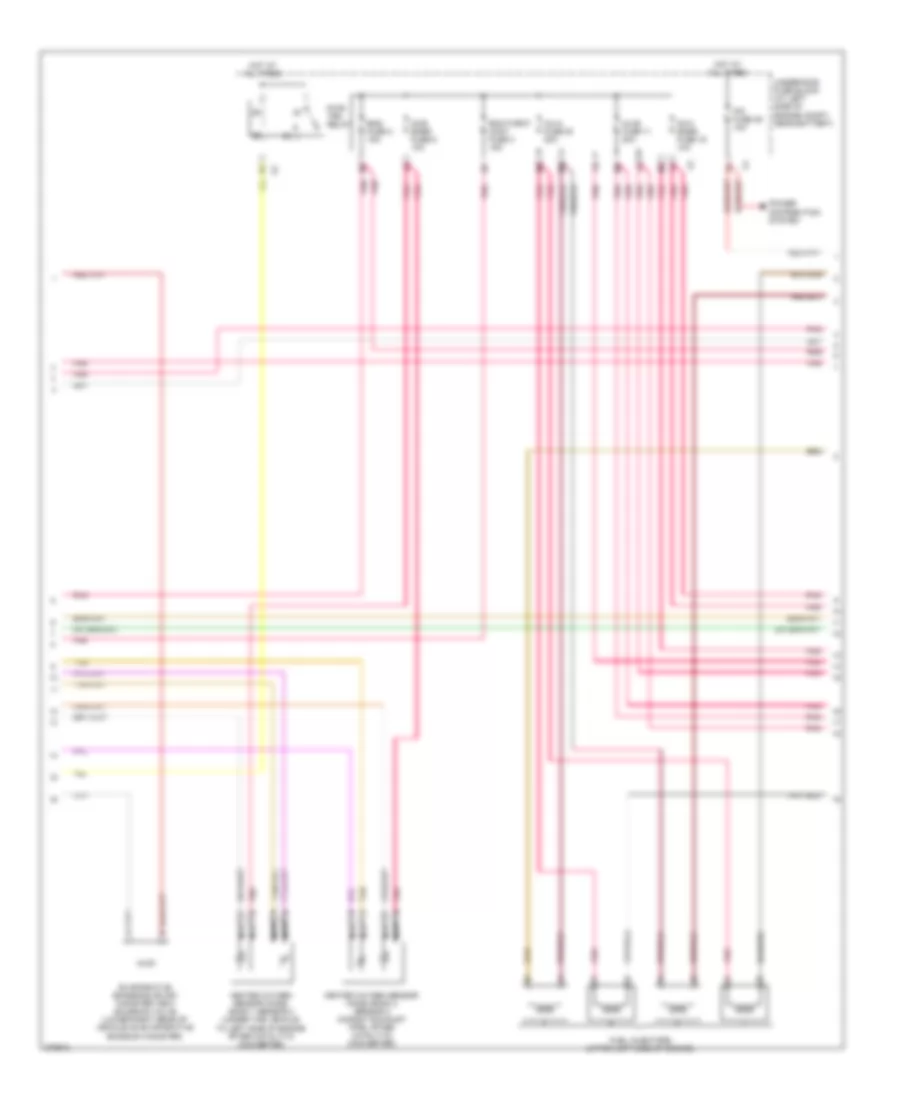
6.2L VIN 8, Engine Performance Wiring Diagram (1 of 5) for Hummer H2 2008

List of elements for 6.2L VIN 8, Engine Performance Wiring Diagram (1 of 5) for Hummer H2 2008:
- (in chassis harness 39 cm from g401 breakout) j403
- (on front of right cylinder head) g103
- 5-vol
- 5-volt ref 2
- A/c comp
- A/c pres sig
- Acc
- Acc ser data
- Accelerator pedal position (app) sensor (above accelerator pedal assembly)
- Air conditioning system
- App sens 1
- App sens 2
- Batt positive
- Body control module (bcm) (on lower left side of i/p to the left of steering column)
- Computer data lines system
- Cooling fans system
- Data bus+
- Data bus-
- Ecm batt fuse 10 10a
- Ecm ign fuse 47 15a
- Engine control module (ecm) (left front of engine compt below battery & fuse block underhood)
- Evap vent
- Exterior lights system
- Fan rel ctrl
- Ftp sig
- Fuel lvl-pri
- Fuel pump & sender assembly (in fuel tank)
- Fuel tank pressure (ftp) sensor (on fuel tank, integral to fuel pump & sender assembly)
- G103 (on front of right cylinder head)
- Ground
- Ho2s hi b1s2
- Ho2s hi b2s2
- Ho2s ht b1s2
- Ho2s ht b2s2
- Ho2s lo b1s2
- Ho2s lo b2s2
- Hot at all times
- Hot w/ run/crnk relay energized
- Iat sens sig
- Ignition switch
- Ignition vol
- J103
- J130
- J213
- J356
- Lo ref
- Lock
- Maf sens sig
- Mass air flow (maf)/intake air temperature (iat) sensor (in air induction tube)
- Mil control
- P/n sig
- Pnk
- Pnk a
- Rel ctrl
- Relay ctrl
- Rly coil ctrl
- Run
- Start
- Starting/charging system
- Tan
- Tcc brk sig
- Tcm batt fuse 12 15a
- Transmissions system
- Underhood fuse block (at left side of engine compt, near battery)
- Vehicle speed (vss) sensor (on rear of transfer case assembly above output shaft)
- Vss hi sig
- Vss lo sig
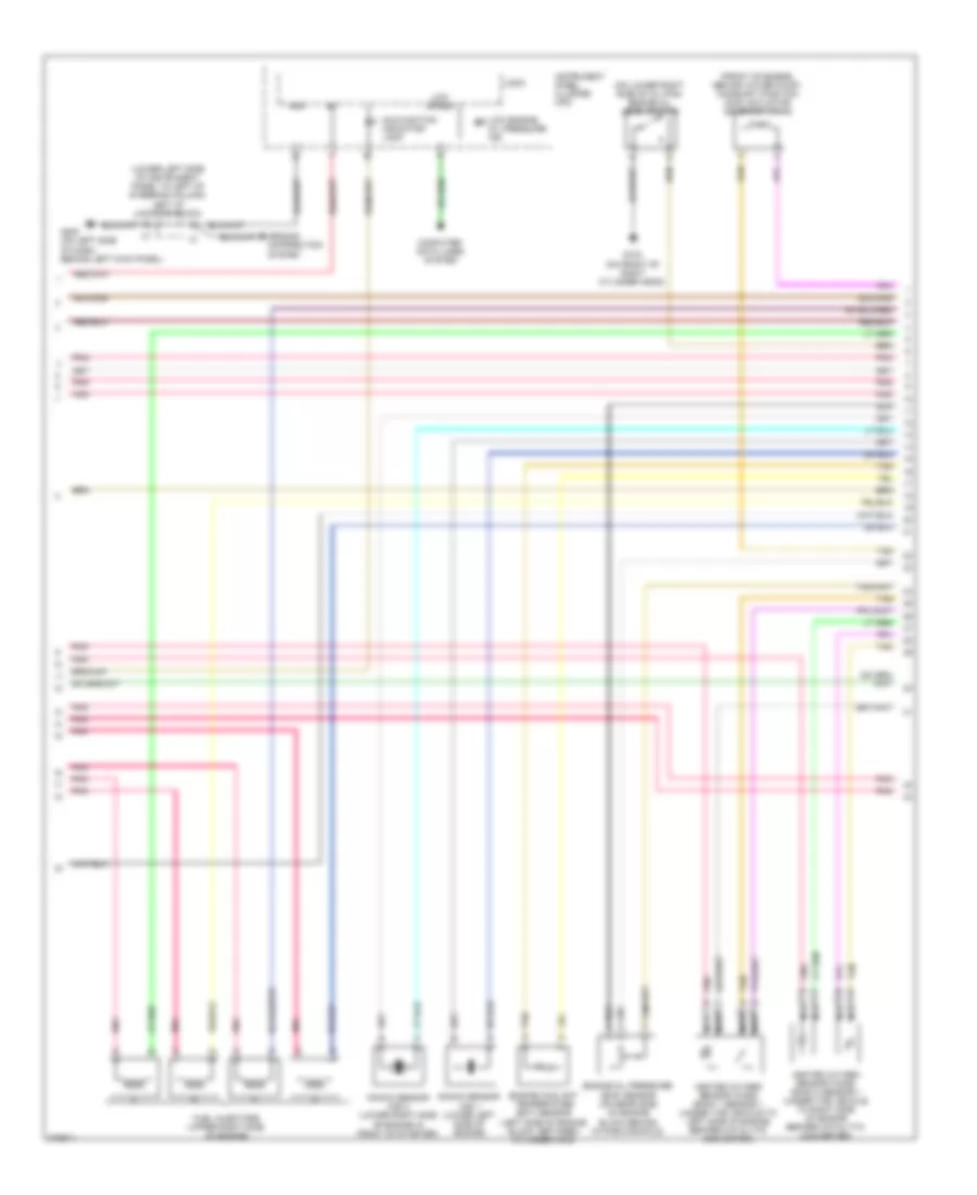
6.2L VIN 8, Engine Performance Wiring Diagram (2 of 5) for Hummer H2 2008
List of elements for 6.2L VIN 8, Engine Performance Wiring Diagram (2 of 5) for Hummer H2 2008:
- Ecm/throt cont fuse 3 15a
- Eng fuse 2 15a
- Evaporative emissions (evap) canister vent solenoid valve (lower right rear of vehicle on evaporative emission canister)
- Fuel injectors (upper left side of engine)
- Heated oxygen sensor (ho2s) bank 1 sensor 2 (under the vehicle to left side of engine after catalytic converter)
- Heated oxygen sensor (ho2s) bank 2 sensor 2 (in right exhaust pipe, after catalytic converter)
- Hot at all times
- Inj-a fuse 20 20a
- Inj-b fuse 11 20a
- Ipc fuse 39 10a
- Nca
- O2-a snsr fuse 16 10a
- O2-b snsr fuse 6 10a
- Pnk
- Power distribution system
- Pwr/ trn relay
- Tan
- Underhood fuse block (at left side of engine compt, near battery)
6.2L VIN 8, Engine Performance Wiring Diagram (3 of 5) for Hummer H2 2008
List of elements for 6.2L VIN 8, Engine Performance Wiring Diagram (3 of 5) for Hummer H2 2008:
- (front of engine, behind water pump) camshaft position (cmp) actuator solenoid valve
- (lower left side of instrument panel to left of steering column) left i/p junction block
- (on lower right side of oil pan) engine oil level switch
- Computer data lines system
- Engine coolant temperature (ect) sensor (left side of engine block, between cylinder 3 & 5)
- Engine oil pressure (eop) sensor (on rear side of engine block behind intake manifold)
- Fuel injectors (upper right side of engine)
- G103 (on front of right cylinder head)
- G200 (on left side of dash, behind left kick panel)
- Gnd
- Ground distribution system
- Heated oxygen sensor (ho2s) bank 1 sensor 1 (under the vehicle to left side of engine before catalytic converter)
- Heated oxygen sensor (ho2s) bank 2 sensor 1 (under the vehicle to right side of engine before catalytic converter)
- Instrument panel cluster (ipc)
- Knock sensor (ks) 1 (lower left side of engine)
- Knock sensor (ks) 2 (lower right side of engine in front of starter)
- Logic
- Low engine oil pressure ind
- Low speed
- Malfunction indicator lamp
- Nca
- Pnk
- Tan
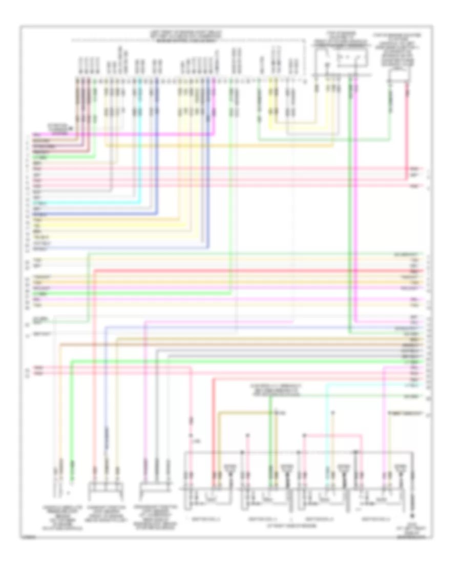
6.2L VIN 8, Engine Performance Wiring Diagram (4 of 5) for Hummer H2 2008
List of elements for 6.2L VIN 8, Engine Performance Wiring Diagram (4 of 5) for Hummer H2 2008:
- (5 cm from x111 breakout, between breakouts for ignition coils 4 & 6)
- (at right side of engine)
- (left front of engine compt below battery & fuse block underhood) engine control module (ecm)
- (top of engine mounted to intake manifold, on left side near injector 1) evaporative emission (evap) canister purge solenoid valve
- (top of engine, mounted to front of intake manifold) throttle body assembly
- 5v ref2
- A pnk
- Cam sol ctl
- Camshaft position (cmp) sensor (front of engine above crank pulley)
- Crankshaft position (ckp) sensor (at lower right rear side of engine block, behind starter solenoid)
- Ect sig
- G102 (at left front side of engine block)
- Gen fdc sig
- Ho2s ht b1s1
- Ho2s ht b2s1
- Ignition coil 2
- Ignition coil 4
- Ignition coil 6
- Ignition coil 8
- Inj 1 ctl
- Inj 2 ctl
- Inj 3 ctl
- Inj 4 ctl
- Inj 5 ctl
- Inj 6 ctl
- Inj 7 ctl
- Inj 8 ctl
- J160
- J161
- J162
- Ks1 sig
- Ks2 sig
- Lo ref
- Manifold absolute pressure (map) sensor (on top rear of engine, on intake manifold)
- Nca
- Oil lvl sw sig
- Pnk
- Red
- Sol ctrl
- Spark plug
- Starting/ charging system
- Tac mot ctl 1
- Tac mot ctl 2
- Tan
6.2L VIN 8, Engine Performance Wiring Diagram (5 of 5) for Hummer H2 2008
List of elements for 6.2L VIN 8, Engine Performance Wiring Diagram (5 of 5) for Hummer H2 2008:
- (at left side of engine)
- (mounted to left side of frame assembly) fuel pressure sensor
- (mounted to rear frame near the evap canister vent solenoid valve) fuel pump flow control module
- 5-volt
- 5v ref1
- Batt
- Chg ind sig
- Ckp sig
- Cmp sig
- Computer data lines system
- Data bus+
- Data bus-
- Drain wire
- Engine control module (ecm) (left front of engine compt below battery & fuse block underhood)
- Eop sig
- Fuel fuse 18 20a
- G102 (at left front side of engine block)
- G300 (on left side body mount, in front of driver door)
- Ground
- Ho2s hi b1s1
- Ho2s hi b2s1
- Ho2s lo b1s1
- Ho2s lo b2s1
- Hot at all times
- Ic 1 ctl
- Ic 2 ctl
- Ic 3 ctl
- Ic 4 ctl
- Ic 5 ctl
- Ic 6 ctl
- Ic 7 ctl
- Ic 8 ctl
- Ign vol
- Ignition coil 1
- Ignition coil 3
- Ignition coil 5
- Ignition coil 7
- J140
- J141
- J142 (in ignition coil jumper harness, 5 cm from x111 breakout, between the breakouts for ignition coils 3 & 5)
- J423
- Lo ref
- Lo reference
- Low ref
- Map sig
- Nca
- Pnk
- Pump ctrl
- Red
- Rel ctrl
- Sens sig
- Ser data
- Spark plug
- Starting/charging system
- Tan
- Tp sens1 sig
- Tp sens2 sig
- Underhood fuse block (at left side of engine compt, near battery)