ENGINE PERFORMANCE
4.1L
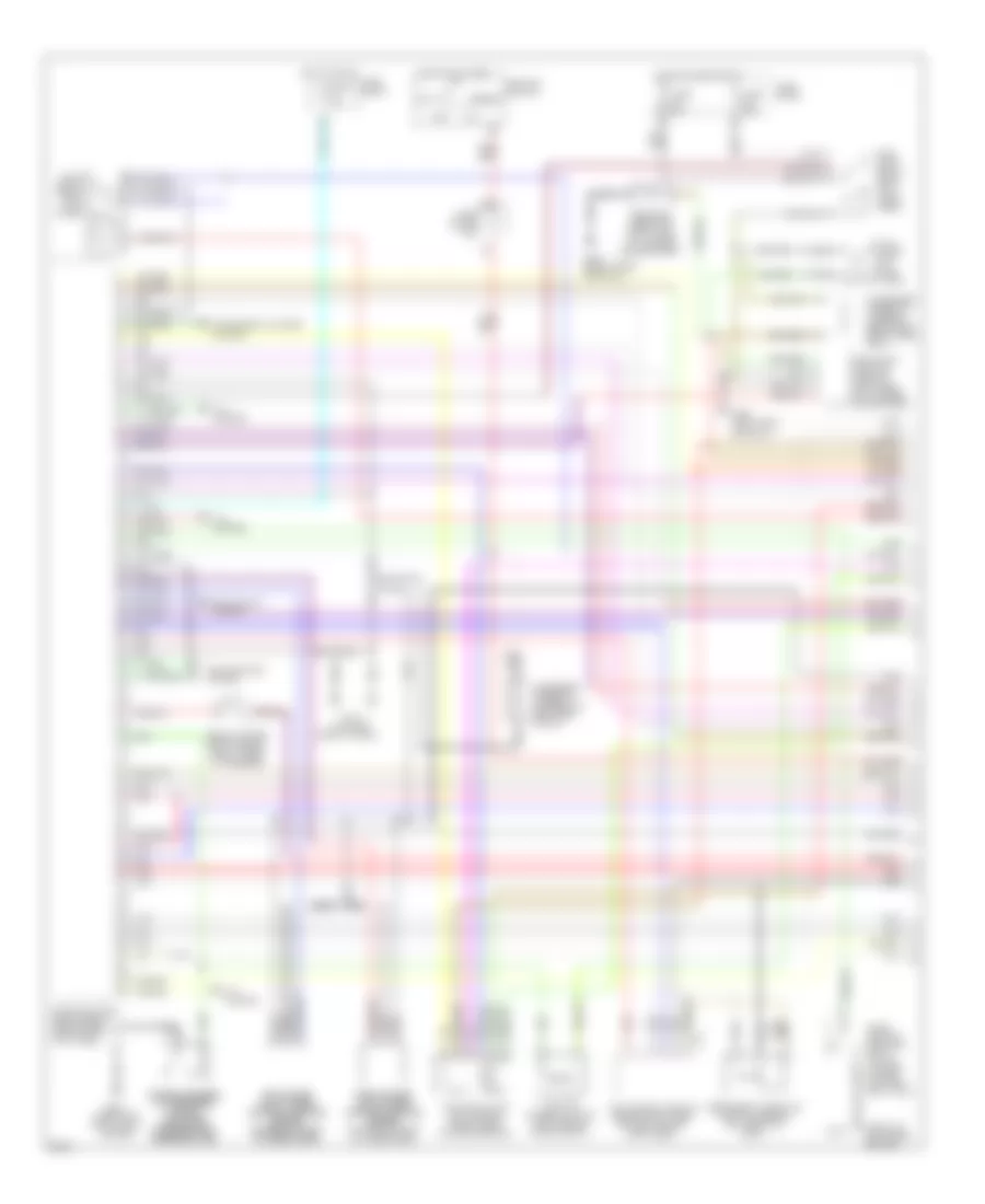
4.1L, Engine Performance Wiring Diagrams (1 of 3) for Infiniti Q45 t 1997
List of elements for 4.1L, Engine Performance Wiring Diagrams (1 of 3) for Infiniti Q45 t 1997:
- tac control module (behind right side of dash, above kick panel)
- (behind upper right side of dash, taped to harness)
- (front of left front fender)
- (front of right front fender)
- (top left
- A/c system
- Acc
- Condenser (taped to harness, above left rear wheel well)
- Condenser (taped to harness, on right side of eng)
- Cooling fans system
- Dropping resistor (right side of luggage compartment)
- Eccs relay (right kick panel)
- Engine control module (ecm) (behind right kick panel)
- F75
- Front of eng)
- Fuel pump (in fuel tank)
- Fuel pump control module (left side of luggage compatment)
- Fuel pump relay (right kick panel area)
- Fuse 15a
- Fuse 7.5a
- Fuse block
- Fuse block (j/b)
- G100
- G101
- G110
- G309 (left front door sill)
- G316 (right front door sill)
- Headlights system
- Hot at all times
- Hot in start
- Hot in start or on
- Iacv-aac valve (left side of of eng, near intake manifold)
- Iacv-ficd solenoid valve (left side of of eng compt)
- Ignition switch
- Instrument cluster system
- J/c 6
- Left intake left intake valve timing valve timing control position control position sensor sensor (in front of left (in front of left cylinder head) cylinder head)
- Nca
- Nca nca
- Off
- Park/ neutral position relay (in fuse, fusible link and relay box)
- Pnk
- Power steering power steering oil pressure oil pressure switch switch (on power (on power steering high steering high pressure line) pressure line)
- Red
- Right intake right intake valve timing valve timing control position control position sensor sensor (in front of right cylinder head)
- Secondary throttle position sensor (on throttle body)
- Start
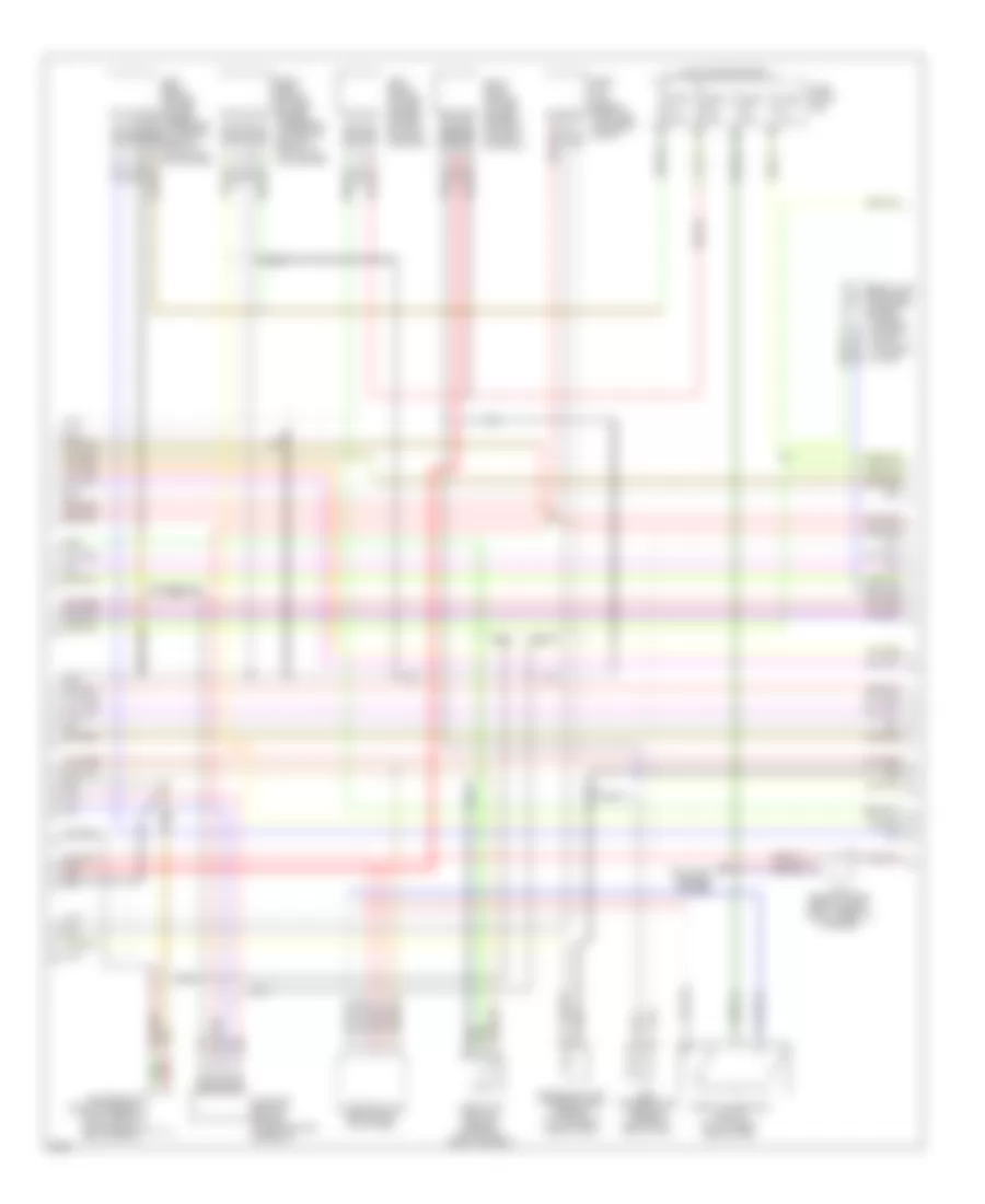
4.1L, Engine Performance Wiring Diagrams (2 of 3) for Infiniti Q45 t 1997
List of elements for 4.1L, Engine Performance Wiring Diagrams (2 of 3) for Infiniti Q45 t 1997:
- 12g
- 13h
- A/t control unit (brhind left kick panel)
- Anti-lock brakes system
- Camshaft position sensor (in distributor assembly)
- Crankshaft position sensor (right side of transmission bellhousing)
- Egr temperature sensor (in base of egr valve)
- Egr valve and evap canister purge control solenoid valve (top rear of eng)
- Engine coolant temperature sensor (on top right side of eng)
- Fuse 10a
- Fuse 7.5a
- Fuse block (j/b)
- Hot in on or start
- J/c 6 (behind upper right side of dash, taped to harness)
- Left front heated oxygen sensor (on left exhaust manifold)
- Left rear heated oxygen sensor (underside of vehicle, rear of catalytic converter)
- Mass air flow sensor (left side of engine compt)
- Nca
- Pnk
- Red
- Right front heated oxygen sensor (on right exhaust manifold)
- Right rear heated oxygen sensor (underside of vehicle, rear of catalytic converter)
- Throttle position sensor (on side of throttle body)
- Throttle position switch (on top right side of eng)
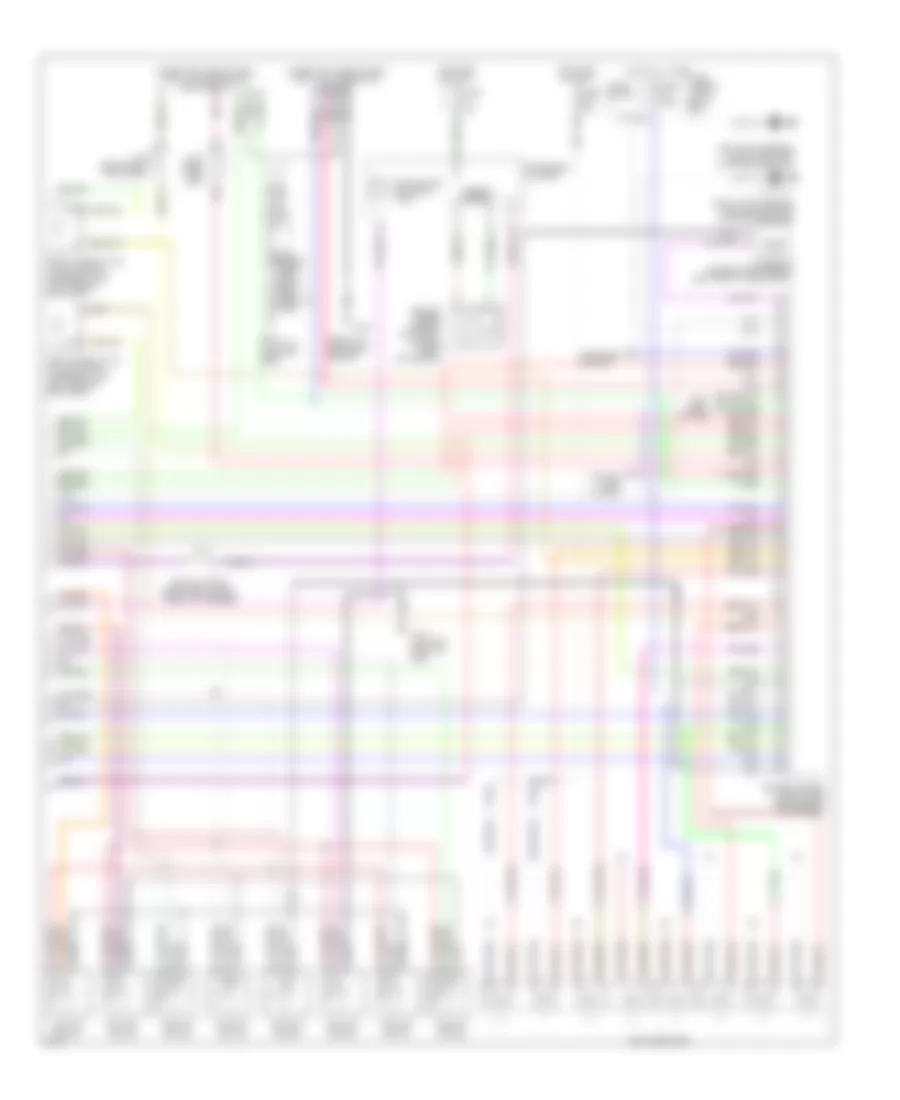
4.1L, Engine Performance Wiring Diagrams (3 of 3) for Infiniti Q45 t 1997
List of elements for 4.1L, Engine Performance Wiring Diagrams (3 of 3) for Infiniti Q45 t 1997:
- (behind upper right side of dash, taped to harness)
- (front of left front fender)
- (under left side of dash) data link connector (for consult)
- (under left side of dash) data link connector (for gst)
- Anti- theft system
- Cooling fans system
- Defogger
- Engine control module (ecm) (behind right kick panel)
- Fuel injectors
- Fuse 15a
- Fuse 7.5a
- Fuse block
- Fuse, fusible link & relay box
- G100
- G110 (top left front of eng)
- Hot at all times
- Hot in on or start
- Ignition coil #1
- Ignition coil #2
- Ignition coil #3
- Ignition coil #4
- Ignition coil #5
- Ignition coil #6
- Ignition coil #7
- Ignition coil #8
- Instrument cluster
- Intake air temperature sensor (left front of eng compt)
- J/c 2 (near fuse box)
- J/c 6
- J/c 6 (behind upper right side of dash, taped to harn)
- J/c 8 (behind left kick panel)
- Left intake valve timing control solenoid valve (left rear of eng compt)
- Left knock sensor (below left side of intake manifold)
- Malfunction indicator lamp
- Pnk
- Right intake valve timing control solenoid valve (left rear of eng compt)
- Right knock sensor (below right side of intake manifold)
- Speedo- meter
- System
- Vehicle speed sensor (on trans- mission) rear extension)

 Čeština
 Dansk
Dansk Deutsch
 Ελληνικά
 English
 English
 Suomi
Suomi Français
 Français
 עברית
עברית Hrvatski
 Magyar
 Italiano
 日本語
日本語 한국어
한국어 Nederlands
 Polski
 Português
 Português
 Română
 Русский
 Slovenčina
 Slovenščina
 Svenska
 Türkçe
 中文 (中国)