СИСТЕМА КОНДИЦИОНЕРА
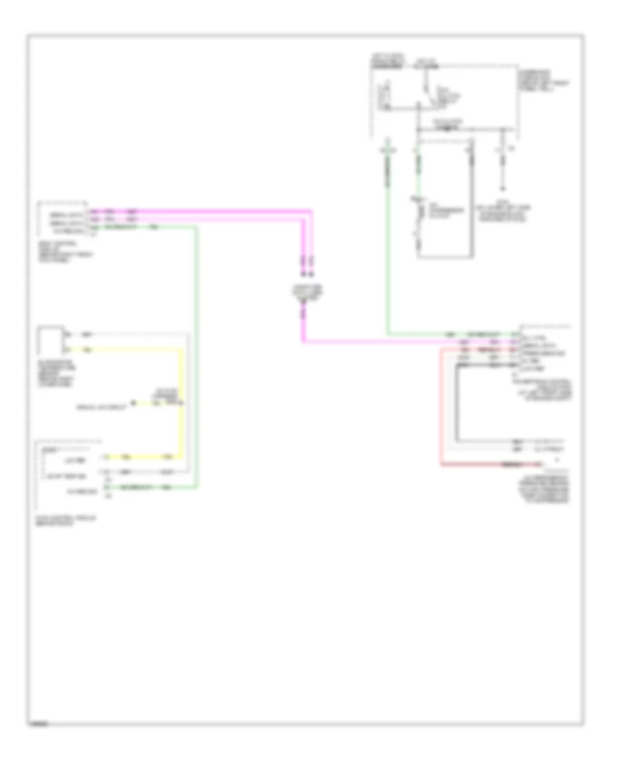
Электросхема компрессора для Hummer H3 2007
Электросхема компрессора для Hummer H3 2007 - Список элементов:
- (in hvac harness) s250
- 5v ref
- A/c clutch diode 90
- A/c clutch relay
- A/c compressor clutch
- A/c refrigerant pressure sensor (on high pressure hose connection to compressor)
- A/c req sig
- A41
- A42
- A43
- Body control module (behind right front kick panel)
- Computer data lines system
- Evap temp sig
- Evaporator temperature sensor (behind right lower dash)
- G103 (on lower left side of engine block, forward of g102)
- Hot at all times
- Hot w/ run/ crank relay energized
- Hvac control module (behind radio)
- Logic
- Low ref
- Manual a/c circuit
- Powertrain control module (pcm) (at left front side of engine compt)
- Press sens sig
- Rly ctrl
- Serial data
- Underhood fuse block (above left front wheel well)
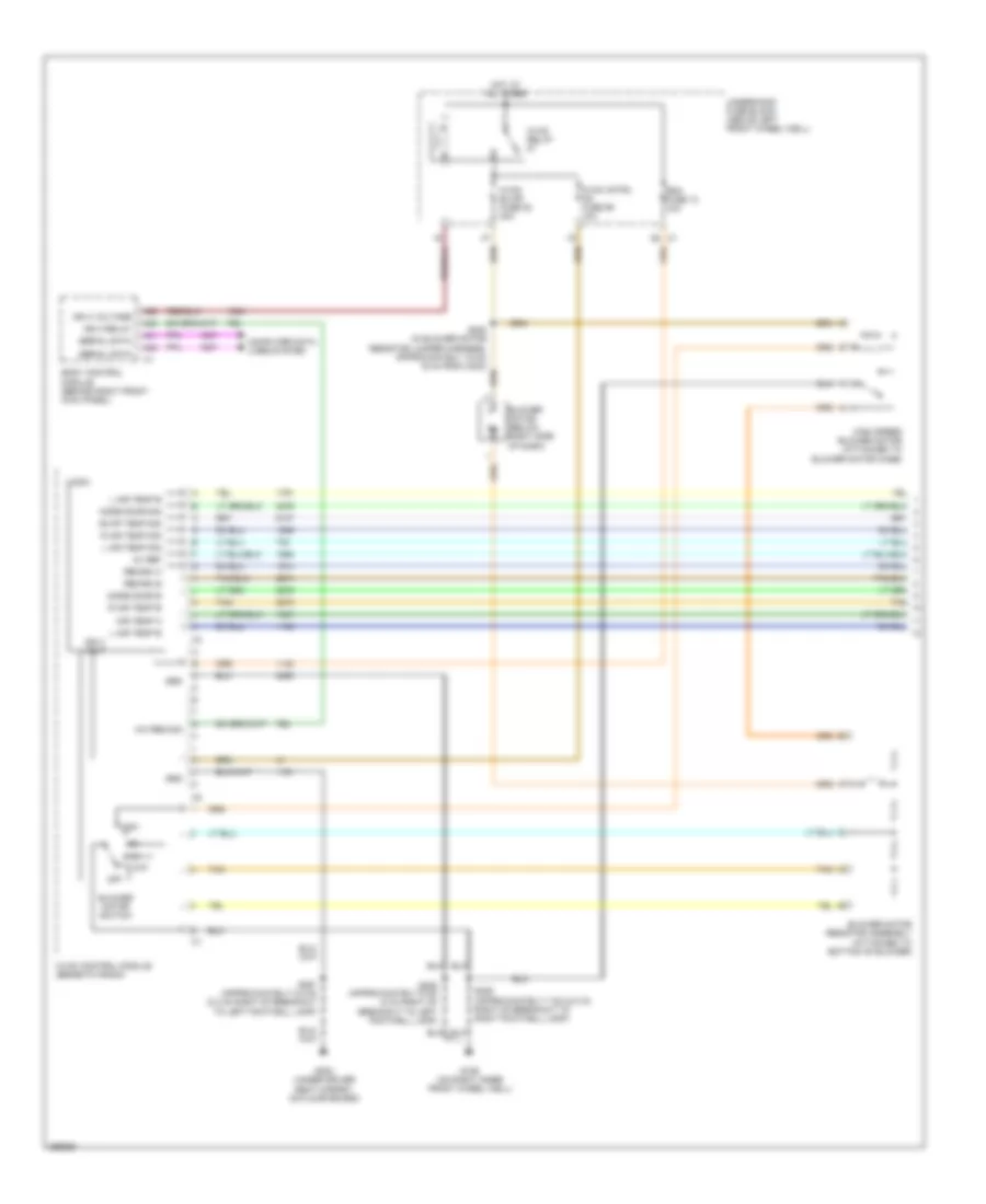
Электросхема кондиционера с ручный управлением (1 из 2) для Hummer H3 2007
Электросхема кондиционера с ручный управлением (1 из 2) для Hummer H3 2007 - Список элементов:
- 5v ref
- A/c req sig
- A26
- A41
- A42
- A43
- Air temp a
- Blower motor (below right side of dash)
- Blower motor resistor assembly (attached to bottom of blower)
- Blower motor switch
- Body control module (behind right front kick panel)
- Computer data lines system
- Evap temp sig
- G106 (on right inner front wheel well)
- G300 (under driver seat carpet, on floor board)
- Grd
- High
- High speed blower motor (attached to blower motor case)
- Hot at all times
- Hvac blwr fuse 82 30a
- Hvac cntrl hd fuse 59 10a
- Hvac control module (beneath radio)
- Hvac relay
- Ign 3 relay
- Ign 3 volt
- Ign 3 voltage
- L air temp b
- L air temp sig
- Logic
- Low
- Mode door b
- Mode door sig
- Off
- R air temp b
- R air temp sig
- Rdo fuse 13 10a
- Recirc a
- Recirc b
- S205 (approximately 5 cm (2 in) right of breakout to left footwell lamp)
- S206 (approximately 7 cm (2.8 in) right of breakout to right footwell lamp)
- S251 (approximately 0.5 cm (0.2 in) right of breakout to left footwell lamp)
- Serial data
- Tan
- Underhood fuse block (above left front wheel well)
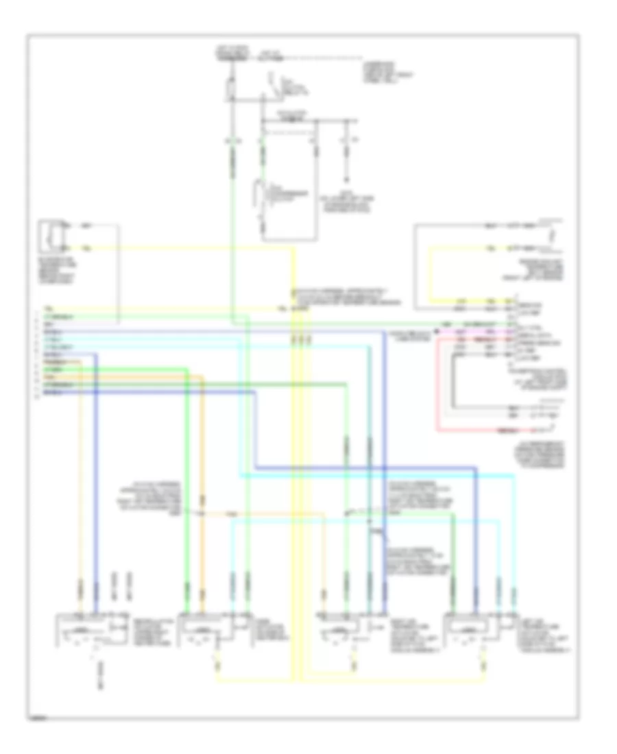
Электросхема кондиционера с ручный управлением (2 из 2) для Hummer H3 2007
Электросхема кондиционера с ручный управлением (2 из 2) для Hummer H3 2007 - Список элементов:
- (in hvac harness, approximately 10 cm (3.9 in) back from right air temperature actuator connector)
- (in hvac harness, approximately 23.5 cm (9.3 in) back from right air temperature actuator connector) s260
- (in hvac harness, approximately 28.5 cm (11.2 in) back from right air temperature actuator connector) s240
- (not used)
- 13.5 cm (5.3 in) before breakout to evaporator temperature sensor) s250
- 5v ref
- A/c clutch diode 90
- A/c clutch relay 76
- A/c compressor clutch
- A/c refrigerant pressure sensor (on high pressure hose connection to compressor)
- Computer data lines system
- Engine coolant temperature (ect) sensor (front left of engine)
- Evaporator temperature sensor (behind right lower dash)
- G103 (on lower left side of engine block, forward of g102)
- Hot at all times
- Hot w/ run/ crank relay energized
- Left air temperature actuator (mounted to left side of hvac module assembly)
- Logic
- Low ref
- Mode actuator (on side of heater box)
- Nca
- Powertrain control module (pcm) (at left front side of engine compt)
- Press sens sig
- Recirculation actuator (upper right corner of heater case)
- Right air temperature actuator (mounted to left side of hvac module assembly)
- Rly ctrl
- S230
- Sens sig
- Serial data
- Tan
- Underhood fuse block (above left front wheel well)

 Čeština
 Dansk
Dansk Deutsch
 Ελληνικά
 English
 English
 Suomi
Suomi Français
 Français
 עברית
עברית Hrvatski
 Magyar
 Italiano
 日本語
日本語 한국어
한국어 Nederlands
 Polski
 Português
 Português
 Română
 Русский
 Slovenčina
 Slovenščina
 Svenska
 Türkçe
 中文 (中国)