SHIFT INTERLOCK
Park Brake Release Wiring Diagram for Audi A4 Premium Plus 2013
 https://portal-diagnostov.com/license.html
Automotive Electricians Portal FZCO
Automotive Electricians Portal FZCO
https://portal-diagnostov.com/license.html
https://portal-diagnostov.com/license.html
Automotive Electricians Portal FZCO
Automotive Electricians Portal FZCO
List of elements for Park Brake Release Wiring Diagram for Audi A4 Premium Plus 2013:
- Abs control module (left side of engine compt)
- Auto- hold button
- Clutch position sensor (m/t)
- Computer data lines system
- Electro- mechanical parking brake control module (right side of trunk)
- Electro-mechanical parking brake button
- Fuse 30a
- Fuse 5a
- Fuse carrier
- Fuse carrier 1
- Fuse panel c (behind left end of dash)
- Fuse panel f (right side of luggage compt)
- G51 (right side of luggage compt)
- Hot at all times
- Interior lights system
- Left parking brake motor
- Right parking brake motor
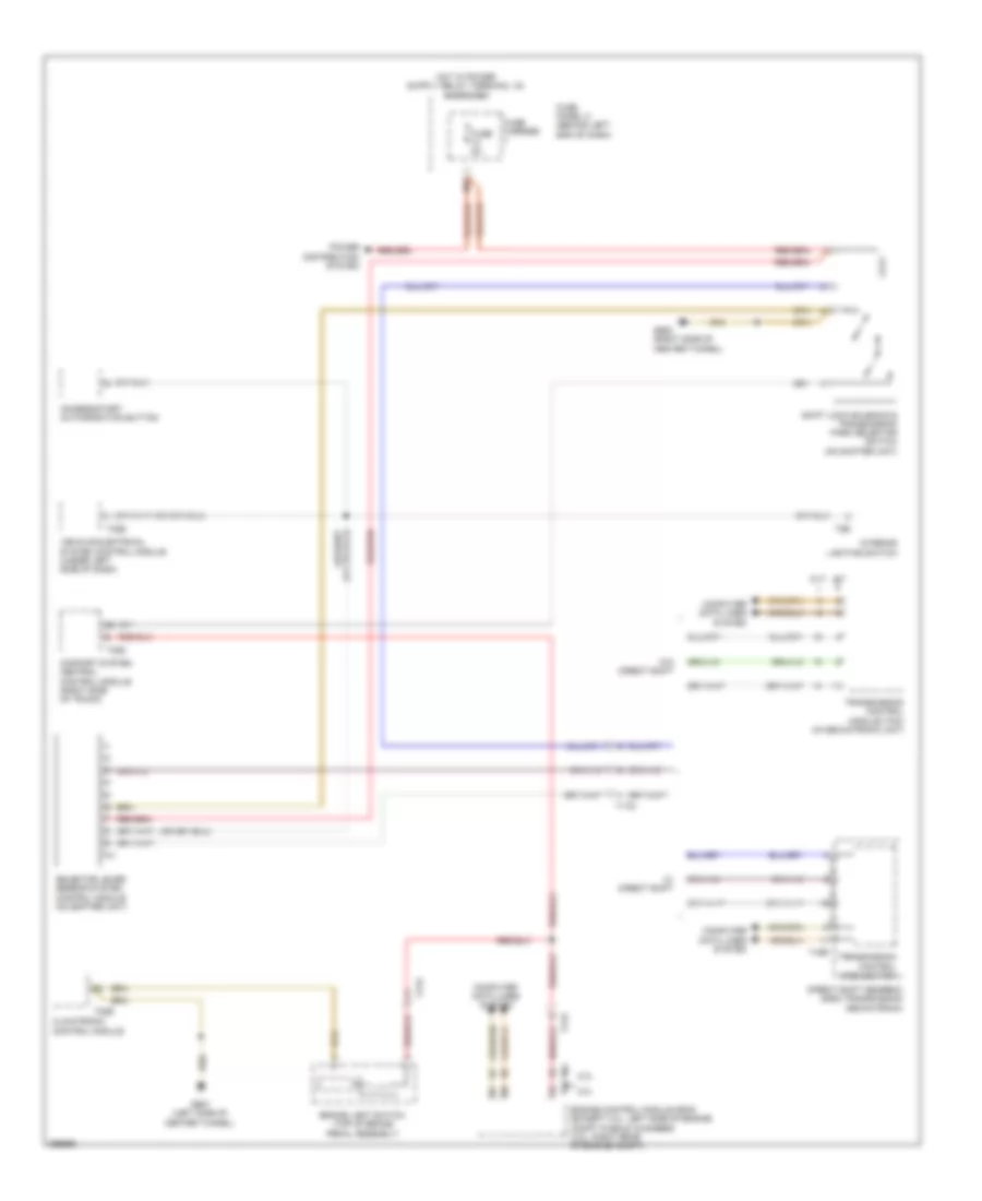
Shift Interlock Wiring Diagram for Audi A4 Premium Plus 2013
List of elements for Shift Interlock Wiring Diagram for Audi A4 Premium Plus 2013:
- 10a
- 2.0l
- 3.0l
- A/t
- Access/start authorization button
- Brake light switch (top of brake pedal assembly)
- Climatronic control module
- Comfort system central control module (right side of trunk)
- Computer data lines system
- Cvt
- Direct shift gearbox (dsg) transmission mechatronic
- Engine control module (ecm) (except 3.0l: left side of engine compt plenum chamber) (3.0l: right rear of engine compt)
- Fuse 5a
- Fuse carrier
- Fuse panel c (behind left end of dash)
- G687 (left side of center tunnel)
- G688 (right side of center tunnel)
- Interior lighting switch
- Power distribution system
- Selector lever sensor system control module (on shifter unit)
- Shift lock solenoid & transmission park selector switch (on shifter unit)
- T16r
- T17e
- T17q
- T17r
- T20e
- T32b
- T32d
- T8b
- T94
- Transmission control module (tcm)
- Transmission control module (tcm) (in mechatronic unit)
- Vehicle electrical system control module (under left side of dash)
- W/ direct shift
- W/0 direct shift
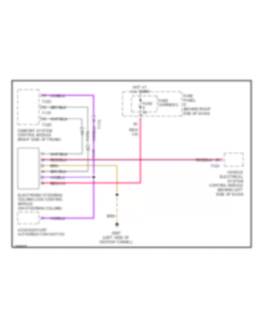
Steering Column Wiring Diagram for Audi A4 Premium Plus 2013
List of elements for Steering Column Wiring Diagram for Audi A4 Premium Plus 2013:
- Access/start authorization switch
- Comfort system control module (right side of trunk)
- Electronic steering column lock control module (on steering column)
- Fuse 5a
- Fuse carrier 2
- Fuse panel d (behind right end of dash)
- G687 (left side of center tunnel)
- Hot at all times
- T17f
- T17g
- T17p
- T32a
- T32c
- T32d
- Vehicle electrical system control module (behind left side of dash)

 Čeština
 Dansk
Dansk Deutsch
 Ελληνικά
 English
 English
 Suomi
Suomi Français
 Français
 עברית
עברית Hrvatski
 Magyar
 Italiano
 日本語
日本語 한국어
한국어 Nederlands
 Polski
 Português
 Português
 Română
 Русский
 Slovenčina
 Slovenščina
 Svenska
 Türkçe
 中文 (中国)