POWER DISTRIBUTION
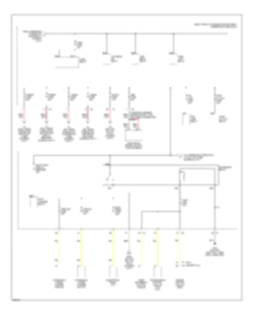
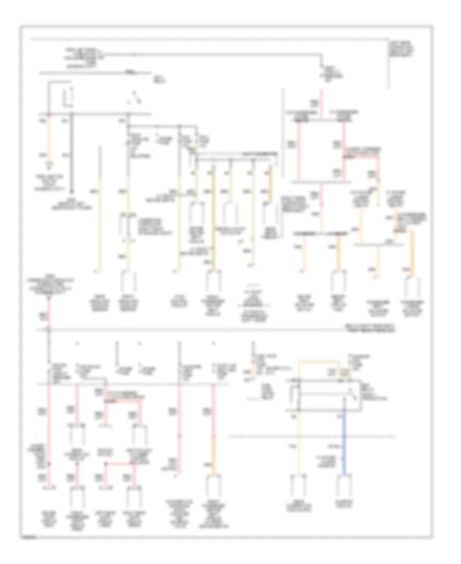
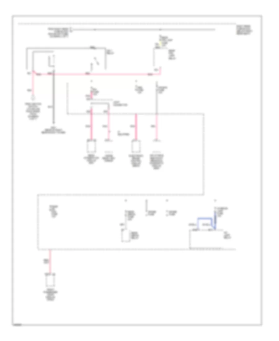
Power Distribution Wiring Diagram (1 of 7) for Cadillac CTS V 2006
 https://portal-diagnostov.com/license.html
Automotive Electricians Portal FZCO
Automotive Electricians Portal FZCO
https://portal-diagnostov.com/license.html
https://portal-diagnostov.com/license.html
Automotive Electricians Portal FZCO
Automotive Electricians Portal FZCO
List of elements for Power Distribution Wiring Diagram (1 of 7) for Cadillac CTS V 2006:
- (6.0l)
- (except 6.0l)
- (in engine harness, 15 cm from coil 1) s145
- (in engine harness, approximately 20 cm from underhood fuse block) s161
- (in fuel injector harness, 15 cm from c121) s151
- (in ignition coil/module harness, on left valve cover, 5 cm from c131) s163
- (not used)
- (right front of engine compartment) underhood fuse block
- 6.0l
- A/t
- Battery
- Blower fuse 40a
- Blower relay
- C1 g
- C2 a12
- Ccp fuse 10a
- Dash integration module (dim)
- Data link connector (dlc)
- Dim/ aldl fuse 10a
- Ecm fuse 15a
- Ecm/tcm fuse 10a
- Engine control module (ecm)
- Engine control module (ecm) (except 6.0l)
- Evaporative emissions (evap) canister purge solenoid valve
- Except 6.0l
- Flasher fuse 15a
- Fuel injector
- Fusible link
- Generator
- Heated oxygen sensor (ho2s) bank 1 sensor 2
- Heated oxygen sensor (ho2s) bank 2 sensor 2
- Hi fan fuse 30a
- Hi speed fan relay
- Hvac control module
- Ignition coil 1
- Ignition coil 3
- Ignition coil 5
- Ignition coil/ module 1
- Ignition coil/ module 3
- Ignition coil/ module 5
- Ignition coil/ module 7
- Instrument panel cluster (ipc)
- Left rear fuse block (below left rear seat)
- Low fan fuse 30a
- Low speed fan relay
- Main relay
- Odd inj/ coil fuse 20a
- Post o2 fuse 15a
- Pusher fan relay
- R14
- R19
- R20
- R39
- R40
- R47
- R48
- R49
- R50
- R51
- R52
- Reverse lock out solenoid
- S/p fan relay
- S173
- Skip shift solenoid
- Spare fuse
- Starter
- Theft deterrent control module
- To underhood fuse block (horn relay) (diagram 2 of 7)
- To underhood fuse block (pre 2/cam fuse, (diagram 3 of 7)
- Tos fuse 10a
- Trailer provisions
- Transmission control module (tcm)
- Turn signal/ hazard flasher module
- Vehicle speed sensor (vss)
- Volt check fuse 10a
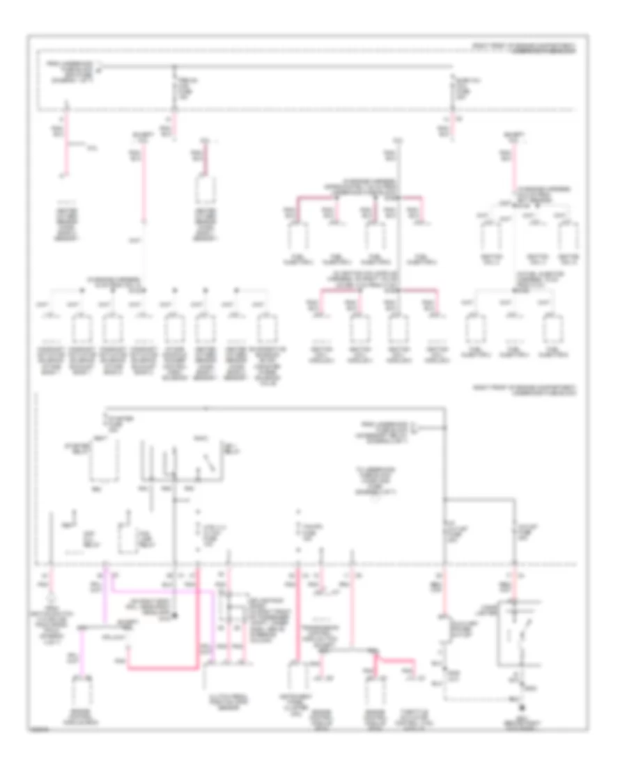
Power Distribution Wiring Diagram (2 of 7) for Cadillac CTS V 2006
List of elements for Power Distribution Wiring Diagram (2 of 7) for Cadillac CTS V 2006:
- (6.0l)
- (except 6.0l)
- (in engine harness, approximately 8 cm from ebcm connector) s130
- (right front of engine compartment) underhood fuse block
- Abs fuse 50a
- Accessory relay
- Comp clutch fuse 10a
- Comp clutch relay
- Elec prndl fuse 10a
- Electronic brake control module (ebcm)
- Electronic prndl (a/t)
- Engine control module (ecm)
- Fog lamp fuse 15a
- Fog lamp relay
- From ignition switch (pin 2) (diagram 4 of 7)
- From underhood fuse block a (main relay) (diagram 1 of 7)
- G104 (on right body rail, near right headlamp)
- Hdlp wash circuit breaker 30a
- Hdlp washer relay
- High beam relay
- Horn fuse 15a
- Horn relay
- Ign sw fuse 10a
- L rear fuse 60a
- Low beam/ hid relay
- Park lamp relay
- R rear fuse 60a
- R10
- R11
- R24
- R28
- R32
- R35
- R36
- R37
- R38
- R56
- R68
- Theft deterrent control module
- Theft fuse 7.5a
- To ignition switch (pin 6) (diagram 4 of 7)
- To left rear fuse block (driver dr mod fuse) (diagram 5 of 7)
- To left rear fuse block (pusher fan fuse) (diagram 5 of 7)
- To right rear fuse block (dr mod pwr circuit breaker) (diagram 6 of 7)
- To right rear fuse block (rim/ign sw fuse) (diagram 4 of 7)
- To underhood fuse block (i/p out let fuse) (diagram 3 of 7)
- Transmission control module (tcm) (a/t)
- Windshield wiper/ washer module
- Windshield wiper/ washer switch
- Wpr mod fuse 30a
- Wpr sw fuse 10a
Power Distribution Wiring Diagram (3 of 7) for Cadillac CTS V 2006
List of elements for Power Distribution Wiring Diagram (3 of 7) for Cadillac CTS V 2006:
- (accessory relay) (diagram 2 of 7)
- (in engine harness, 15 cm from coil 5) s142
- (in engine harness, 24.5 cm from ect sensor) s146
- (in engine harness, approximately 20 cm from underhood fuse block) s162
- (in fuel injector harness, 15 cm from c121) s152
- (in ignition coil/module harness, on right valve cover, 5 cm from c132) s164
- (on right body rail, near right headlamp) g104
- (right front of engine compartment) underhood fuse block
- 6.0l
- A/t
- Auxiliary power outlet
- Camshaft actuator solenoid exhaust bank 1
- Camshaft actuator solenoid exhaust bank 2
- Camshaft actuator solenoid intake bank 1
- Camshaft actuator solenoid intake bank 2
- Cigar lighter
- Clutch pedal position (cpp) sensor
- Cmp clu relay
- Engine control module (ecm)
- Evaporative emission (evap) canister purge solenoid valve
- Even inj/ coil fuse 20a
- Except 6.0l
- Fog lamp relay
- From ignition switch (via splice pack sp200) (pin 8) (diagram 4 of 7)
- From underhood fuse block b (ecm fuse) (diagram 1 of 7)
- From underhood fuse block h
- Fuel injector 2
- Fuel injector 4
- Fuel injector 6
- Fuel injector 8
- G201 (behind right kick panel)
- Heated oxygen sensor (ho2s) bank 1 sensor 1
- Heated oxygen sensor (ho2s) bank 2 sensor 1
- Htr vlv/ cltch fuse 10a
- I/p outlet fuse 20a
- Ign 1 relay
- Ignition coil 2
- Ignition coil 4
- Ignition coil 6
- Ignition coil/ module 2
- Ignition coil/ module 4
- Ignition coil/ module 6
- Ignition coil/ module 8
- Instrument panel cluster (ipc)
- Intake manifold runner control (imrc) solenoid
- Outlet fuse 30a
- Pnk
- Pre o2/ cam fuse 15a
- R43
- R44
- R45
- R46
- R55
- R63
- R64
- S202
- S308 (a/t)
- Splice pack sp200 (in right front of passenger compt, under dash, above steering column)
- Starter fuse 30a
- Starter relay
- Tcm/ipc fuse 15a
- Throttle actuator control (tac) module
- To underhood fuse block (wash noz fuse) (diagram 4 of 7)
- Transmission control module (tcm)
Power Distribution Wiring Diagram (4 of 7) for Cadillac CTS V 2006
List of elements for Power Distribution Wiring Diagram (4 of 7) for Cadillac CTS V 2006:
- (6.0l)
- (except 6.0l)
- (in steering column harness, 12.7 cm from c202) s207
- (not used)
- 6.0l
- A11
- Acc
- Accessory
- Cruise control switch
- Cruise control switch fuse 2a
- Dash integration module (dim)
- Engine control module (ecm)
- Except 6.0l
- From underhood fuse block (ign sw fuse) (diagram 2 of 7)
- From underhood fuse block (r rear fuse) (connector c3, pin 1) (diagram 2 of 7)
- From underhood fuse block (tcm/ipc fuse) (diagram 3 of 7)
- Ign mod/maf fuse 15a
- Ignition 1
- Ignition lock cylinder control actuator
- Ignition switch
- Inflatable restraint steering wheel module coil
- Left headlamp
- Left heated washer nozzle
- Mass air flow (maf) sensor
- Off/lock
- Pnk
- Rear integration module (rim)
- Right headlamp
- Right heated washer nozzle
- Right rear fuse block (below right rear seat)
- Right steering wheel controls (6.0l)
- Rim/ ign sw fuse 10a
- Run
- S206 (in steering column harness, 12.7 cm from c202)
- Spare fuse
- Splice pack sp200 (in right front of passenger compt, under dash, above steering column)
- Start
- Steering column fuse block (taped to steering column harness)
- Strg ctls fuse 10a
- To left rear fuse block (ign 3 relay) (diagram 6 of 7)
- To right rear fuse block (ign 1 relay) (diagram 7 of 7)
- To underhood fuse block (accessory relay) (connector c4, pin 37) (diagram 2 of 7)
- To underhood fuse block (cmp clu relay) (diagram 3 of 7)
- Turn signal switch
- Turn signal/ multifunction switch
- Underhood fuse block (right front of engine compartment)
- W/ automatic headlamps control leveling system
- W/ windshield heated washer nozzels
- Wash noz fuse 10a
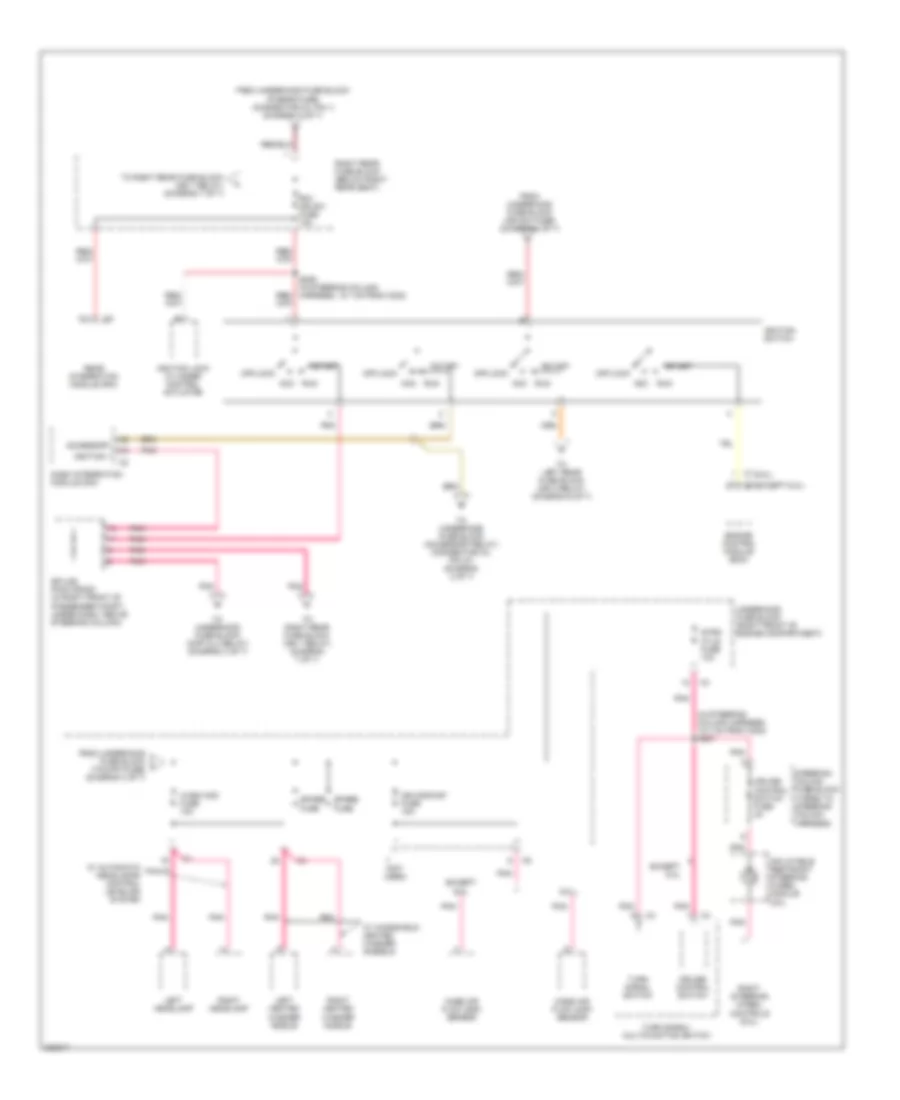
Power Distribution Wiring Diagram (5 of 7) for Cadillac CTS V 2006
List of elements for Power Distribution Wiring Diagram (5 of 7) for Cadillac CTS V 2006:
- (below left rear seat) left rear fuse block
- (in driver seat harness, 8 cm from msm connector) s351
- (in headliner harness, 22.5 cm from radio antenna module) s313
- A12
- Amp fuse 30a
- Audio amplifier
- Audio fuse 10a
- Bas fuse 15a
- Bas relay
- Digital radio receiver
- Driver adjuster seat switch
- Driver door module (ddm)
- Driver dr mod fuse 10a
- Driver heated seat module
- Driver lumbar adjuster switch
- F11
- From underhood fuse block (l rear fuse) (connector c2, pin 1) (diagram 2 of 7)
- From underhood fuse block (l rear fuse, 60a) (connector c2, pin 2) (diagram 2 of 7)
- Garage door opener
- Joint connector
- L frt htd seat mod fuse 10a
- Left rear door module (lrdm)
- Mem/adapt seat fuse 10a
- Memory seat module (msm)
- Pusher fan fuse 30a
- Pusher fan relay (trailer provisions)
- R31
- R32
- R36
- R37
- Radio
- Radio antenna module
- Rear dr mod fuse 15a
- Rev lamp relay
- Reverse lamp fuse 10a
- Right rear door module (rrdm)
- S12
- S13
- S14
- S15
- S17
- S18
- S19
- S20
- S21
- S22
- S23
- Spare fuse
- To left rear fuse block (ign 3 relay) (diagram 6 of 7)
- Trk dr rel sol relay
- Trunk dr release fuse 10a
- Vehicle communication interface module (vcim)
- W/ 7 speaker system
- W/ digital radio
- W/ front heated seats
- W/ onstar
- W/o 7 speaker system
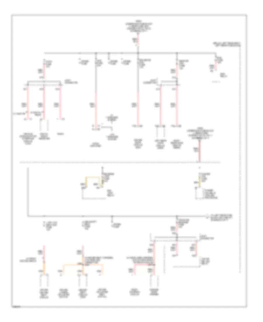
Power Distribution Wiring Diagram (6 of 7) for Cadillac CTS V 2006
List of elements for Power Distribution Wiring Diagram (6 of 7) for Cadillac CTS V 2006:
- (below right rear seat) right rear fuse block
- (early production)
- (except 5.7l) (5.7l)
- (in body harness, 108 cm from c700) s304
- (in body harness, 108 cm from c800) s303
- (in i/p harness, 11.5 cm from sp200) s200
- (in passenger seat harness, 12.7 cm from c307) s352
- A/t
- A/t shift lock control solenoid
- A11
- Automatic transmission shift lever
- Canister vent fuse 10a
- Ccp fuse 10a
- Dr mod pwr circuit breaker 30a
- Driver door module (ddm)
- Driver heated seat module
- Driver seat adjuster switch
- Evaporative emissions (evap) canister vent solenoid valve
- From ignition switch (pin 5) (diagram 4 of 7)
- From left rear fuse block (trk dr release fuse) (diagram 5 of 7)
- From underhood fuse block (r rear fuse) (connector c3, pin 2) (diagram 2 of 7)
- Front headlamp leveling sensor
- Front passenger door module (fpdm)
- Front passenger heated seat module
- Front passenger heated seat module (w/ front heated seats)
- Fuel pump motor relay
- Fuel pump mtr fuse 15a 20a
- G402 (rear of left rear shock tower)
- Hdlp leveling fuse 10a (if equipped)
- Hvac control module
- Ign 3 fuse 10a
- Ign 3 relay
- Ignition lock cylinder control actuator
- Ignition switch
- Joint connector
- Left rear door module (lrdm)
- Left rear fuse block (below left rear seat)
- Memory seat module (msm)
- Passenger lumbar adjuster switch
- Passenger seat adjuster switch
- R frt htd seat mod fuse 10a
- R21
- R22
- R23
- R25
- R37
- Rap relay
- Rear defog relay
- Rear headlamp leveling sensor
- Rear integration module
- Rear integration module (rim)
- Recirculation actuator
- Right rear door module (rrdm)
- Right rear fuse block (below right rear seat)
- Rim/ign sw fuse 10a
- Seat circuit breaker 30a
- Spare fuse
- Sunroof module
- Tan
- Underhood fuse block (right front of engine compt)
- W/ front heated seats
- W/ memory
- W/ passenger power seats
- W/ power lumbar control seats
- W/ power sliding sunroof
- W/o memory
- W/o passenger power seats
- W/o power lumbar control seats
Power Distribution Wiring Diagram (7 of 7) for Cadillac CTS V 2006
List of elements for Power Distribution Wiring Diagram (7 of 7) for Cadillac CTS V 2006:
- A12
- Abs fuse 10a
- Air bag fuse 10a
- Electronic brake control module (ebcm)
- From ignition switch (via splice pack sp200, pin 9) (diagram 4 of 7)
- From right rear fuse block (rim/ign sw fuse) (diagram 4 of 7)
- Front passenger door module (fpdm)
- G401 (rear of right rear shock tower)
- If equipped
- Ign 1 relay
- Inflatable restraint sensing & diagnostic module (sdm)
- Inside rear view mirror
- Int lamp relay
- Interior lamp fuse 10a
- Joint connector
- Pnk
- Psgr dr mod fuse 10a
- R16
- R17
- R21
- R22
- R23
- R25
- R31
- R32
- Rear defog fuse 40a
- Rear defog relay
- Rear fog lamp fuse 10a
- Rear fog lamp relay
- Rear integration module (rim)
- Right rear fuse block (below right rear seat)
- Rim fuse 10a
- S21
- S22
- S23
- Spare fuse

 Čeština
 Dansk
Dansk Deutsch
 Ελληνικά
 English
 English
 Suomi
Suomi Français
 Français
 עברית
עברית Hrvatski
 Magyar
 Italiano
 日本語
日本語 한국어
한국어 Nederlands
 Polski
 Português
 Português
 Română
 Русский
 Slovenčina
 Slovenščina
 Svenska
 Türkçe
 中文 (中国)