БЛОК ПРЕДОХРАНИТЕЛЕЙ И РЕЛЕ
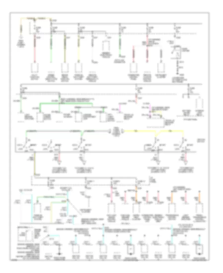
Электросхема блока предохранителей и реле (1 из 3) для Ford Taurus LX 1998


Электросхема блока предохранителей и реле (1 из 3) для Ford Taurus LX 1998 - Список элементов:
- (body harn, below driver's seat)
- (engine harness, near exhaust manifold) s148
- 10a
- 175a
- 3.4l sho
- A/c clutch relay
- Air bag diagnostic monitor
- Anti-lock brake control module
- Autolamp headlamp relay
- Autolamp park relay
- Battery
- Battery saver relay
- Blower motor relay
- Cellular phone in-line fuse (above left rear wheel well)
- Cellular phone transceiver
- Circuit breaker 30a
- Compact disc changer
- Daytime running lamps module (w/ drl only)
- Eam solid state relay
- Engine compartment fuse/relay box
- Fuel pump relay
- Fuse 10a
- Fuse 15a
- Fuse 20a
- Fuse 30a
- Fuse 40a
- Generator/ voltage regulator
- Headlamp switch
- High speed cooling fan relay
- Horn relay
- Interior lamp relay
- Left lumbar seat switch
- Left seat control switch
- Low speed cooling fan relay
- Mega fuse (right side of eng compt)
- Multi- function switch
- Nca
- Pcm relay
- Powertrain control module
- Rear control unit
- Red
- S128 (dash panel to headlamp harn, near breakout to engine compartment fuse box)
- S132 (engine harn, left of battery)
- S139
- S141 (engine harness, left of battery)
- S143 (dash to headlamp harness, near engine cooling fan 1))
- S414 (body harn, left rear wheelwell)
- S423 (body harn, left rear wheelwell)
- Semi-active ride control module
- Starter motor/ relay
- Starter relay
- Tan/red
- Thermactor air bypass solenoid
- To fuse 29 (i/p fuse panel) (diagram 2 of 3)
- To i/p fuse panel (accessory delay relay) (diagram 3 of 3)
- To ignition switch (pins b1 & b3) (diagram 2 of 3)
- To ignition switch (pins b4 & b5) (diagram 2 of 3)
- To rear window defrost relay (i/p fuse panel) (diagram 3 of 3)
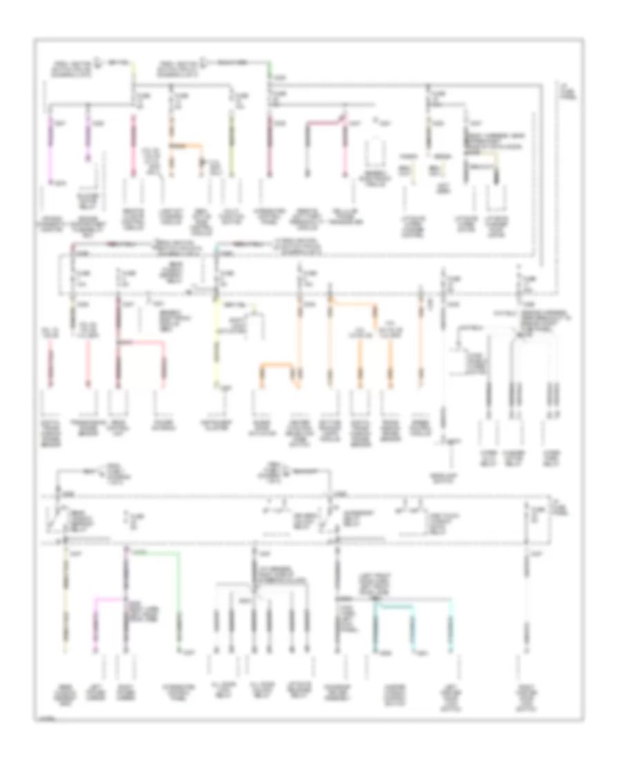
Электросхема блока предохранителей и реле (2 из 3) для Ford Taurus LX 1998
Электросхема блока предохранителей и реле (2 из 3) для Ford Taurus LX 1998 - Список элементов:
- (body harness, near breakout to left rear door jamb switch) s313
- (engine harness, near breakout to ignition coil no 5 & no 6) s161
- (engine harness, near breakout to left headlamp)
- (engine harness, near breakout to radio noise capacitor) (others) (engine harness, near breakout to heated oxygen sensor) (24 valve engine)
- (i/p fuse panel) (diagram 3 of 3)
- (i/p harness, left side of dash) s224
- (i/p harness, near center of dash) s211
- (lower side of inner glove box frame)
- 12-valve
- 20a
- 3.0l 24- valve
- 3.0l 24-valve & 3.4l sho only
- 3.4l sho
- 3.ol 12-valve
- Acc
- Anti- theft disarm switch
- Anti-lock brake control module
- Battery saver relay
- Brake pedal position switch
- C201
- C211
- C212
- C225
- C229
- C235
- C236
- C238
- C247
- C250
- C251
- C254
- Cigar lighter
- Data link connector
- Engine compt fuse/ relay box
- Except 3.ol
- Ffv only
- Flex fuel sender module
- From fuse 1 (diagram 1 of 3)
- From fuses 3 and 5 (diagram 1 of 3)
- Fuse
- Fuse 10a
- Fuse 11 5a
- Fuse 12 5a
- Fuse 15a
- Fuse 20a
- Fuse 5a
- Fuse 9 10a
- G206
- Generic electronic module
- Generic electronic module (gem)
- Glove box) s216
- I/p fuse panel
- Ignition coil
- Ignition coil no
- Ignition switch
- Instru- ment cluster
- Instrument cluster
- Integrated control panel
- Integrated control panel (icp)
- Interior lamp relay
- Light sensor/ amplifier
- Lock
- Luggage compartment lamp
- Multi- function switch
- Off
- Passive anti-theft system
- Pcm diode
- Power antenna
- Power mirror switch
- Prndl/ transmission control illumination
- Radio noise capacitor
- Radio noise capacitor no1
- Radio noise capacitor no2
- Remote anti-theft personality module
- Remote climate control module
- Run
- S112
- S122
- S163 (engine harness, near breakout to radio noise capacitor)
- S212
- Sedan
- Speed control deactivate switch
- Sta
- Start
- To fuses 13, 14 & 15 (i/p fuse panel) (diagram 3 of 3)
- To fuses 17, 18, 19 & 20 (i/p fuse panel) (diagram 3 of 3)
- To fuses 5 & 6
- To fuses 7 & 8 (i/p fuse panel) (diagram 3 of 3)
- Transmission control switch
- Trunk lid release relay
- W/ abs only
- W/ rap
- W/o rap
- Wagon
Электросхема блока предохранителей и реле (3 из 3) для Ford Taurus LX 1998
Электросхема блока предохранителей и реле (3 из 3) для Ford Taurus LX 1998 - Список элементов:
- (body harness, near upper right side of hatch door) s409
- (i/p harness, right side of steering column)
- (left front door harn, left front door jamb)
- (not used)
- 24-valve 3.4l sho
- 3.0l
- 3.0l 12- valve
- 3.0l 12-valve
- 3.0l 24- valve & 3.4l sho only
- 3.0l 24- valve 3.4l sho
- 3.4l sho only
- Accessory delay relay
- Air bag diagnostic monitor
- All door lock relay
- All door unlock relay
- Blend door actuator
- Blower motor relay
- C201
- C2031
- C225
- C235
- C237
- C247
- C251
- C276
- C501
- C509
- Cellular phone transceiver
- Daytime running lamps module
- Digital trans- mission range sensor
- Driver's unlock relay
- Engine compartment fuse/relay box
- From ignition g
- From ignition h
- From fuse 4 (diagram 1 of 3)
- From fuse 7 (diagram 1 of 3)
- From ignition switch (pin a3) (diagram 2 of 3)
- From ignition switch (pin sta) (diagram 2 of 3)
- Fuse 10a
- Fuse 15a
- Fuse 30a
- Fuse 5a
- Generic electronic module
- Generic electronic module (gem)
- Headlamp switch
- Heater function selection mode switch
- I/p fuse panel
- Instrument cluster
- Integrated control panel
- Lamp out warning module
- Left master door lock switch
- Left power mirror
- Liftgate release relay
- Liftgate washer pump motor
- Liftgate wiper motor
- Liftgate wiper/ washer control
- Main harn, left kick panel)
- Master window control switch
- Moonroof driver assembly
- Multi- function switch
- Nca
- Near breakout to engine compt fuse panel) s140
- One touch window down relay
- Power antenna
- Rear control unit
- Rear window defrost grid
- Rear window defrost relay
- Remote anti-theft personality module
- Remote climate control module
- Right master door lock switch
- Right power mirror
- S203
- S204
- S309 (body harn, left front door jamb)
- S413
- S440
- S504
- Sedan
- Semi- active ride control module
- Shift lock actuator
- Speed control module
- Switch (pin a1) (diagram 2 of 3)
- Switch (pin a4) (diagram 2 of 3)
- Trans- mission range sensor
- Transmission range sensor
- Wagon
- Washer motor relay
- Wind- shield wiper motor
- Wiper hi/lo relay
- Wiper park relay

 Čeština
 Dansk
Dansk Deutsch
 Ελληνικά
 English
 English
 Suomi
Suomi Français
 Français
 עברית
עברית Hrvatski
 Magyar
 Italiano
 日本語
日本語 한국어
한국어 Nederlands
 Polski
 Português
 Português
 Română
 Русский
 Slovenčina
 Slovenščina
 Svenska
 Türkçe
 中文 (中国)