БЛОК ПРЕДОХРАНИТЕЛЕЙ И РЕЛЕ
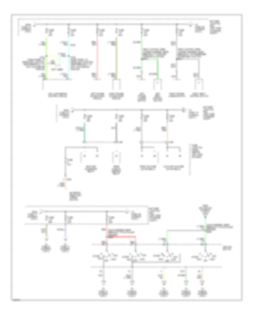
Электросхема блока предохранителей и реле (1 из 4) для Ford Windstar 2000


Электросхема блока предохранителей и реле (1 из 4) для Ford Windstar 2000 - Список элементов:
- (dash panel to headlamp harness, near breakout to left front wheel speed sensor) s123
- (dash panel to headlight junction, left rear of engine compt) s130
- (dash panel to headlight junction, near breakout to battery junction box) s127
- (starter motor relay & battery ground harness, near breakout for mass airflow sensor)
- (starter motor relay & battery ground harness, near breakout for mass airflow sensor) s142
- 2 of 4)
- A/c clutch relay
- Battery
- Battery junction box (left side of engine compt)
- C190
- C348
- Dual auxiliary relay box (at left rear side of engine compt)
- Electronic brake switch connector
- Engine cooling fan motor high speed relay
- Engine cooling fan motor low speed relay
- From fuse 105 (diagram 1 of 4)
- From fuse 6 (diagram 1 of 4)
- Front electronic module
- Fuel pump relay
- Fuse 10a
- Fuse 15a
- Fuse 25a
- Fuse 30a
- Fuse 50a
- Generator
- Horn relay
- Liftgate washer pump motor
- Liftgate wiper motor
- Liftgate wiper relay
- Pcm power relay
- Powertrain control module
- Red
- S124 (dash panel to headlamp harness, near breakout to left front wheel speed sensor)
- S126
- S141
- S143
- Starter interrupt relay
- Starter motor/ solenoid
- To fuse 102 (diagram 2 0f 4)
- To fuse 2 (diagram 1 of 4)
- To fuse 7 (diagram 1 of 4)
- To splice s226 (diagram
- Windshield washer pump motor
- Windshield wiper motor
- Windshield wiper on/ off relay
- Windshield wiper speed relay
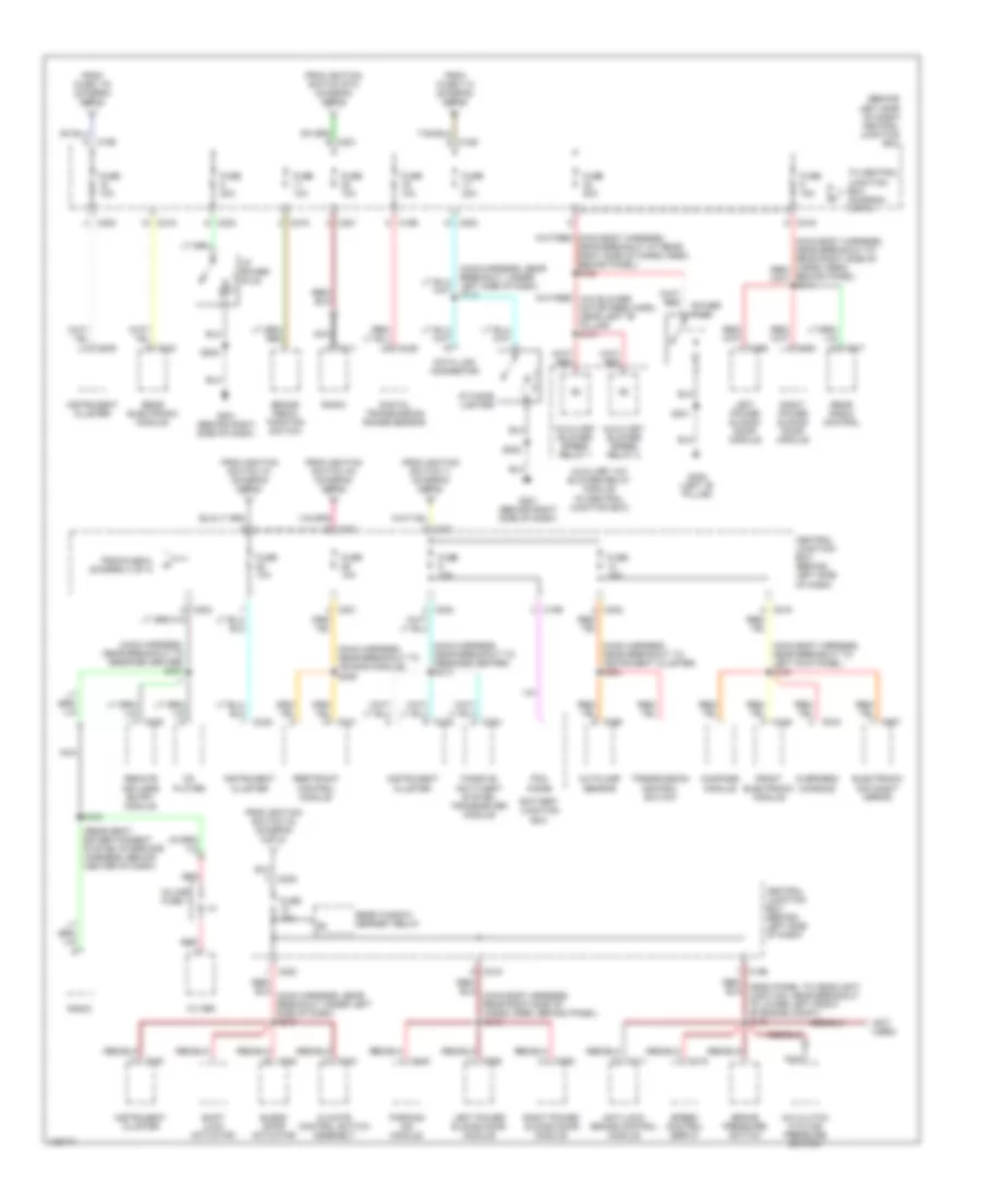
Электросхема блока предохранителей и реле (2 из 4) для Ford Windstar 2000
Электросхема блока предохранителей и реле (2 из 4) для Ford Windstar 2000 - Список элементов:
- (not used)
- (seat control feed jumper harness, near breakout to driver horizontal motor) s340
- (seat control feed jumper harness, near breakout to passenger power seat switch) s341
- Acc
- Anti-lock brake control module
- Auxiliary blower motor relay
- Battery junction box (left side of engine compt)
- C195
- C196
- C220
- Delayed accessory relay
- Exterior rear view mirror switch
- From fuse 104 (diagram 2 of 4)
- From fuse 112 (diagram 1 of 4)
- From fuse 117 (diagram 2 of 4)
- From splice s124 (diagram 1 of 4)
- Front blower motor relay
- Fuse 10a
- Fuse 20a
- Fuse 30a
- Fuse 40a
- Fuse 50a
- Fuse junction panel (behind left side of dash)
- Ignition switch
- Left power lumbar switch
- Left power sliding door module
- Left seat control switch
- Lock
- Lock off
- Nca
- Off
- Rear window defrost relay
- Red (main harness, near breakout to autolamp sensor) s225
- Red b1
- Red b3
- Right power lumbar switch
- Right power sliding door module
- Right seat control switch
- Run
- S128 (dash panel to headlamp junction, near breakout to anti-lock brake module)
- S129 (dash panel to headlamp junction, near breakout to anti-lock brake module)
- Sta
- Start
- To fuse 10 (diagram 3 of 4)
- To fuse 106 (diagram 2 of 4)
- To fuse 109 (diagram 4 of 4)
- To fuse 115 (diagram 2 of 4)
- To fuse 16 (diagram 3 of 4)
- To fuse 23 (diagram 3 of 4)
- To fuse 25 (diagram 3 of 4)
- To fuse 26 (diagram 3 of 4)
- To fuse 28 (diagram 3 of 4)
- To fuse 9 (diagram 3 of 4)
Электросхема блока предохранителей и реле (3 из 4) для Ford Windstar 2000
Электросхема блока предохранителей и реле (3 из 4) для Ford Windstar 2000 - Список элементов:
- (behind left side of dash) central junction box
- (main body harness, near breakout to left kick panel) s330
- (main harness, near breakout to air bag module) s209
- (main harness, near breakout to instrument cluster) s224
- (main harness, near breakout to message center) s207
- (main harness, near breakout to message center) s216
- (not used)
- (rear seat entertainment system interface harness, behind center of dash)
- A/c clutch cycling pressure switch
- Anti-lock brake control module
- Autolamp sensor
- Auxiliary a/c blower relay module (in central junction box)
- Auxiliary blower speed relay 1
- Auxiliary blower speed relay 2
- Battery junction box
- Blend door actuator
- Brake pedal position switch
- Brake pressure switch
- C116
- C126
- C195
- C196
- C200
- C201
- C202
- C211
- C219
- C231
- C239
- C240
- C244
- C260
- C343
- C346
- C352
- C355
- C445
- C907
- C915
- C917
- Cd player
- Central junction box (behind left side of dash)
- Climate control switch assembly
- Compass module
- Data link connector
- Digital transmission range sensor
- Electronic day/night mirror
- Filter
- From fuse 115 (diagram 2 of 4)
- From fuse 119 (diagram 2 of 4)
- From fuse 6, (diagram 3 of 4)
- From ignition switch a1 (diagram 2 of 4)
- From ignition switch a3 (diagram 2 of 4)
- From ignition switch a4 (diagram 2 of 4)
- From ignition switch i1 (diagram 2 of 4)
- From ignition switch sta (diagram 2 of 4)
- Front electronic module
- Fuse 10a
- Fuse 15a
- Fuse 20a
- G201 (behind right side of dash)
- G308 (left "b" pillar)
- I/p cigar lighter
- I/p power plug
- In-line fuse 1
- Instrument cluster
- Left power sliding door module
- Left side of dash) s218
- Nca
- Overhead console
- Parking aid module
- Passive anti-theft system transceiver module
- Pcm diode
- Power plug
- Radio
- Rear electronic module
- Rear radio control
- Rear window defrost relay
- Red
- Remote keyless entry module
- Restraint control module
- Right power sliding door module
- S202
- S208
- S301
- S350
- Shift lock actuator
- Speed control servo
- To central junction box (diagram 3 of 4)
- Transmission control switch
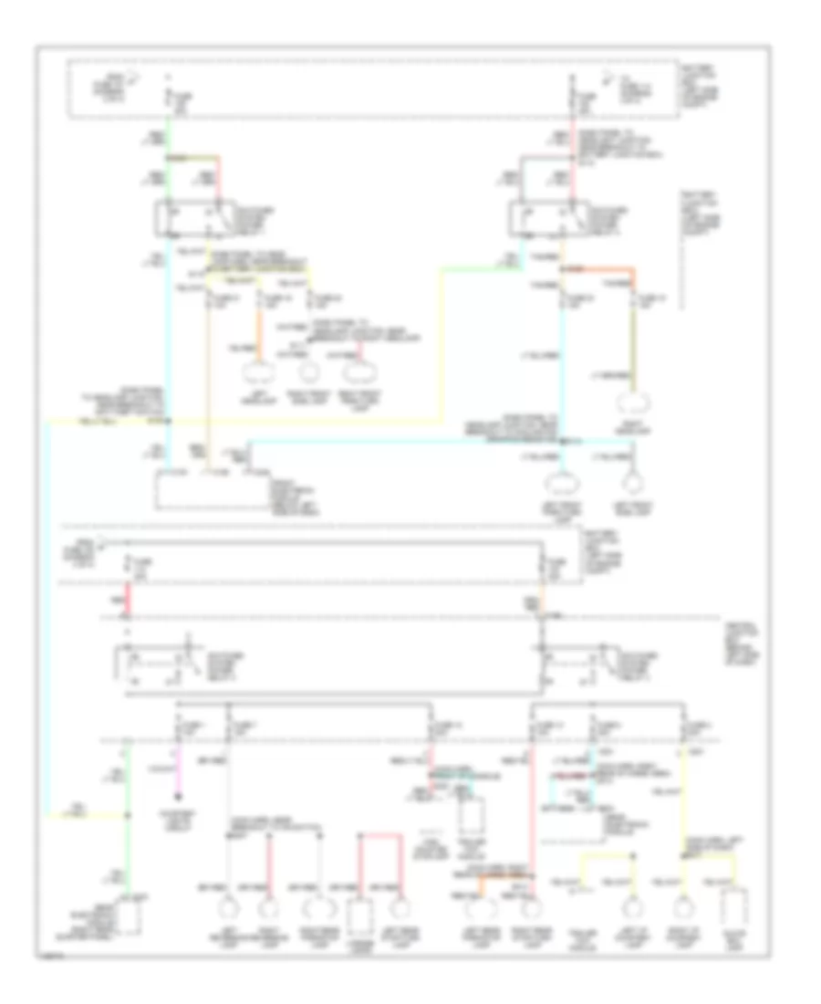
Электросхема блока предохранителей и реле (4 из 4) для Ford Windstar 2000
Электросхема блока предохранителей и реле (4 из 4) для Ford Windstar 2000 - Список элементов:
- (dash panel to headlamp junction, near breakout to anti-theft switch)
- (dash panel to headlamp junction, near breakout to cooling fan dropping resistor)
- (dash panel to headlight junction, near breakout to battery junction box) s118
- (main harn, front of console)
- (main harn, left side of dash) s217
- (main harn, near breakout to ifs switch) s307
- (main harn, right rear of cargo area)
- Battery junction box (left side of engine compt)
- C191
- C192
- C196
- C201
- C221
- C342
- C343
- C344
- C346
- Central junction box (behind left side of dash)
- Courtesy lights circuit
- From p fuse 121 (diagram 2 of 4)
- From q fuse 108 (diagram 4 of 4)
- Front electronic module (below left side of dash)
- Fuse 1 10a
- Fuse 12 20a
- Fuse 13 15a
- Fuse 15 15a
- Fuse 16 15a
- Fuse 2 20a
- Fuse 21 10a
- Fuse 22 15a
- Fuse 23 15a
- Fuse 40a
- Fuse 7 15a
- Fuse 8 20a
- Glove box lamp
- High mounted stoplamp
- Left front park/turn lamp
- Left front side lamp
- Left headlamp
- Left i/p courtesy lamp
- Left rear park/stop lamp
- Left rear stop/turn lamp
- Left reversing lamp
- License lamps
- Rear electronic module
- Rear electronic module (right rear quarter panel)
- Red
- Right front park/turn lamp
- Right front side lamp
- Right headlamp
- Right i/p courtesy lamp
- Right rear park/stop lamp
- Right rear stop/turn lamp
- Right reversing lamp
- S111
- S114
- S119
- S120
- S121
- S135
- S314
- Switched system power relay 1
- Switched system power relay 2
- Switched system power relay 3
- Switched system power relay 4
- Tan/red
- To fuse 114 (diagram 4 0f 4)
- Trailer tow module

 Čeština
 Dansk
Dansk Deutsch
 Ελληνικά
 English
 English
 Suomi
Suomi Français
 Français
 עברית
עברית Hrvatski
 Magyar
 Italiano
 日本語
日本語 한국어
한국어 Nederlands
 Polski
 Português
 Português
 Română
 Русский
 Slovenčina
 Slovenščina
 Svenska
 Türkçe
 中文 (中国)