ENGINE PERFORMANCE
5.4L
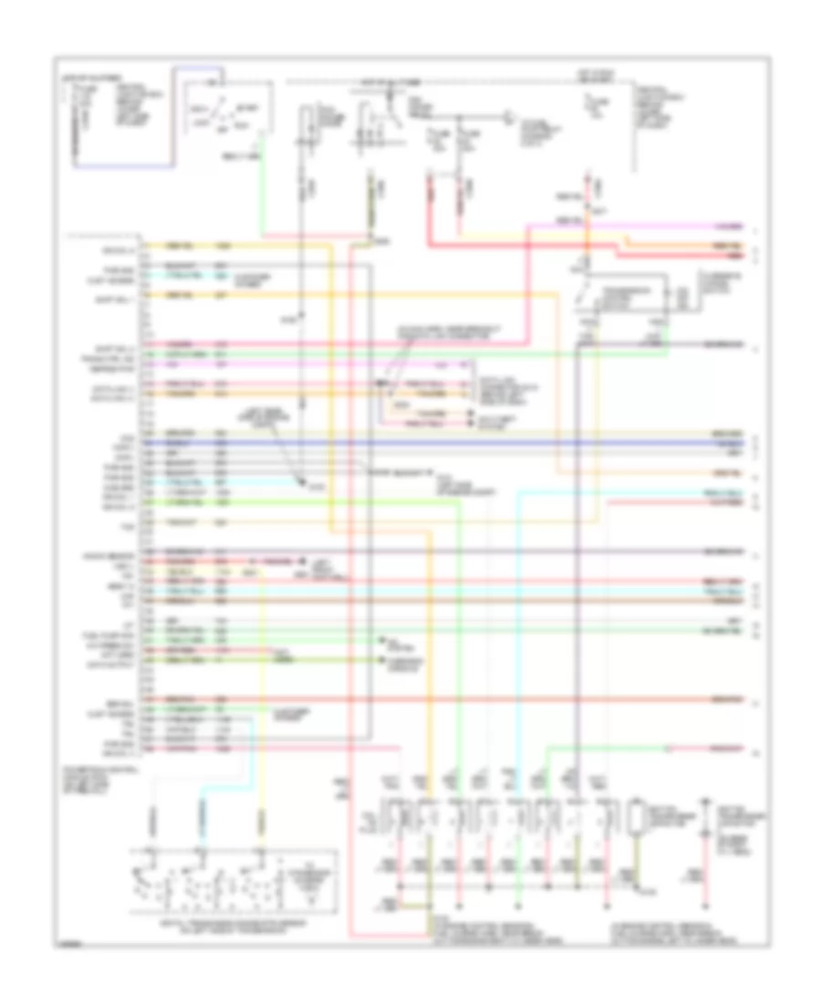
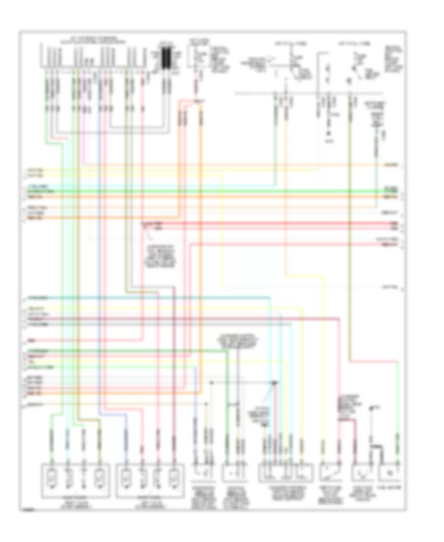
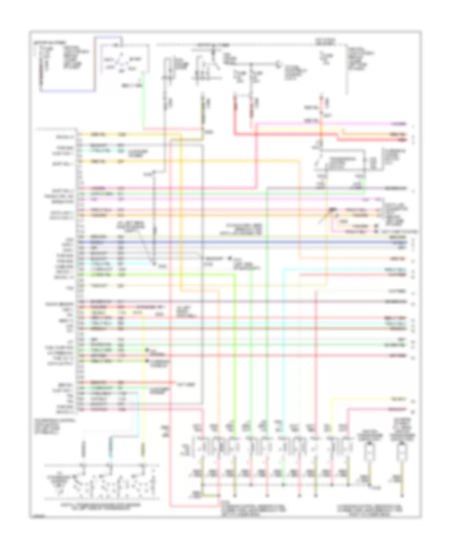
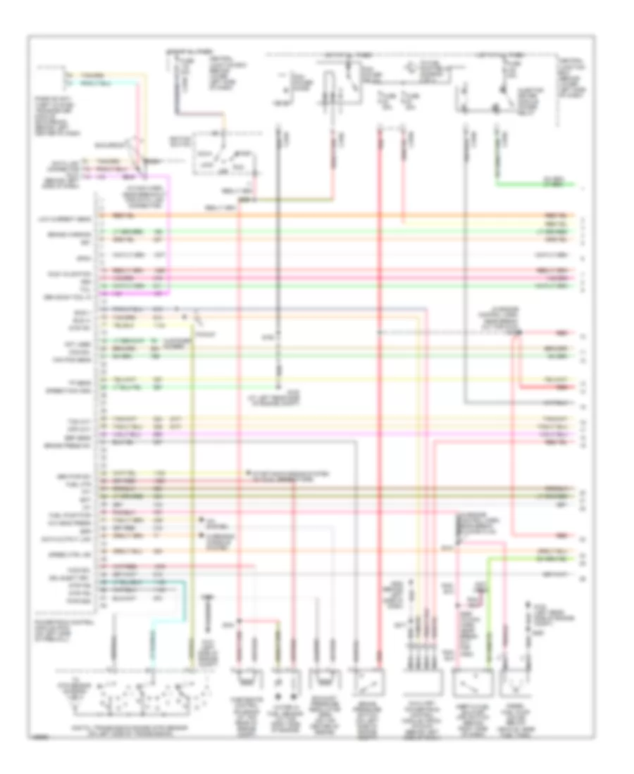
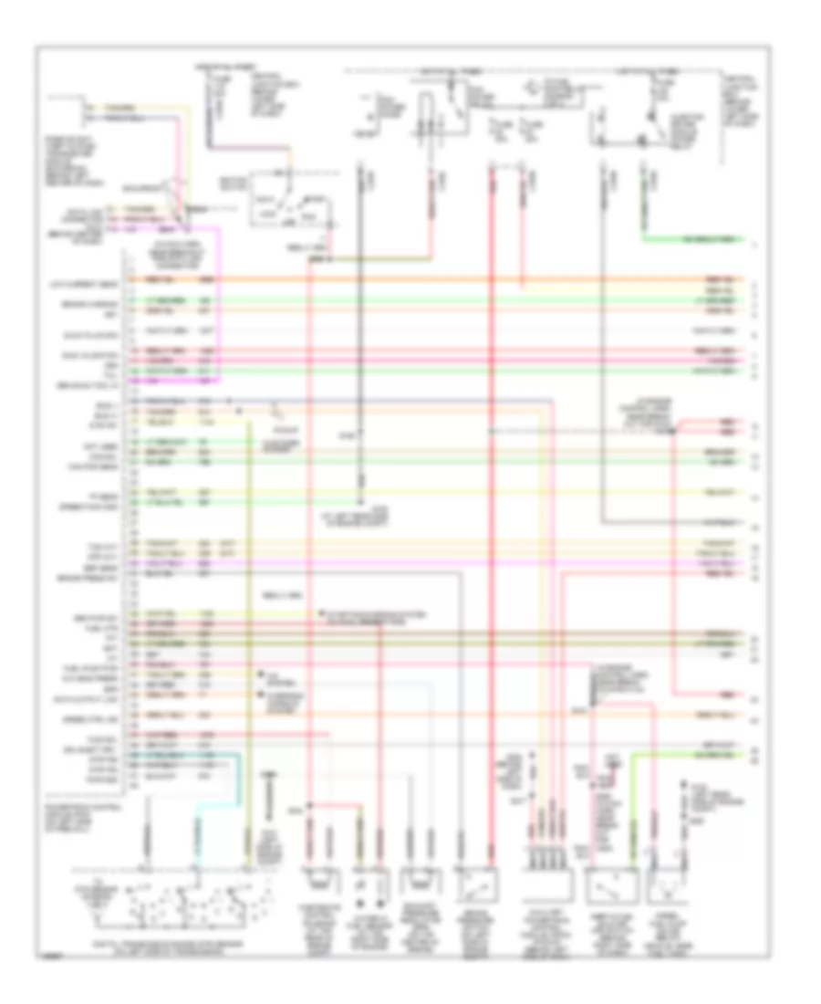
5.4L, Engine Performance Wiring Diagram (1 of 4) for Ford Cab & Chassis F350 Super Duty 2003
List of elements for 5.4L, Engine Performance Wiring Diagram (1 of 4) for Ford Cab & Chassis F350 Super Duty 2003:
- (in engine control sensor & fuel charge harn, near break- out for engine left cylinder head)
- (in main harn, near breakout for data link connector)
- (left front g300 footwell)
- (left rear side of engine compt)
- (not used)
- A/c press sw
- A/c system
- Acc
- Anti-theft system
- C270a
- Ccs
- Central junction box (behind lower left side of dash)
- Ckp(+)
- Ckp(-)
- Coil on plug
- Cust access
- Customer access
- Data link (+)
- Data link (-)
- Data link connector (dlc) (behind left side of dash)
- Data output
- Diag grd
- Digital transmission range (dtr) sensor (on left side of transmission)
- Egr sol
- Fuel pump mon
- Fuse 10a
- Fuse 20a
- Fuse 30a
- G100
- G101 (left side of engine compt)
- Hego 12
- Hot at all times
- Hot in run or start
- Iat
- Ign coil 1
- Ign coil 3
- Ign coil 5
- Ign coil 6
- Ignition transformer capacitor
- Ignition transformer capacitor (on rear of right cyl head)
- Knock sensor
- Lock
- Maf
- Nca
- Not used
- O/d off ind
- Off
- Overdrive cancel switch
- Overhead console
- Pcm power diode
- Pcm power relay
- Powertrain control module (pcm) (on left side of firewall)
- Pwr gnd
- R n
- Red
- Reprog pwr
- Run
- S106
- S130 (in engine control sensor & fuel charge harn, near break- out for engine right cylinder head)
- S135
- S162
- S201
- S258
- S271
- S284
- S286
- Shift sol 1
- Shift sol 2
- Start
- Tcs
- Tft
- To dtr sensor (diagram 4 of 4)
- To fuel pump relay (diagram 2 of 4)
- Tr1
- Tr2
- Tr4
- Trans ctrl ind
- Transmission control switch
- Vss (-)
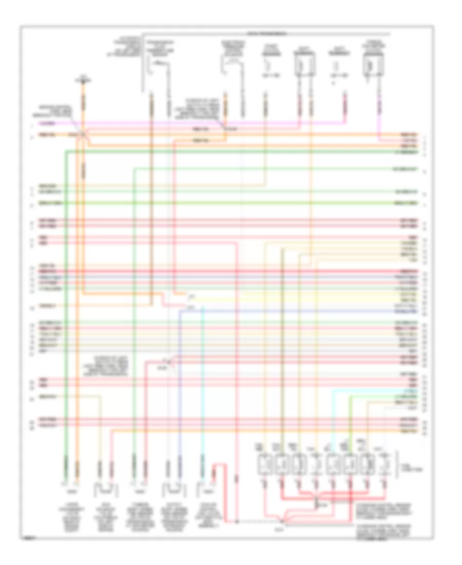
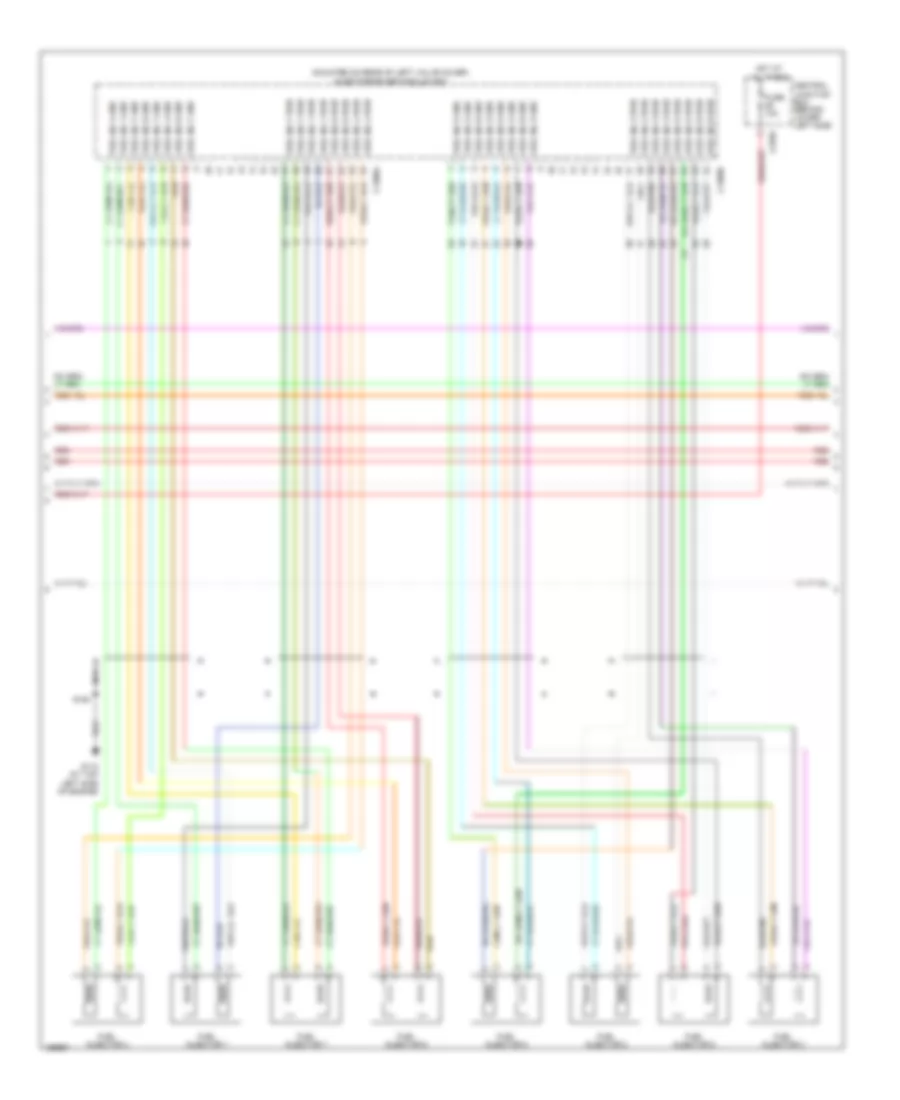
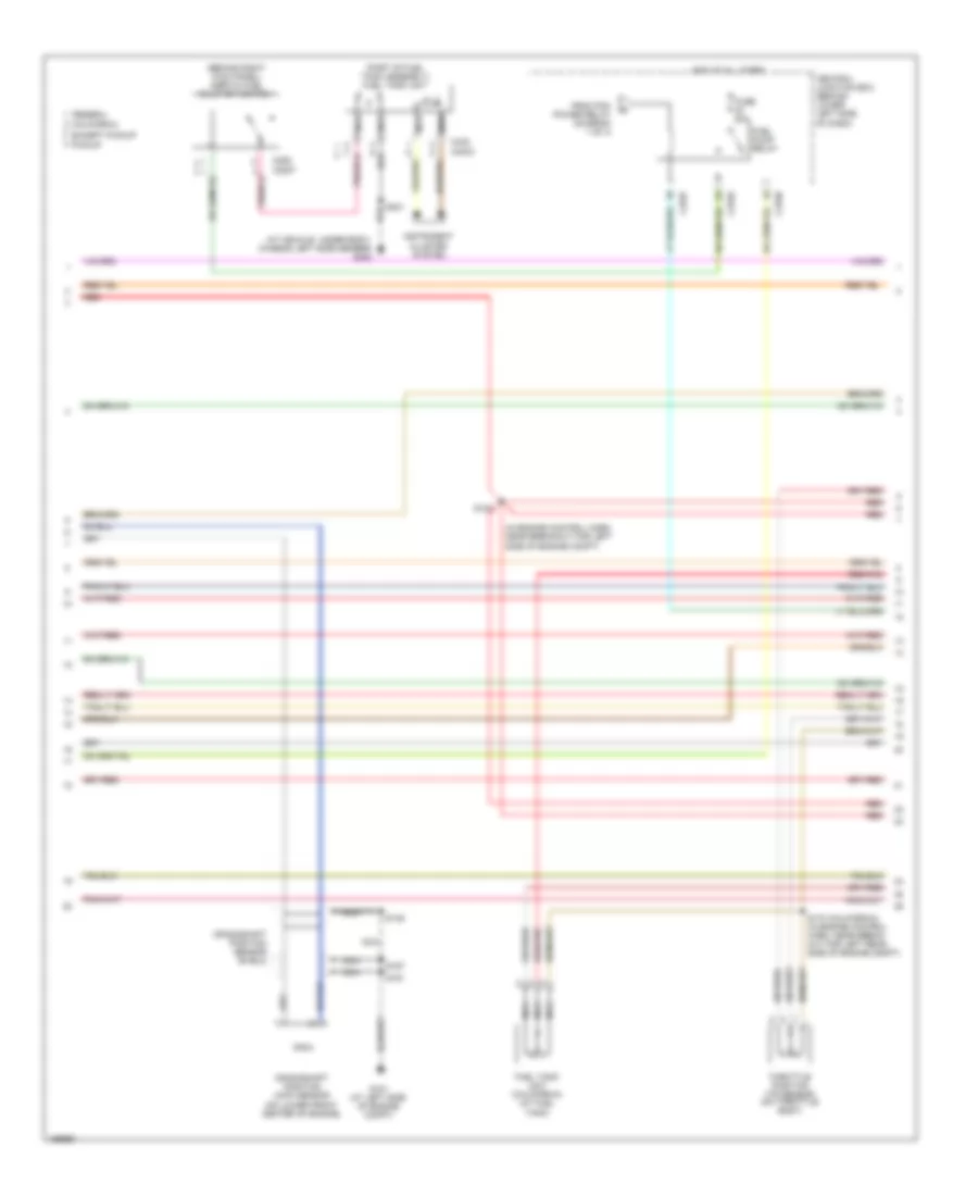
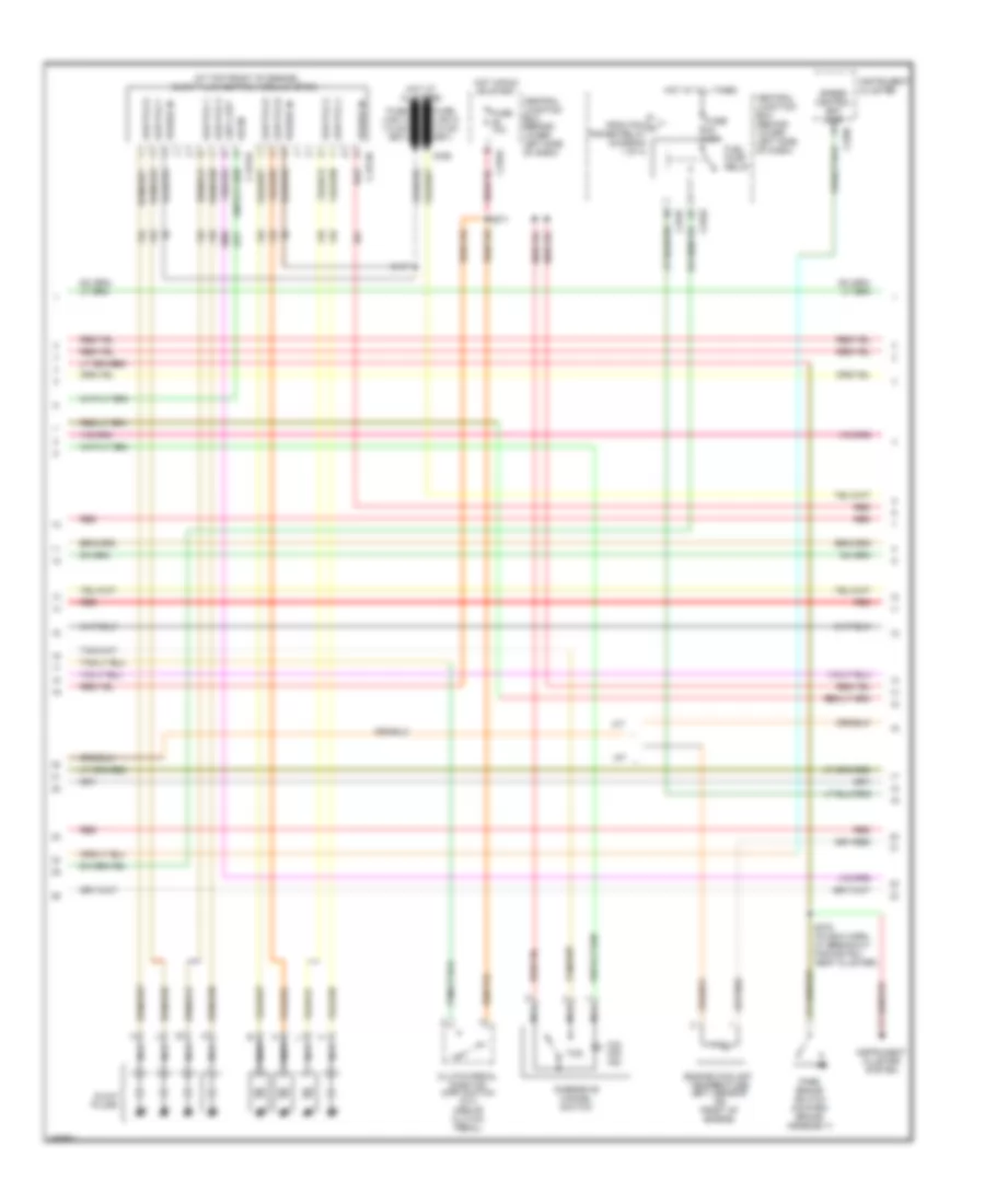
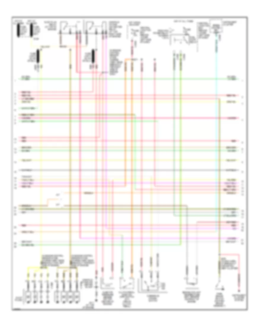
5.4L, Engine Performance Wiring Diagram (2 of 4) for Ford Cab & Chassis F350 Super Duty 2003
List of elements for 5.4L, Engine Performance Wiring Diagram (2 of 4) for Ford Cab & Chassis F350 Super Duty 2003:
- (behind right side of dash) inertia fuel shut-off switch
- (engine harness, near breakout for left side of engine compt)
- (part of fuel tank assembly) fuel tank unit
- C2207
- C270a
- C270f
- C270h
- C282
- C4033
- C433
- California
- Central junction box (behind lower left side of dash)
- Crankshaft position (ckp) sensor (on lower front center of engine)
- Crankshaft position sensor shield
- Differential pressure feedback egr (dpfe) sensor (california) (at top of engine)
- Except pickup
- Federal
- From pcm power relay (diagram 1 of 4)
- Fuel pump relay
- Fuel tank unit (california) (at fuel tank)
- Fuse 20a
- G101 (left side of engine compt)
- Hot at all times
- Instrument cluster system
- Nca
- Pickup
- Red
- Red/pnk
- S123
- S133 (california) (in engine control sensor & fuel charge harn, near breakout for engine right cylinder head)
- S145
- S161
- S167
- S401
- Throttle position (tp) sensor (on throttle body)
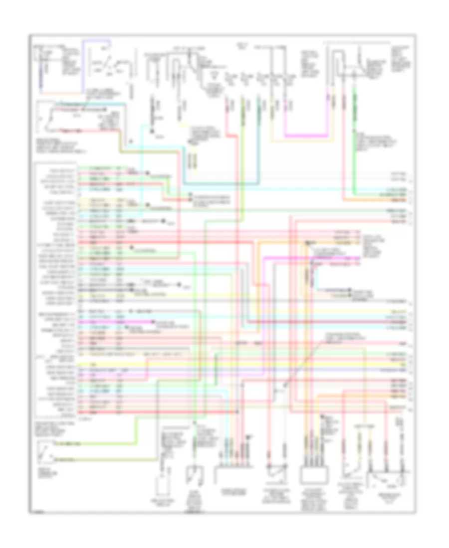
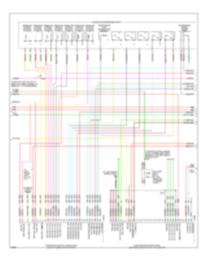
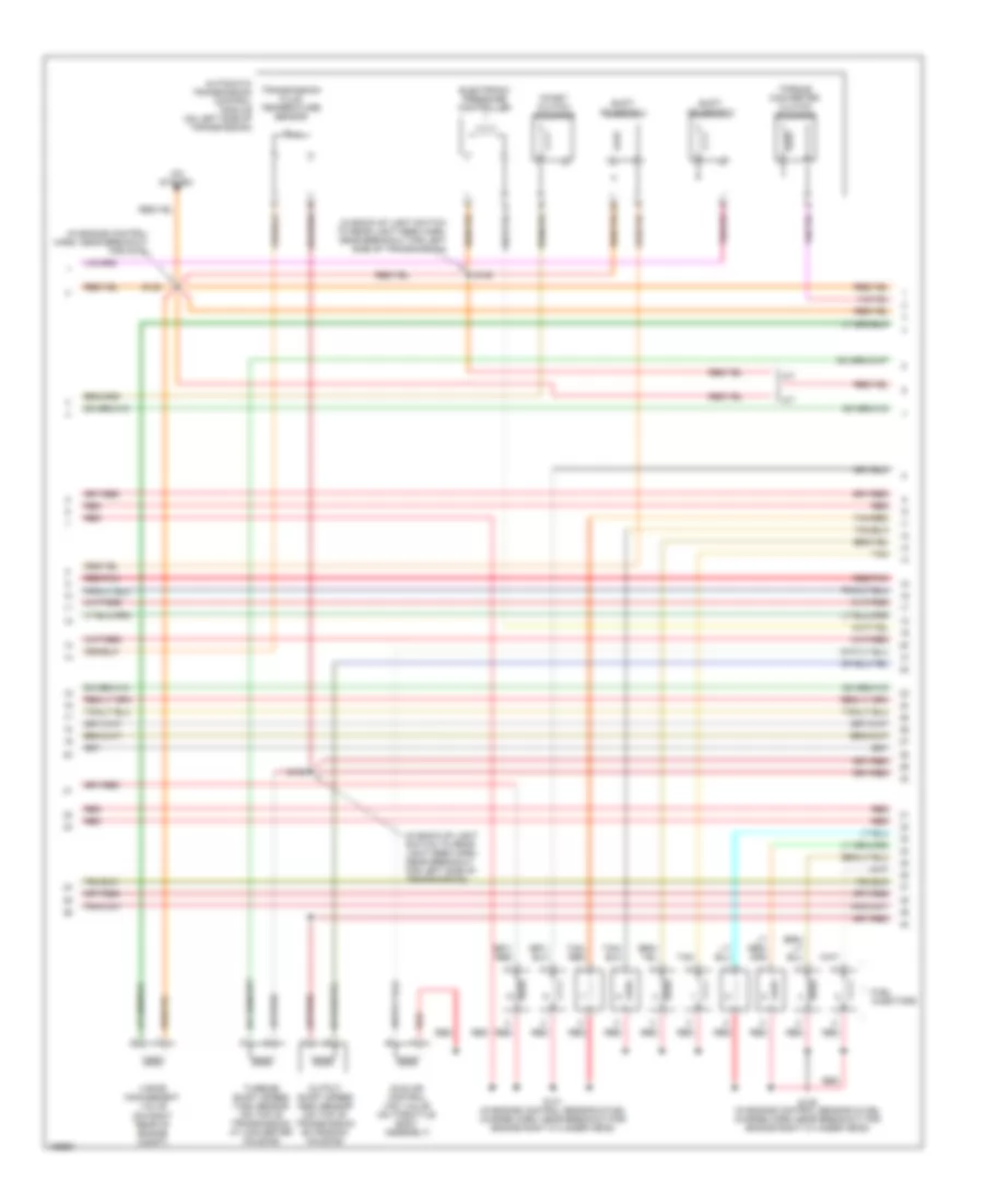
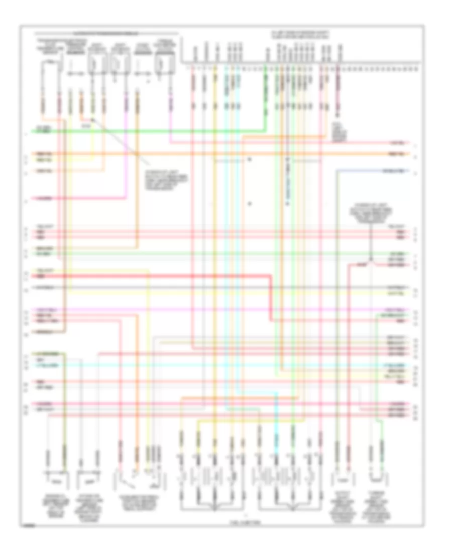
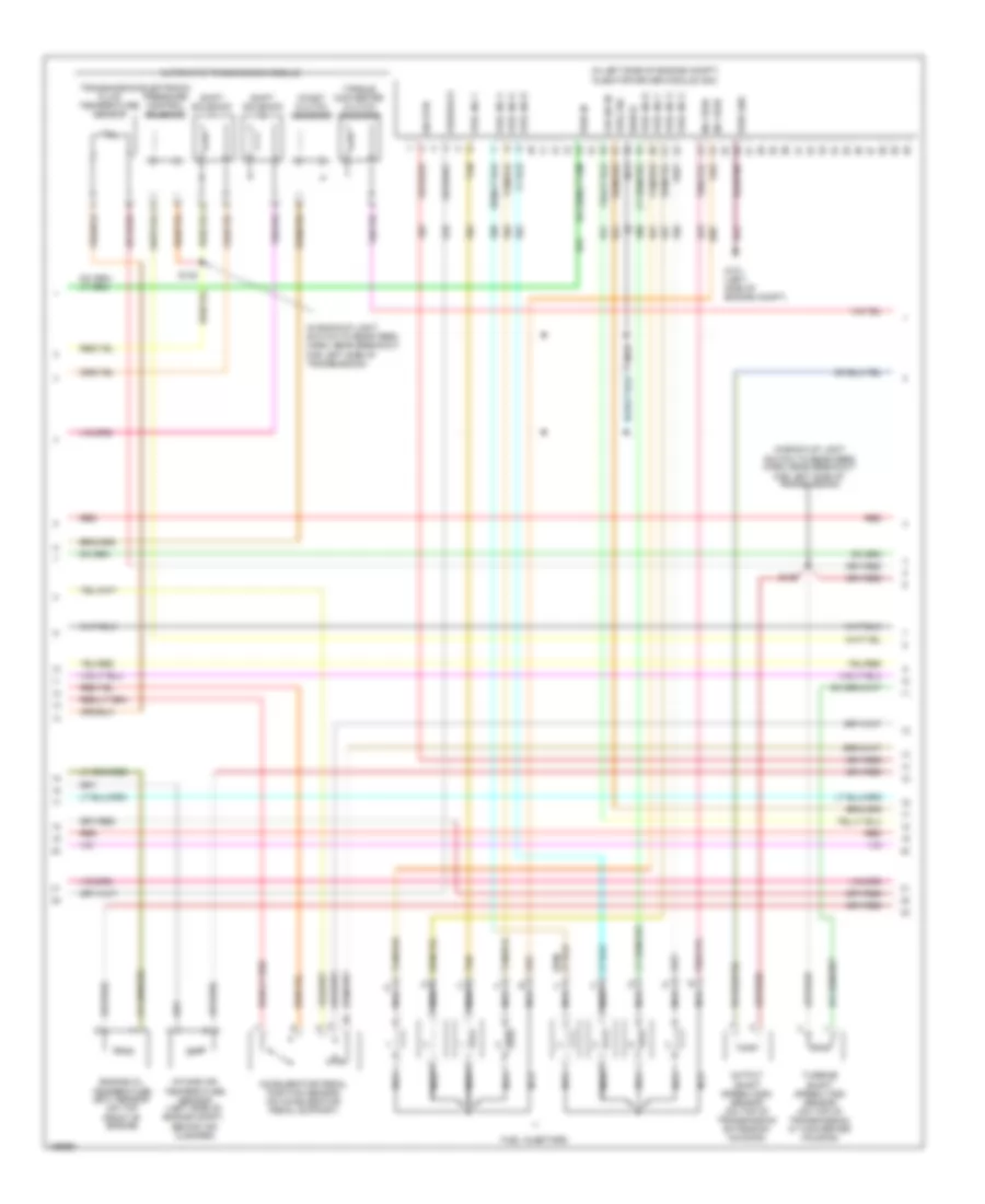
5.4L, Engine Performance Wiring Diagram (3 of 4) for Ford Cab & Chassis F350 Super Duty 2003
List of elements for 5.4L, Engine Performance Wiring Diagram (3 of 4) for Ford Cab & Chassis F350 Super Duty 2003:
- (engine control harn, near breakout for g100)
- (in back-up light switch to rear light feed harn, near breakout for left side of transmission)
- (in engine control sensor & fuel charge harn, near breakout for engine left cylinder head)
- (in engine control sensor & fuel charge harn, near breakout for engine right cylinder head)
- (on right rear of engine compt)
- 4r100 transmission
- A/c system
- A/t
- Automatic transmission module (on left side of transmission)
- Coast clutch solenoid
- Electronic pressure control solenoid
- Evr solenoid valve (california) (on left side of engine)
- Fuel injectors
- Idle air control (iac) valve (on throttle body assembly)
- M/t
- Output shaft speed (oss) sensor (on top of transmission extension housing)
- Red
- Red/pnk
- S122
- S131
- S136
- S138
- S139
- Shift solenoid 1
- Shift solenoid 2
- Tan
- Tan/ red
- Tan/red
- Torque converter clutch solenoid
- Transmission fluid temperature sensor
- Turbine shaft speed (tss) sensor (on top of transmission, at converter housing)
- Vapor management valve
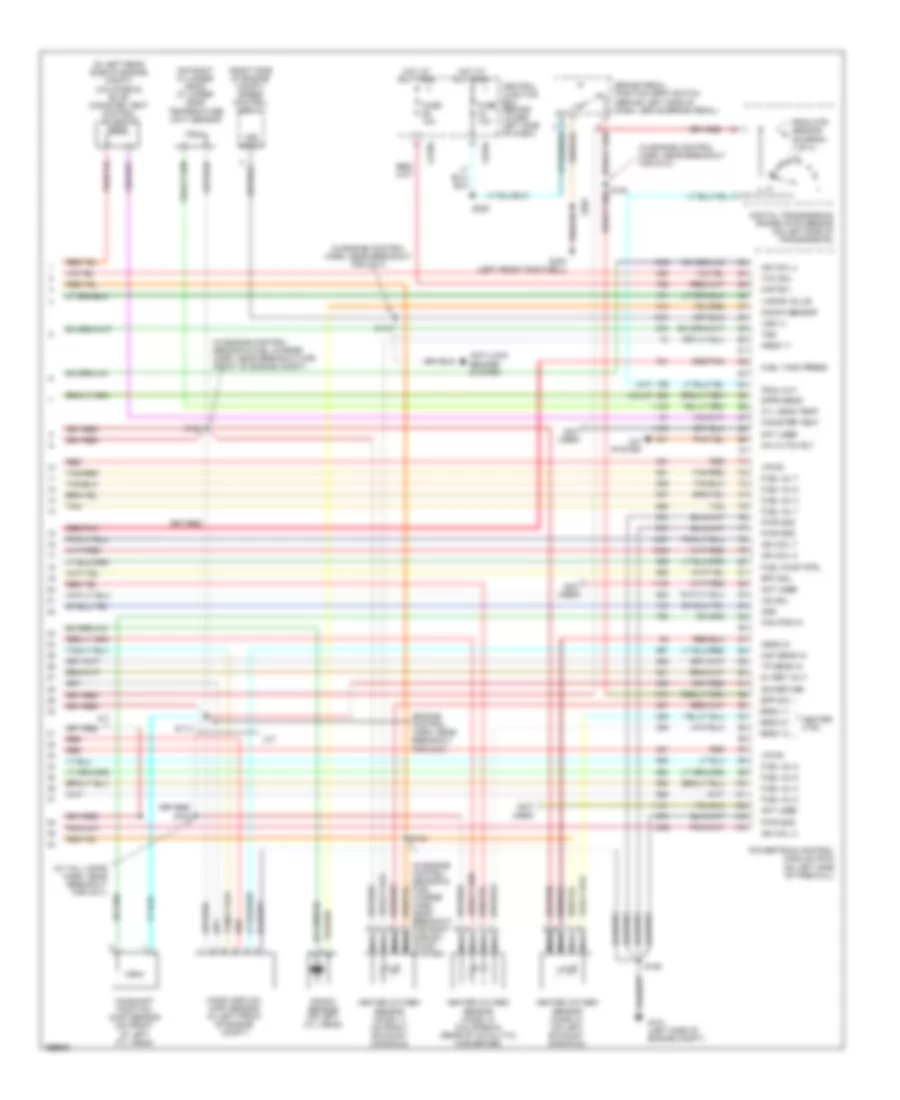
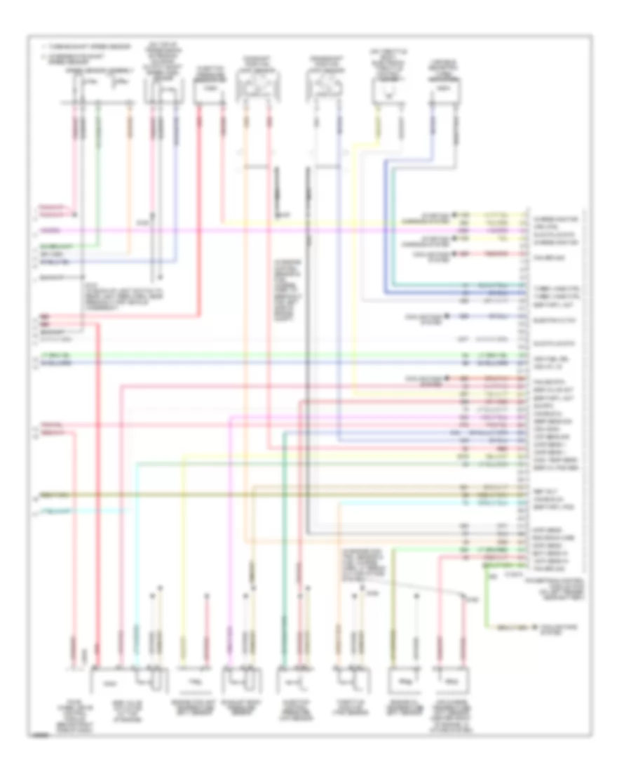
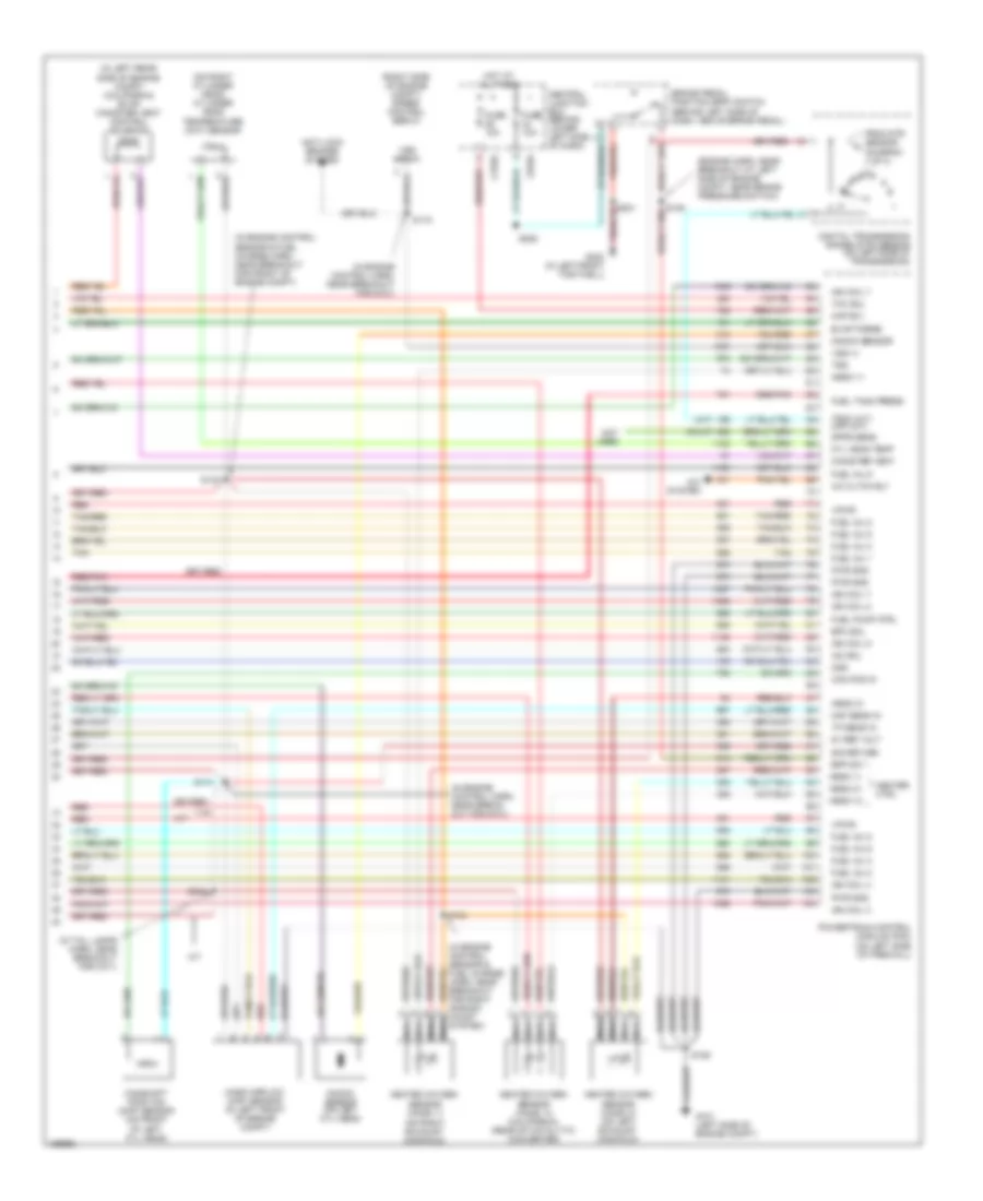
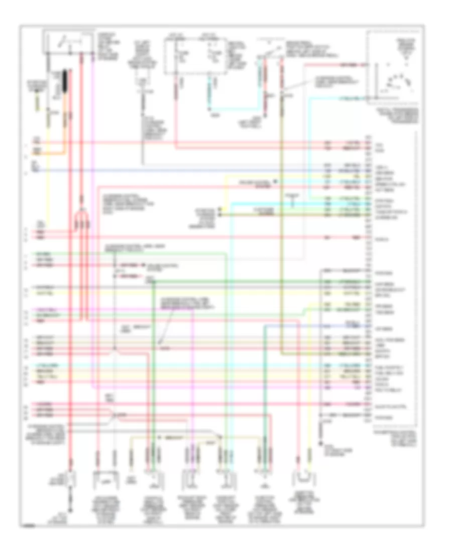
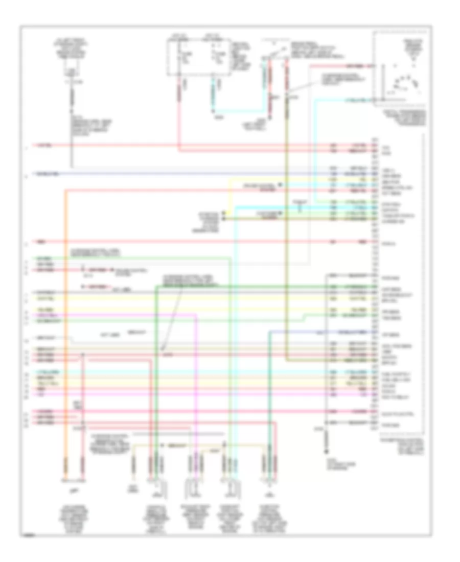
5.4L, Engine Performance Wiring Diagram (4 of 4) for Ford Cab & Chassis F350 Super Duty 2003
List of elements for 5.4L, Engine Performance Wiring Diagram (4 of 4) for Ford Cab & Chassis F350 Super Duty 2003:
- (a/t)
- (calif)
- (engine control harn, near breakout for g101)
- (in engine control harn, near breakout for g101)
- (in engine control sensor & fuel charge harn, near breakout for front of engine compt)
- (in engine control sensor & fuel charge harn, near breakout for right side ex- haust system)
- (in left rear side of engine compt) (california) evap canister vent control solenoid
- (in tail lamps harn, near breakout for c311)
- (not used)
- (on right cylinder head) cylinder head temperature (cht) sensor
- (right side of engine compt) speed control servo
- 5v ref volt
- A/c cltch rly
- A/c system
- A/t
- Anti-lock brakes system
- Bpp sw
- Brake pedal position (bpp) switch (behind left side of dash, above brake pedal)
- C270a
- C270g
- Cam pos in
- Camshaft position (cmp) sensor (on front of left cyl head)
- Canister vent
- Central junction box (behind lower left side of dash)
- Cyl head temp
- Digital transmission range (dtr) sensor (on left side of transmission)
- Dpfe sens
- Epc sol
- From dtr sensor (diagram 1 of 4)
- Fuel inj 1
- Fuel inj 2
- Fuel inj 3
- Fuel inj 4
- Fuel inj 5
- Fuel inj 6
- Fuel inj 7
- Fuel inj 8
- Fuel pump ctrl
- Fuel tank press
- Fuse 10a
- G101 (left side of engine compt)
- G300 (left front footwell)
- Heated oxygen sensor (ho2s) 11 (on right exhaust manifold)
- Heated oxygen sensor (ho2s) 12 (california) (rear of catalytic converter)
- Heated oxygen sensor (ho2s) 21 (on left exhaust manifold)
- Heater ctrl
- Hego 11
- Hego 12
- Hego 21
- Hot at all times
- Iac sol
- Ign coil 2
- Ign coil 4
- Ign coil 7
- Ign coil 8
- Kap b(+)
- Knock sensor
- Knock sensor (on left cyl head)
- M/t
- Maf sens in
- Mass airflow (maf) sensor (in left front of engine compt)
- Nca
- Not used
- Oss
- Powertrain control module (pcm) (on left side of firewall)
- Pwr gnd
- Red
- Red/pnk
- S106
- S114
- S115
- S132
- S134
- S228
- S343
- Sig return
- Tan
- Tan/red
- Tcc sol
- Tp sens in
- Tr3a (a/t)
- Tss
- Vapor valve
- Vpwr
- Vss (+)
- Vss input
6.0L DIESEL
6.0L Diesel, Engine Performance Wiring Diagram (1 of 5) for Ford Cab & Chassis F350 Super Duty 2003
List of elements for 6.0L Diesel, Engine Performance Wiring Diagram (1 of 5) for Ford Cab & Chassis F350 Super Duty 2003:
- (a/t)
- (bap) sens mon
- (in engine control harn, near breakout for c1047)
- (in engine control harn, near breakout for g101)
- (in fog jumper harn, near break- out for c1045)
- (in main harn, near breakout for dlc)
- (in main harn, near breakout to brake pedal support) s224
- (m/t)
- (maf) sens out
- (map) sens mon
- (not used)
- (scp) data -
- (scp) data+
- A/c clutch input
- A/c clutch rly
- A/c system
- A/t
- Abs control module
- Acc
- Apps monitor 1
- Apps monitor 2
- Apps monitor 3
- Apps ref volt 2
- Apps sig rtn 2
- Auxiliary powertrain control module (apcm) (behind left side of dash)
- Auxiliary relay box 5 (at left rear side of engine compt)
- Brake ped pos sw
- Brake pedal position (bpp) switch (behind left side of dash, above brake pedal)
- Brake press sw in
- Brake pressure switch
- C135
- C1381a
- C270h red
- Can bus 1h
- Can bus 1l
- Central junction box (behind lower left side of dash)
- Chassis gnd
- Clutch pedal position (cpp) switch (m/t) (above clutch pedal)
- Computer data lines system
- Cruise control system
- Cust acc tp sig
- Cust acc vss out
- Data link connector (dlc) (behind left side of dash)
- Data output link
- Fuel pmp rly
- Fuel pump monitor
- Fuse 10a
- Fuse 20a
- Fuse 2a
- Fuse 30a
- Fuse 50a
- G100
- G101
- G300 (on vehicle floor, in left front footwell)
- Gen/bat ind
- Grade/load switch (a/t)
- Grd/load sw (cpp) sw
- Hot at all times
- Hot in run
- Injector driver module power relay
- Intk air temp sens
- Lock
- M/t
- Maf sens sig rtn
- Mass airflow (maf) sensor
- Mod prog sig
- Nca
- Off
- Overhead console
- Park brake switch (on park brake assembly)
- Park brk sw input
- Pcm power diode
- Pcm power relay
- Powertrain control module (pcm) (on left fender, near battery)
- Pto ctrl
- Pwr
- Pwr gnd
- Pwr in
- Red
- Ref volt
- Run
- S101
- S106
- S114
- S120 (in engine control harn, near breakout for auxiliary relay box 5)
- S123
- S174
- S217
- S284
- S286
- Sig rtn
- Sig rtn spd ctrl
- Speed ctrl ind
- Speed ctrl sw in
- Start
- Start rly ctrl
- Starting/ charging system
- Starting/charging system
- Tach output
- To fuel pump relay (diagram 2 of 4)
- Vss input
- Water in fuel sens
- Water in fuel sensor (at top right side of engine)
6.0L Diesel, Engine Performance Wiring Diagram (2 of 5) for Ford Cab & Chassis F350 Super Duty 2003
List of elements for 6.0L Diesel, Engine Performance Wiring Diagram (2 of 5) for Ford Cab & Chassis F350 Super Duty 2003:
- (at top front of engine) glow plug control module (gpcm)
- (in engine con-
- (in engine control harn, near breakout for left rear side of engine compt)
- (in main harn, near breakout
- Accelerator pedal position sensor (on accelerator pedal support)
- Barometric absolute pressure (bap) sensor (behind left side of dash)
- C1273a
- C1273b
- C220c
- C270a
- C270f
- Central junction box (behind lower left side of dash)
- Ctrl set lamp
- For c212) s223
- From pcm a power relay (diagram 1 of 4)
- Fuel heater
- Fuel heater relay
- Fuel pump (near left side of trans- mission)
- Fuel pump relay
- Fuse 10a
- Fuse 20a
- Fuse 30a
- G100
- Glow plugs
- Glw plg 1
- Glw plg 2
- Glw plg 3
- Glw plg 4
- Glw plg 5
- Glw plg 6
- Glw plg 7
- Glw plg 8
- Hot at all times
- Hot in run or start
- Inertia fuel shut off switch (behind right side of dash)
- Instrument cluster
- Left valve cover assembly
- Manifold absolute pressure (map) sensor (at right side of firewall)
- Nca
- Pcm
- Power in
- Red
- Right valve cover assembly
- S147
- S162
- S170
- S193
- S213
- S250
- S271
- Speed
- Trol sensor & fuel charge harn, at break- out for top left side of engine)
6.0L Diesel, Engine Performance Wiring Diagram (3 of 5) for Ford Cab & Chassis F350 Super Duty 2003
List of elements for 6.0L Diesel, Engine Performance Wiring Diagram (3 of 5) for Ford Cab & Chassis F350 Super Duty 2003:
- (mounted on rear of left valve cover) injector driver module (idm)
- C1388a
- C1388b
- C270g
- Central junction box (behind lower left side
- Fuel inj 1 gnd
- Fuel inj 1 pwr
- Fuel inj 2 gnd
- Fuel inj 2 pwr
- Fuel inj 3 gnd
- Fuel inj 3 pwr
- Fuel inj 4 gnd
- Fuel inj 4 pwr
- Fuel inj 5 gnd
- Fuel inj 5 pwr
- Fuel inj 6 gnd
- Fuel inj 6 pwr
- Fuel inj 7 gnd
- Fuel inj 7 pwr
- Fuel inj 8 gnd
- Fuel inj 8 pwr
- Fuel injector 1
- Fuel injector 2
- Fuel injector 3
- Fuel injector 4
- Fuel injector 5
- Fuel injector 6
- Fuel injector 7
- Fuel injector 8
- Fuse 10a
- G110 (at top left side of engine)
- Hot at all times
- Nca
- Red red
- S194
6.0L Diesel, Engine Performance Wiring Diagram (4 of 5) for Ford Cab & Chassis F350 Super Duty 2003
List of elements for 6.0L Diesel, Engine Performance Wiring Diagram (4 of 5) for Ford Cab & Chassis F350 Super Duty 2003:
- (a/t)
- (at left side of engine compt) g101
- (epc) sol 1 ctrl
- (epc) sol 2 ctrl
- (epc) sol 3 ctrl
- (epc) sol 4 ctrl
- (epc) sol 5 ctrl
- (epc) sol common
- (idm) pwr rly ctrl
- (in backup light switch to rear light feed harness, in breakout to transmission)
- (in engine control sensor & fuel charge harn, near breakout for left side of engine compt) s196
- (iss) sens in
- (on left fender, near battery)
- (oss) sens in
- (tcc) sol ctrl
- (tcil) ctrl
- (tft) sens
- (tft) sens in
- (tss) sens in
- (w/ elec- tronic shift on the fly)
- Automatic transmission 5r110
- Auxiliary relay box 5 (at left rear side of engine compt)
- C1381b
- C1388c
- Can bus 2h
- Can bus 2l
- Commumincation
- Cylinder id
- Drain wire
- Exterior lights system
- Fuel del com
- Fuse 15a
- Injector driver module (idm) (mounted on rear of left valve cover)
- Line press sol
- Logic pwr
- Neutral sw sen
- Powertrain control module (pcm)
- Pressure control solenoid
- Pressure sw 1 in
- Pressure sw 2 in
- Pressure sw 3 in
- Pressure sw 4 in
- Pressure sw 5 in
- Pwr gnd
- Pwr in
- Red
- Red red
- Ref volt
- Rev lmp rly ctrl
- Rly ctrl bat feed
- S129
- S195
- Sig rtn
- Tran range sens
- Transmission fluid temperature sensor
- Transmission range sensor (trs)
6.0L Diesel, Engine Performance Wiring Diagram (5 of 5) for Ford Cab & Chassis F350 Super Duty 2003
List of elements for 6.0L Diesel, Engine Performance Wiring Diagram (5 of 5) for Ford Cab & Chassis F350 Super Duty 2003:
- (act) sens in
- (ckp) sens +
- (ckp) sens -
- (cmp) sens +
- (cmp) sens -
- (ebp) sens sig
- (eot) sens in
- (icp) sens sig
- (idm) comm
- (idm) cyl id
- (idm) fuel del
- (in engine con- trol sensor & fuel charge harn, at break- out for intake system)
- (in engine control sensor & fuel charge harn, at breakout for left side of engine compt)
- (ipr) ctrl
- (on throttle body) electronic throttle control motor
- (on top of transmission extension housing) output shaft speed (oss) sensor
- Air charge temperature (act) sensor (center front of engine, in intake system)
- C1381c
- C281b
- Camshaft position (cmp) sensor
- Can bus 2h
- Can bus 2l
- Charge monitor
- Cool temp sens
- Cooling fans system
- Crankshaft position (ckp) sensor
- Egr thrtl act
- Egr thrtl pos
- Egr val pos sen
- Egr valve act
- Egr valve actuator (at top of engine)
- Elec fan cltch
- Engine coolant temperature (ect) sensor
- Engine oil temperature (eot) sensor
- Exhaust back pressure sensor
- Fan sig rtn
- Fan spd sig
- Four- wheel drive control module (behind right side of dash)
- Glow plug sys
- Gnd drain wire
- Injection control pressure (icp) sensor
- Injection pressure regulator
- Intermediate shaft
- Nca
- Powertrain control module (pcm) (on left fender, near battery)
- Red
- Ref volt
- S127 (in back-up light switch to rear light feed harn, near breakout for vehicle underbody)
- S128
- S190
- S192
- S197
- Sig rtn
- Speed sensor
- Speed sensor assembly
- Starting/ charging system
- Throttle position (tps) sensor
- Turbine shaft speed sensor
- Turbo vane ctrl
- Variable geometric turbo actuator
6.8L
6.8L, Engine Performance Wiring Diagram (1 of 4) for Ford Cab & Chassis F350 Super Duty 2003
List of elements for 6.8L, Engine Performance Wiring Diagram (1 of 4) for Ford Cab & Chassis F350 Super Duty 2003:
- (at left rear side of engine compt)
- (in engine control sensor & fuel charge harn, near breakout for right cylinder head)
- (in left front footwell)
- (in main harn, near breakout for data link connector)
- (on rear of right cyl head) ignition transformer capacitor 2
- A/c press sw
- A/c system
- Acc
- Anti-theft system
- C270a
- Case gnd
- Ccs
- Central junction box (behind lower left side of dash)
- Ckp(+)
- Ckp(-)
- Coil on plug
- Cust acc 1
- Customer access
- Data link (+)
- Data link (-)
- Data link connector (dlc) (behind left side of dash)
- Data output
- Digital transmission range (dtr) sensor (on left side of transmission)
- Egr sol
- Eprom pwr
- Fuel inj 10
- Fuel pump mon
- Fuse 10a
- Fuse 20a
- Fuse 30a
- G100
- G101 (left side of eng compt)
- G300
- Hego 12
- Hot at all times
- Hot in run or start
- Iat
- Ign coil 1
- Ign coil 10
- Ign coil 5
- Ign coil 6
- Ignition transformer capacitor 1
- Knock sensor
- Lock
- Maf
- Nca
- Not used
- O/d off ind
- Off
- Overdrive cancel switch (a/t)
- Overhead console
- Pcm power diode
- Pcm power relay
- Powertrain control module (pcm) (on left side of firewall)
- Pwr gnd
- R n
- Red
- Run
- S106
- S130 (in engine control sensor & fuel charge harn, near breakout for left cylinder head)
- S135
- S162
- S172
- S258
- S271
- S284
- S286
- Shift sol 1
- Shift sol 2
- Start
- Tcs
- Tft
- To dtr sensor (diagram 4 of 4)
- To fuel pump relay (diagram 2 of 4)
- Tr1
- Tr2
- Tr4
- Trans ctrl ind
- Transmission control switch
- Vss (-)
6.8L, Engine Performance Wiring Diagram (2 of 4) for Ford Cab & Chassis F350 Super Duty 2003
List of elements for 6.8L, Engine Performance Wiring Diagram (2 of 4) for Ford Cab & Chassis F350 Super Duty 2003:
- (at vehicle under body, chassis left side member) g400
- (behind right kick panel) inertia fuel shut-off switch
- (in engine control harn, near breakout for left side of engine compt)
- (part of fuel tank assembly) fuel tank unit
- C2207
- C270a
- C270f
- C270h
- C282
- C4033
- C433
- California
- Central junction box (behind lower left side of dash)
- Crankshaft position (ckp) sensor (on lower front center of engine)
- Crankshaft position sensor shield
- Except pickup
- Federal
- From pcm power relay (diagram 1 of 4)
- Fuel pump relay
- Fuel tank unit (california) (at fuel tank)
- Fuse 20a
- G101 (at left side of engine compt)
- Hot at all times
- Instrument cluster system
- Nca
- Pickup
- Red
- Red/pnk
- S123
- S145
- S161
- S167
- S170 (california) (in engine control harn, near break- out for left rear side of engine compt)
- S401
- Throttle position (tp) sensor (on throttle body)
6.8L, Engine Performance Wiring Diagram (3 of 4) for Ford Cab & Chassis F350 Super Duty 2003
List of elements for 6.8L, Engine Performance Wiring Diagram (3 of 4) for Ford Cab & Chassis F350 Super Duty 2003:
- (in back-up light switch to rear light feed harn, near breakout for left side of transmission)
- (in engine control harn, near breakout for g100)
- (on right rear of engine compt)
- A/c system
- A/t
- Automatic transmission control module (on left side of transmission)
- Coast clutch solenoid
- Electronic pressure controller
- Fuel injectors
- Idle air control (iac) valve (on throttle body assembly)
- M/t
- Output shaft speed (oss) sensor (on top of transmission extension housing)
- Red
- Red/pnk
- S122
- S131 (in engine control sensor & fuel charge harn, near breakout for engine right cylinder head)
- S136 (in engine control sensor & fuel charge harn, near breakout for engine right cylinder head)
- S138
- S139
- Shift solenoid 1
- Shift solenoid 2
- Tan
- Tan/ red
- Tan/red
- Torque converter clutch solenoid
- Transmission fluid temperature sensor
- Turbine shaft speed (tss) sensor (on top of transmission, at converter housing)
- Vapor management valve
6.8L, Engine Performance Wiring Diagram (4 of 4) for Ford Cab & Chassis F350 Super Duty 2003
List of elements for 6.8L, Engine Performance Wiring Diagram (4 of 4) for Ford Cab & Chassis F350 Super Duty 2003:
- (a/t)
- (calif)
- (engine harn, near breakout at left side of engine compt, near brake pressure switch)
- (in engine control harn, near break- out for g101)
- (in engine control harn, near breakout for g101)
- (in engine control sensor & fuel charge harn, near breakout for front of engine compt)
- (in left rear side of engine compt) (california) evap canister vent control solenoid
- (in tail lamps harn, near breakout for c311)
- (on right cylinder head) cylinder head temperature (cht) sensor
- (on right exhaust manifold)
- (right side of engine compt) speed control servo
- 5v ref volt
- A/c cltch rly
- A/c system
- A/t
- Anti-lock brakes system
- Bpp sw
- Brake pedal position (bpp) switch (behind left side of dash, above brake pedal)
- C270a
- C270g
- Cam pos in
- Camshaft position (cmp) sensor (on front of left cyl head)
- Canister vent
- Central junction box (behind lower left side of dash)
- Cyl head temp
- Digital transmission range (dtr) sensor (on left side of transmission)
- Dpfe sens
- Epc sol
- Evap purge
- From dtr sensor (diagram 1 of 4)
- Fuel inj 1
- Fuel inj 2
- Fuel inj 3
- Fuel inj 4
- Fuel inj 5
- Fuel inj 6
- Fuel inj 8
- Fuel inj 9
- Fuel pump ctrl
- Fuel tank press
- Fuse 10a
- G101 (left side of engine compt)
- G300 (in left front footwell)
- Heated oxygen sensor (ho2s) 11
- Heated oxygen sensor (ho2s) 12 (california) (rear of catalytic converter)
- Heated oxygen sensor (ho2s) 21 (on left exhaust manifold)
- Heater ctrl
- Hego 11
- Hego 12
- Hego 21
- Hot at all times
- Iac sol
- Ign coil 3
- Ign coil 4
- Ign coil 7
- Ign coil 8
- Ign coil 9
- Kap b(+)
- Knock sensor
- Knock sensor (on left cyl head)
- M/t
- Maf sens in
- Mass airflow (maf) sensor (in left front of engine compt)
- Nca
- Not used
- Oss
- Powertrain control module (pcm) (on left side of firewall)
- Pwr gnd
- Red
- Red/pnk
- S106
- S114
- S115
- S132
- S134
- S228
- S343
- Side ex- haust system)
- Sig return
- Tan
- Tan/red
- Tcc sol
- Tp sens in
- Tr3a (a/t) cpp (m/t)
- Tss
- Vpwr
- Vss (+)
- Vss input
7.3L DI TURBO DIESEL
7.3L DI Turbo Diesel, Engine Performance Wiring Diagram, California (1 of 4) for Ford Cab & Chassis F350 Super Duty 2003
List of elements for 7.3L DI Turbo Diesel, Engine Performance Wiring Diagram, California (1 of 4) for Ford Cab & Chassis F350 Super Duty 2003:
- (a/t)
- (behind left side of dash)
- (in engine control harn, near break- out for c144)
- (in engine control harn, near break- out for g100) s123
- (in main harn, near breakout for data link connector)
- (m/t)
- (not used)
- A/c head press
- A/c system
- Acc
- Auxiliary powertrain control module (apcm) (pickup) (behind left side of dash)
- Brake press sw
- Brake pressure switch (on left side of engine compt)
- Brake warning
- Bus (+)
- Bus (-)
- Cam pos sens
- Ccs sol
- Central junction box (behind lower left side of dash)
- Cpp (m/t)
- Customer access
- Dash)
- Data link connector (dlc)
- Data output link
- Diesel fuel pump motor (below vehicle, near fuel tank)
- Digital transmission range (dtr) sensor (on left side of transmission)
- Dsl elect drv
- Dtr-tr1
- Dtr-tr2
- Dtr-tr4
- Ebp sens
- Eot
- Epr
- Excursion
- Exhaust pressure regulator (epr) (on top center of engine)
- Fuel htr
- Fuel pump pwr
- Fuse 20a
- Fuse 30a
- G100 (at left rear side of engine compt)
- G100 (left rear side of engine compt)
- G101 (left side of engine compt)
- Gen pwr sw
- Gen scan tool in
- Gpcm
- Hot at all times
- Iat
- Idle validation
- Ignition switch
- Inertia fuel shutoff (ifs) switch (behind right side of dash)
- Injector driver module power relay
- Lock
- Low current sens
- Nca
- Not used
- Off
- Overhead console system
- Passive anti- theft system transceiver module (excursion) (behind left center of dash)
- Pcm power diode
- Pcm power relay
- Pickup
- Powertrain control module (pcm) (on left side of firewall)
- Pwr gnd
- R n
- Red
- Run
- S106
- S141
- S154
- S162
- S217
- S250
- S258
- S260 (in main harn, near break- out for c264)
- S284
- S286
- Speed ctrl ind
- Speed/tach gnd
- Ss1
- Ss2
- Start
- Starting/charging system (w/ dual generators)
- Tcil
- Tcs (a/t)
- Tft
- To dtr sensor (diagram 4 of 4)
- To fuel pump relay (diagram 2 of 4)
- Tp sens
- Wastegate control solenoid (at top rear of engine compt)
- Water in fuel sensor (at top right side of engine)
- Wcs sol
7.3L DI Turbo Diesel, Engine Performance Wiring Diagram, California (2 of 4) for Ford Cab & Chassis F350 Super Duty 2003
List of elements for 7.3L DI Turbo Diesel, Engine Performance Wiring Diagram, California (2 of 4) for Ford Cab & Chassis F350 Super Duty 2003:
- (at top front of engine) glow plug control module (gpcm)
- A/t
- C1273a
- C1273b
- C270a
- C270f
- Central junction box (behind lower left side of dash)
- Clutch pedal position (cpp) switch (m/t) (above clutch pedal)
- Cntl out
- Engine coolant temperature (ect) sensor (on front of engine)
- From pcm a power relay (diagram 1 of 4)
- Fuel pump relay
- Fuse 10a
- Fuse 20a
- Glow plugs
- Glw plg 1
- Glw plg 2
- Glw plg 3
- Glw plg 4
- Glw plg 5
- Glw plg 6
- Glw plg 7
- Glw plg 8
- Gpcm
- Hot at all times
- Hot in run or start
- Instrument cluster
- Instrument cluster system
- M/t
- Nca
- O/d off ind
- Overdrive cancel switch
- Park brake switch (on park brake assembly)
- Power in
- Red
- S126
- S147
- S271
- S278 (in main harn, at breakout for instru- ment cluster)
- Speed control set lamp c220c
- Tcs
7.3L DI Turbo Diesel, Engine Performance Wiring Diagram, California (3 of 4) for Ford Cab & Chassis F350 Super Duty 2003
List of elements for 7.3L DI Turbo Diesel, Engine Performance Wiring Diagram, California (3 of 4) for Ford Cab & Chassis F350 Super Duty 2003:
- (in back-up light switch to rear feed harn, near breakout for left side of transmission)
- (in left side of engine compt) injector driver module (idm)
- Accelerator pedal position sensor (on accelerator pedal support)
- Automatic transmission module
- Cid sig in
- Coast clutch solenoid
- Electronic pressure control solenoid
- Engine oil temperature (eot) sensor (on top front of engine)
- Feedback
- Fuel inj 1
- Fuel inj 2
- Fuel inj 3
- Fuel inj 4
- Fuel inj 5
- Fuel inj 6
- Fuel inj 7
- Fuel inj 8
- Fuel injectors
- Fuel sig
- G101 (left side of engine compt)
- Inj feed
- Intake air temperature sensor (left side of engine compt, behind air cleaner)
- Nca
- Output shaft speed (oss) sensor (on top of transmission extension housing)
- Pwr gnd
- Pwr in
- Red
- S138
- S139
- Shield
- Shift solenoid
- Sig rtn
- Tan
- Tan/red
- Torque converter clutch solenoid
- Transmission fluid temperature sensor
- Turbine shaft speed (tss) sensor (on top of transmission, at converter housing)
7.3L DI Turbo Diesel, Engine Performance Wiring Diagram, California (4 of 4) for Ford Cab & Chassis F350 Super Duty 2003
List of elements for 7.3L DI Turbo Diesel, Engine Performance Wiring Diagram, California (4 of 4) for Ford Cab & Chassis F350 Super Duty 2003:
- (at left side of engine compt) anti-lock brake system (abs) module
- (in engine control harn, near breakout for g101)
- (in engine control harn, near breakout for left rear side of engine compt)
- (in engine control sensor & fuel charge harn, near breakout for rear of engine compt)
- (in engine control sensor & fuel charge harn, near breakout for right side of engine) s1001
- (not used)
- Accl pos sens
- Act sens
- Air charge temperature (act) sensor (center front of engine, in intake system)
- Air intake heater
- Bpp sw
- Brake pedal position (bpp) switch (behind left side of dash, above brake pedal)
- C270a
- C270g
- Camshaft position (cmp) sensor (on lower front center of engine)
- Central junction box (behind lower left side of dash)
- Charge ind
- Cid sig
- Cmp rtn
- Cruise control system
- Customer access
- Digital transmission range (dtr) sensor (on left side of transmission)
- Dtr-tr3a
- Epc sol
- Exhaust back pressure (ebp) sensor (on right rear of engine)
- From dtr sensor (diagram 1 of 4)
- Fuel deliv sig
- Fuel pump rly
- Fuse 10a
- G102 (at right side of engine)
- G111 (at top of engine
- G300 (left front footwell)
- Gen pwr
- Glow plug ctrl
- Hot at all times
- Icp sens
- Idm enable out
- Injection control pressure (icp) sensor (on top left side of engine, right of alternator)
- Injection pressure (ipr) regulator (on top center of engine)
- Ipr sens
- Manifold absolute pressure (map) sensor (on right side of firewall)
- Manifold intake air heater relay (at top right side of engine)
- Map sens
- Oss sens
- Pcm to relay
- Pickup
- Powertrain control module (pcm) (on left side of firewall)
- Pwr
- Pwr gnd
- Pwr in
- Red
- S106
- S114
- S115 (in engine control harn, near breakout for g101)
- S151
- S153
- S170
- S228
- Sig rtn
- Speed ctrl sw
- Starting/ charging system
- Starting/ charging system (w/ dual generators)
- Take off pwr in
- Tcc
- Tss sens
- Vref
- Vss (+)
- Vss out
7.3L DI Turbo Diesel, Engine Performance Wiring Diagram, Federal (1 of 4) for Ford Cab & Chassis F350 Super Duty 2003
List of elements for 7.3L DI Turbo Diesel, Engine Performance Wiring Diagram, Federal (1 of 4) for Ford Cab & Chassis F350 Super Duty 2003:
- (a/t)
- (behind center of dash)
- (in engine control harn, near break- out for c144)
- (in engine control harn, near break- out for g100) s123
- (in main harn, near breakout for data link connector)
- (m/t)
- A/c head press
- A/c system
- Acc
- Auxiliary powertrain control module (apcm) (pickup) (behind left side of dash)
- Brake press sw
- Brake pressure switch (on left side of engine compt)
- Brake warning
- Bus (+)
- Bus (-)
- Cam pos sens
- Ccs sol
- Central junction box (behind lower left side of dash)
- Cpp (m/t)
- Customer access
- Dash)
- Data link connector (dlc)
- Data output link
- Diesel fuel pump motor (below vehicle, near fuel tank)
- Digital transmission range (dtr) sensor (on left side of transmission)
- Dsl elect drv
- Dtr-tr1
- Dtr-tr2
- Dtr-tr4
- Ebp sens
- Eot
- Epr
- Excursion
- Exhaust pressure regulator (epr) (on top center of engine)
- Fuel htr
- Fuel pump pwr
- Fuse 20a
- Fuse 30a
- G100 (at left rear side of engine compt)
- G100 (left rear side of engine compt)
- G101 (left side of engine compt)
- Gen pwr sw
- Gen scan tool in
- Glow plug mon
- Hot at all times
- Iat
- Idle validation
- Ignition switch
- Inertia fuel shutoff (ifs) switch (behind right side of dash)
- Injector driver module power relay
- Lock
- Low current sens
- Nca
- Not used
- Off
- Overhead console system
- Passive anti- theft system transceiver module (excursion) (behind left center of dash)
- Pcm power diode
- Pcm power relay
- Pickup
- Powertrain control module (pcm) (on left side of firewall)
- Pwr gnd
- R n
- Red
- Run
- S106
- S141
- S154
- S162
- S217
- S250
- S258
- S284
- S286
- Speed ctrl ind
- Speed/tach gnd
- Ss1
- Ss2
- Start
- Starting/charging system (w/ dual generators)
- Tcil
- Tcs (a/t)
- Tft
- To dtr sensor (diagram 4 of 4)
- To fuel pump relay (diagram 2 of 4)
- Tp sens
- Wastegate control solenoid (at top rear of engine compt)
- Water in fuel sensor (at top right side of engine)
- Wcs sol
7.3L DI Turbo Diesel, Engine Performance Wiring Diagram, Federal (2 of 4) for Ford Cab & Chassis F350 Super Duty 2003
List of elements for 7.3L DI Turbo Diesel, Engine Performance Wiring Diagram, Federal (2 of 4) for Ford Cab & Chassis F350 Super Duty 2003:
- (in engine control sensor & fuel charge harn, near breakout for right side of engine) s1001
- A/t
- C1279
- C1280
- C270a
- C270f
- Central junction box (behind lower left side of dash)
- Clutch pedal position (cpp) switch (m/t) (above clutch pedal)
- Engine coolant temperature (ect) sensor (on front of engine)
- From pcm a power relay (diagram 1 of 4)
- Fuel pump relay
- Fuse 10a
- Fuse 20a
- G111 (at top of engine)
- Glow plug relay (at top of engine)
- Glow plugs
- Hot at all times
- Hot in run or start
- Injector pressure sensor (on top center of engine)
- Instrument cluster
- Instrument cluster system
- M/t
- Manifold intake air heater 58 amp
- Manifold intake air heater relay (at top right side of engine)
- Nca
- O/d off ind
- Overdrive cancel switch
- Park brake switch (on park brake assembly)
- Red
- S126
- S150
- S271
- S278 (in main harn, at breakout for instru- ment cluster)
- Speed control set lamp c270c
- Tcs
7.3L DI Turbo Diesel, Engine Performance Wiring Diagram, Federal (3 of 4) for Ford Cab & Chassis F350 Super Duty 2003
List of elements for 7.3L DI Turbo Diesel, Engine Performance Wiring Diagram, Federal (3 of 4) for Ford Cab & Chassis F350 Super Duty 2003:
- (in back-up light switch to rear feed harn, near breakout for left side of transmission)
- (in left side of engine compt) injector driver module (idm)
- Accelerator pedal position sensor (on accelerator pedal support)
- Automatic transmission module
- Cid sig in
- Coast clutch solenoid
- Electronic pressure control solenoid
- Engine oil temperature (eot) sensor (on top front of engine)
- Feedback
- Fuel inj 1
- Fuel inj 2
- Fuel inj 3
- Fuel inj 4
- Fuel inj 5
- Fuel inj 6
- Fuel inj 7
- Fuel inj 8
- Fuel injectors
- Fuel sig
- G101 (left side of engine compt)
- Inj feed
- Intake air temperature sensor (left side of engine compt, behind air cleaner)
- Nca
- Output shaft speed (oss) sensor (on top of transmission extension housing)
- Pwr gnd
- Pwr in
- Red
- S138
- S139
- Shield
- Shift solenoid
- Sig rtn
- Tan
- Tan/red
- Torque converter clutch solenoid
- Transmission fluid temperature sensor
- Turbine shaft speed (tss) sensor (on top of transmission, at converter housing)
7.3L DI Turbo Diesel, Engine Performance Wiring Diagram, Federal (4 of 4) for Ford Cab & Chassis F350 Super Duty 2003
List of elements for 7.3L DI Turbo Diesel, Engine Performance Wiring Diagram, Federal (4 of 4) for Ford Cab & Chassis F350 Super Duty 2003:
- (in engine control harn, near breakout for g101)
- (in engine control harn, near breakout for left rear side of engine compt)
- (in engine control sensor & fuel charge harn, near breakout for rear of engine compt)
- (in left front of engine compt) anti-lock brake system (abs) module
- (not used)
- Accl pos sens
- Act sens
- Air charge temperature (act) sensor (center front of engine, in intake system)
- Bpp sw
- Brake pedal position (bpp) switch (behind left side of dash, above brake pedal)
- C135
- C270a
- C270g
- Camshaft position (cmp) sensor (on lower front center of engine)
- Central junction box (behind lower left side of dash)
- Charge ind
- Cid sig
- Cmp rtn
- Cruise control system
- Customer access
- Digital transmission range (dtr) sensor (on left side of transmission)
- Dtr-tr3a
- Epc sol
- Exhaust back pressure (ebp) sensor (on right rear of engine)
- From dtr sensor (diagram 1 of 4)
- Fuel deliv sig
- Fuel pump rly
- Fuse 10a
- G102 (at right side of engine)
- G300 (left front footwell)
- Gen pwr
- Glow plug ctrl
- Hot at all times
- Icp sens
- Idm enable out
- Injection control pressure (icp) sensor (on top left side of engine, right of alternator)
- Ipr sens
- Manifold absolute pressure (map) sensor (on right side of firewall)
- Map sens
- Not used
- Oss sens
- Pcm to relay
- Pickup
- Powertrain control module (pcm) (on left side of firewall)
- Pwr
- Pwr gnd
- Pwr in
- Red
- S106
- S114
- S115 (engine harn, near breakout at left side of steering column)
- S151
- S153
- S170
- S228
- Sig rtn
- Speed ctrl sw
- Starting/ charging system (w/ dual generators)
- Take off pwr in
- Tcc
- Tss sens
- Vref
- Vss (+)
- Vss out

 Čeština
 Dansk
Dansk Deutsch
 Ελληνικά
 English
 English
 Suomi
Suomi Français
 Français
 עברית
עברית Hrvatski
 Magyar
 Italiano
 日本語
日本語 한국어
한국어 Nederlands
 Polski
 Português
 Português
 Română
 Русский
 Slovenčina
 Slovenščina
 Svenska
 Türkçe
 中文 (中国)