ENGINE PERFORMANCE
4.9L
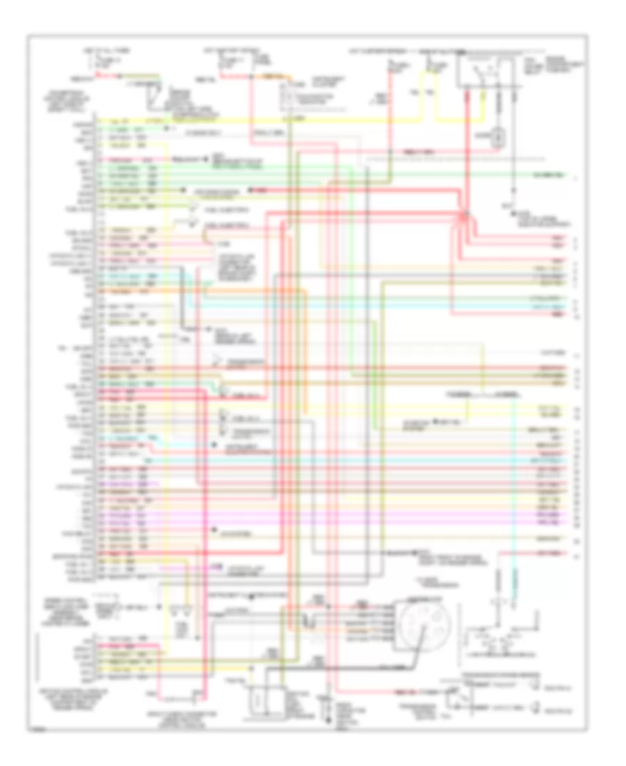
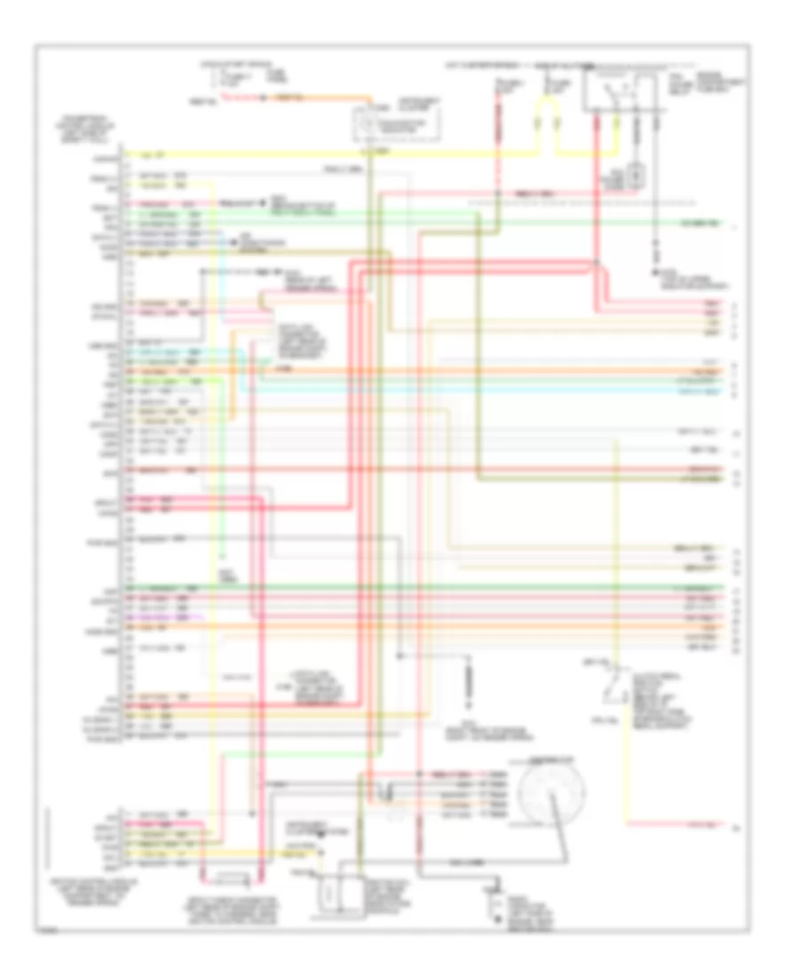
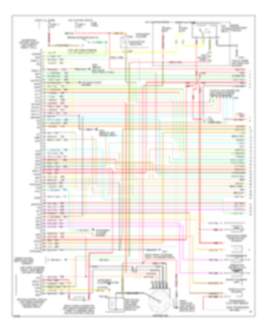
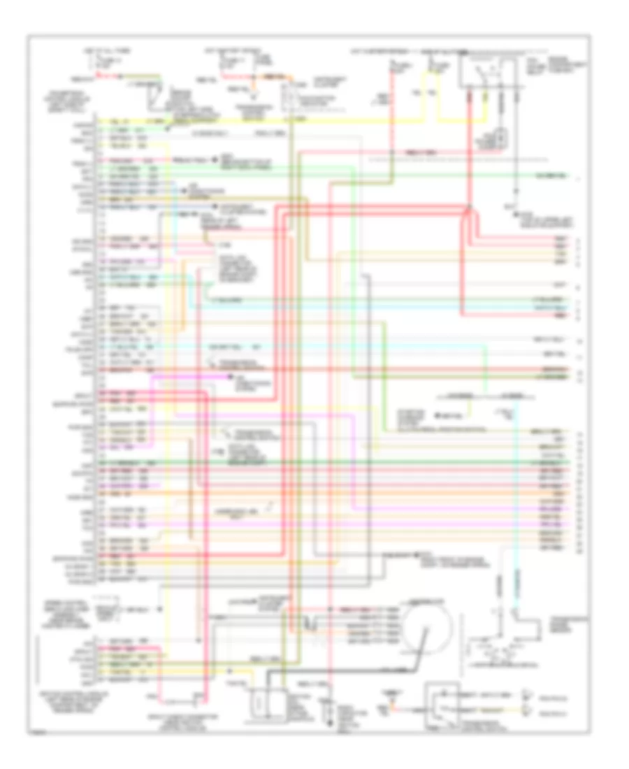
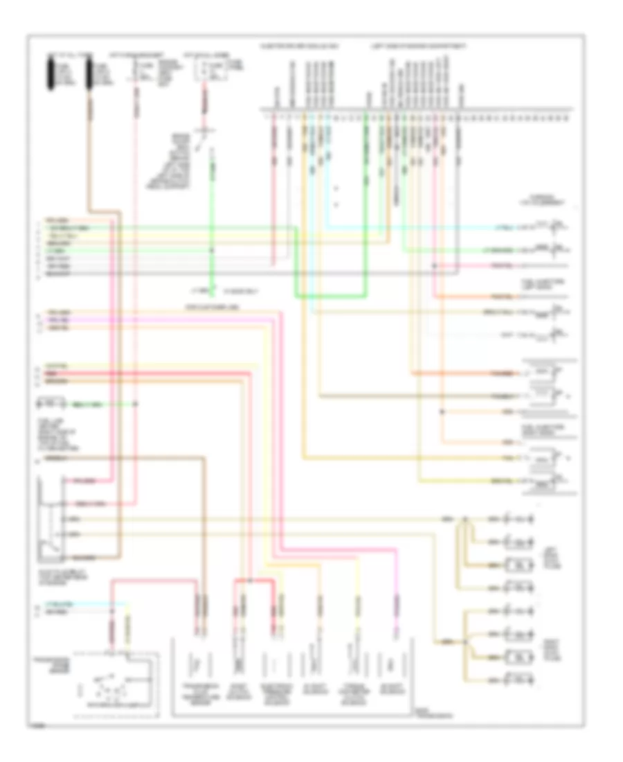
4.9L, Engine Performance Wiring Diagrams, California (1 of 2) for Ford F-Super Duty 1995
List of elements for 4.9L, Engine Performance Wiring Diagrams, California (1 of 2) for Ford F-Super Duty 1995:
- (199)
- * w/ e40d
- 4x4l
- A/c system
- Accs
- Air conditioning (a/c) system
- Airb
- Aird
- Boo
- Brake on/off switch (top left side of brake/clutch pedal support)
- C198
- C199
- C250
- C251
- Ccs
- Ckp
- Coil
- Coil wire
- Cse gnd
- Diode
- Distributor
- Ect
- Engine compartment fuse box
- Epc
- Epcpwr/vpwr
- Evap
- Evp
- Evr
- Fpm
- Fuel inj 1
- Fuel inj 2
- Fuel inj 3
- Fuel inj 4
- Fuel inj 5
- Fuel inj 6
- Fuel injector 5
- Fuel injector 6
- Fuel injs. 2 & 1
- Fuse 13 15a
- Fuse 17 10a
- Fuse i 20a
- Fuse panel
- Fuse u 20a
- G101 (right front of engine compt, on fender apron)
- G104 (rear of left fender apron)
- G108 (top of upper radiator support)
- G203 (behind bottom of right cowl panel)
- Gnd
- H02s (r)
- Ho2s (f)
- Hot at all times
- Hot in start or run
- Iac
- Iat
- Idm
- Ign gnd
- Ignition coil (left front of engine)
- Ignition control module (left rear of engine compartment on fender apron)
- Instrument cluster
- Instrument cluster system
- Kapwr
- Maf
- Malfunction indicator
- Nca
- Or cpp
- Pcm pin 32
- Pcm pin 41
- Pcm power relay
- Pip
- Pnk
- Powertrain control module (left side of safety wall)
- Pwr
- Pwr gnd
- Radio capacitor (near ignition coil)
- Red
- Sig rtn
- Speed control servo amplifier assembly (near brake master cylinder)
- Spout
- Spout check connector (near ignition control module)
- Ss1
- Ss2
- Start
- Starting system
- Sto/mil
- Tan
- Tcc
- Tcil
- Tcs
- Tft
- Tr *
- Transmission
- Transmission control switch
- Transmission range sensor
- Transmission switch
- Vehicle speed input
- Vip data link
- Vip data link (+)
- Vip data link (-)
- Vip data link connector
- Vip data link connector (left rear of engine compt, on bracket)
- Vpwr
- Vref
- Vss (+)
- Vss (-)
- W/ e4od
- W/ e4od only
- W/o e4od
- Wac relay
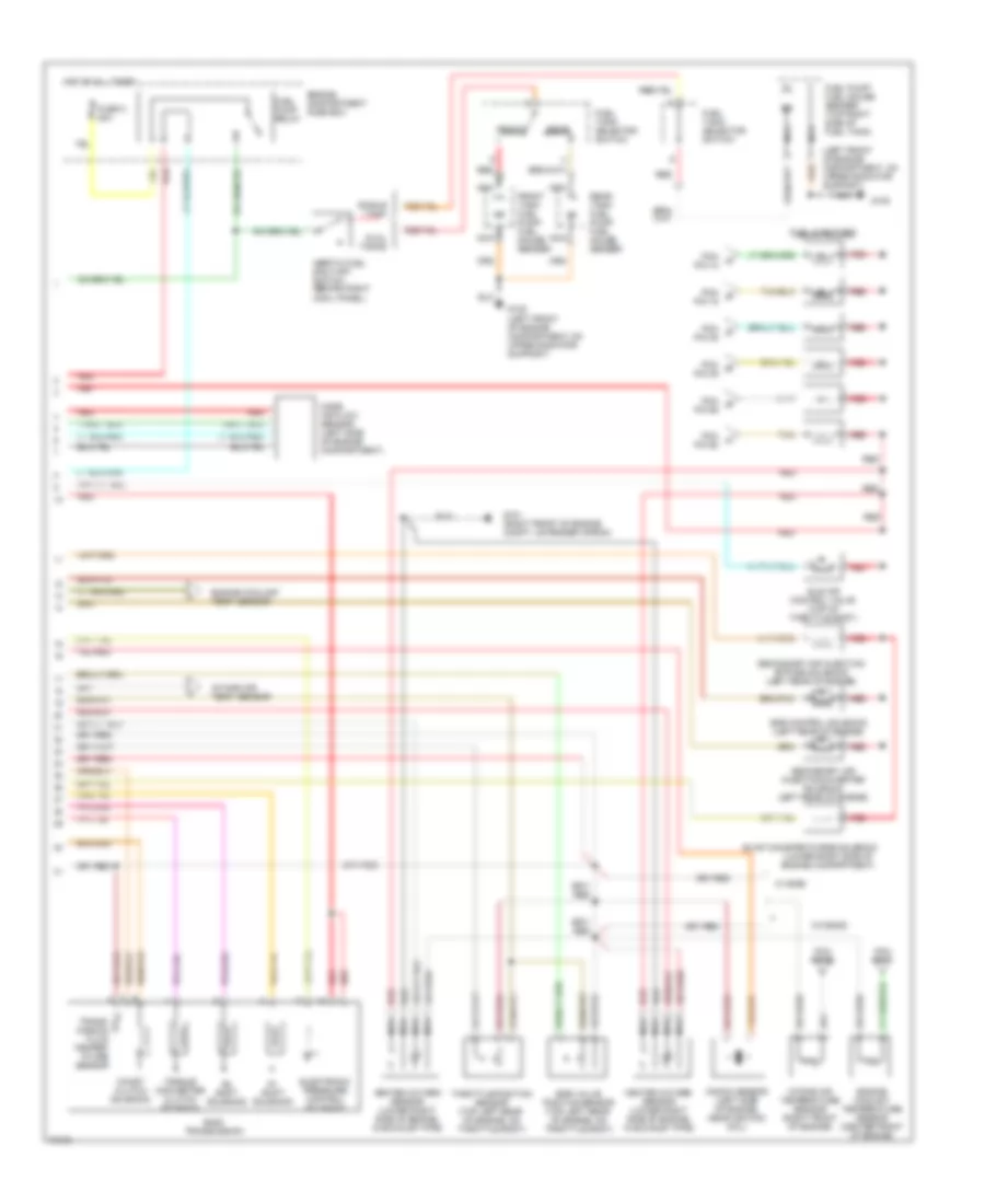
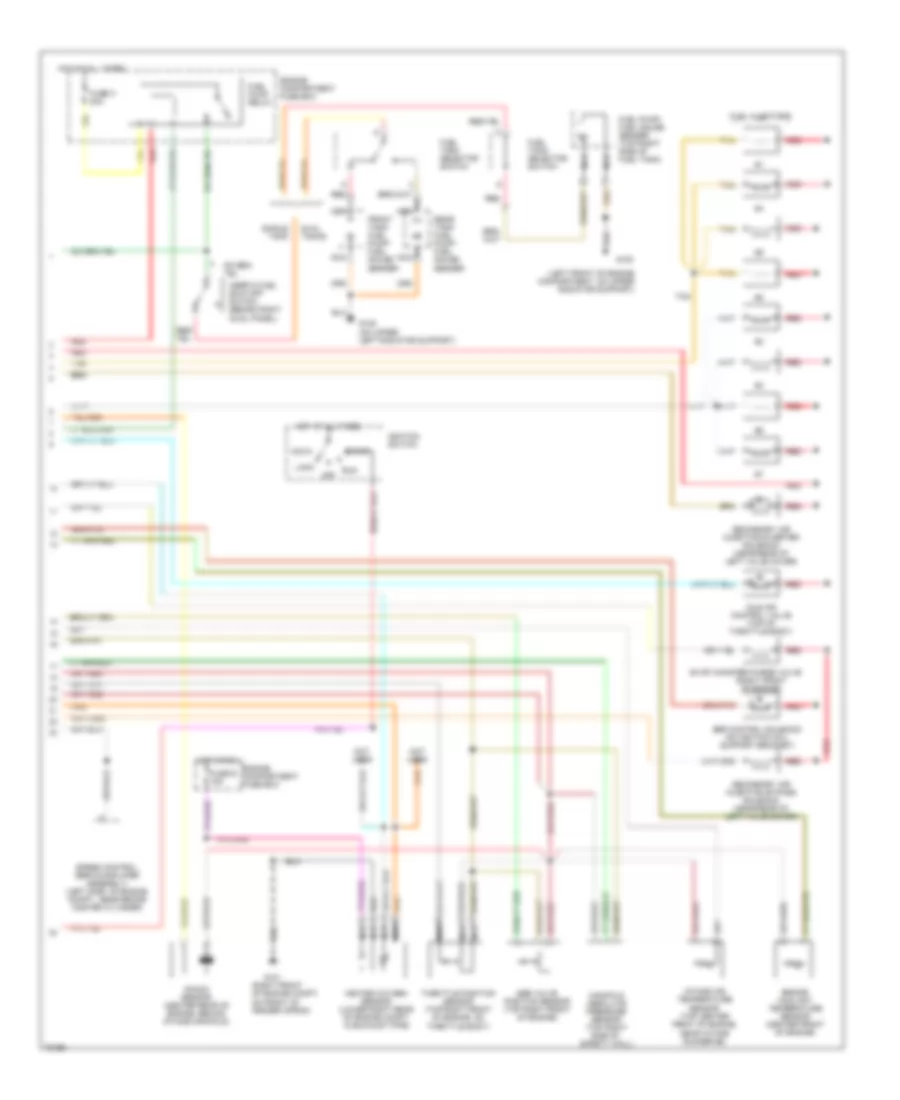
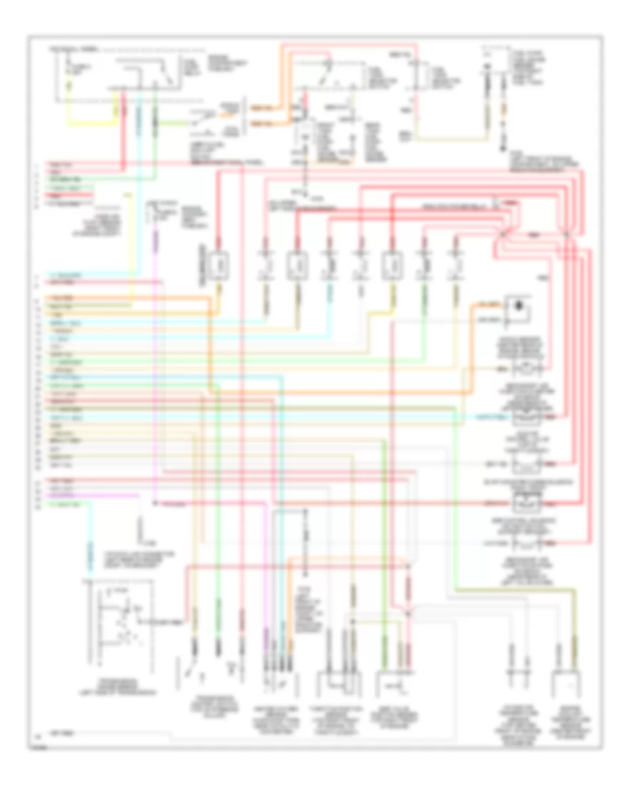
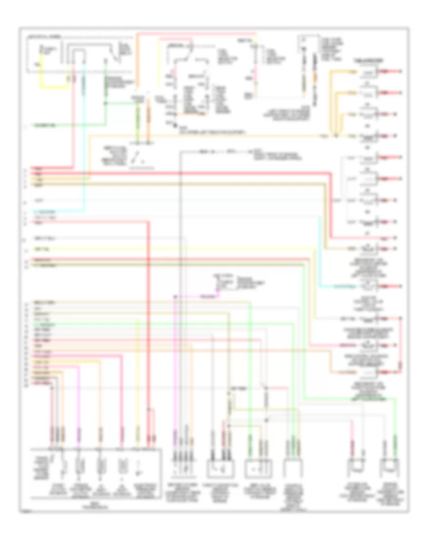
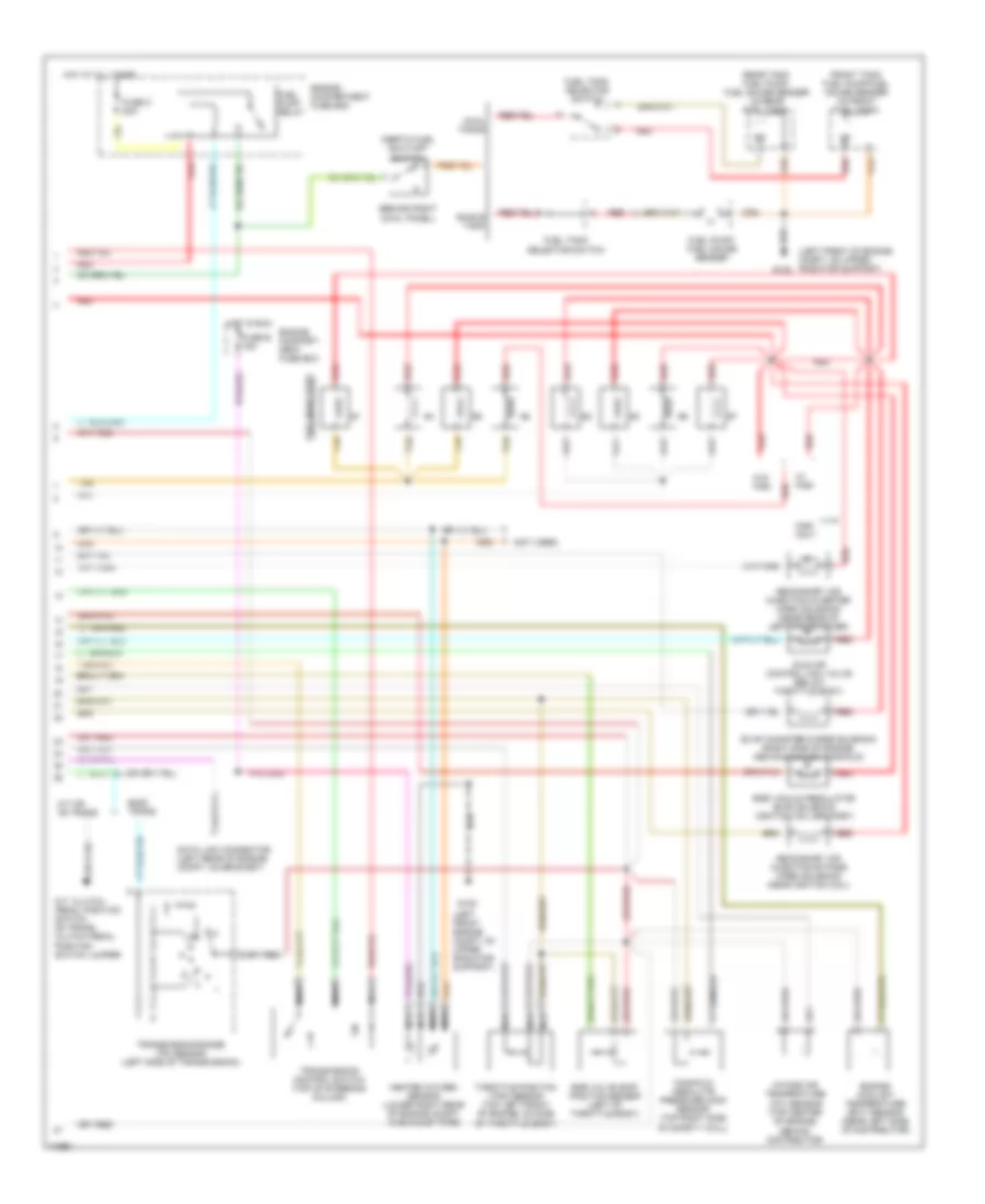
4.9L, Engine Performance Wiring Diagrams, California (2 of 2) for Ford F-Super Duty 1995
List of elements for 4.9L, Engine Performance Wiring Diagrams, California (2 of 2) for Ford F-Super Duty 1995:
- #1 shift solenoid
- #2 shift solenoid
- (left front of engine compartment, on upper radiator support)
- (lower right side of engine compartment)
- Coast clutch solenoid
- Dual tanks
- E40d transmission
- Egr control solenoid (left rear of engine)
- Egr valve position sensor (top left rear of engine, on throttle body)
- Electronic pressure control solenoid
- Engine compartment fuse box
- Engine coolant temp. sensor
- Engine coolant temperature sensor (center front of engine)
- Evap canister purge solenoid
- Front
- Front tank fuel pump/ fuel gauge sender
- Fuel injectors
- Fuel pump relay
- Fuel pump/ fuel gauge sender (top right side of fuel tank)
- Fuel tank selector switch
- Fuse o 20a
- G101 (right front of engine compt, on fender apron)
- G108
- Heated oxygen sensor (lower right side of engine, in exhaust pipe)
- Hot at all times
- Idle air control valve (top of throttle body)
- Inertia fuel shut-off switch (behind right cowl panel)
- Intake air temp. sensor
- Intake air temperature sensor (right front of engine)
- Knock sensor (left side of engine, near ignition coil)
- Mass air flow sensor (left side of engine compartment)
- Nca
- Pcm a
- Pcm b
- Pcm d
- Pcm e
- Pcm g
- Pcm h
- Pcm pin 25
- Pcm pin 7
- Pin 12
- Pin 15
- Pin 35
- Pin 39
- Pin 58
- Pin 59
- Rear
- Rear tank fuel pump/ fuel gauge sender
- Red
- Secondary air injection bypass solenoid (left rear of engine)
- Secondary air injection diverter solenoid (left rear of engine)
- Single tank
- Tan
- Throttle position sensor (top left rear of engine, on throttle body)
- Torque converter clutch solenoid
- Trans- mission fluid temper- ature sensor
- W/ e40d
- W/o e40d
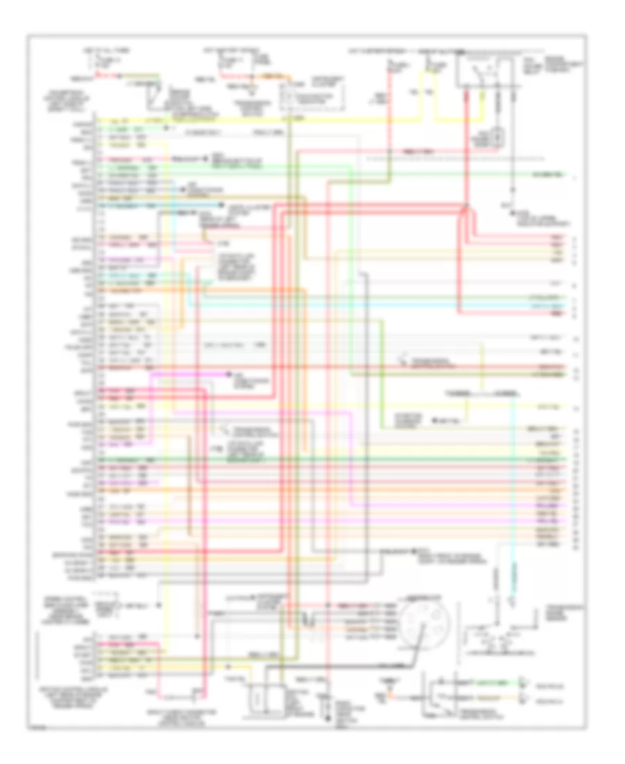
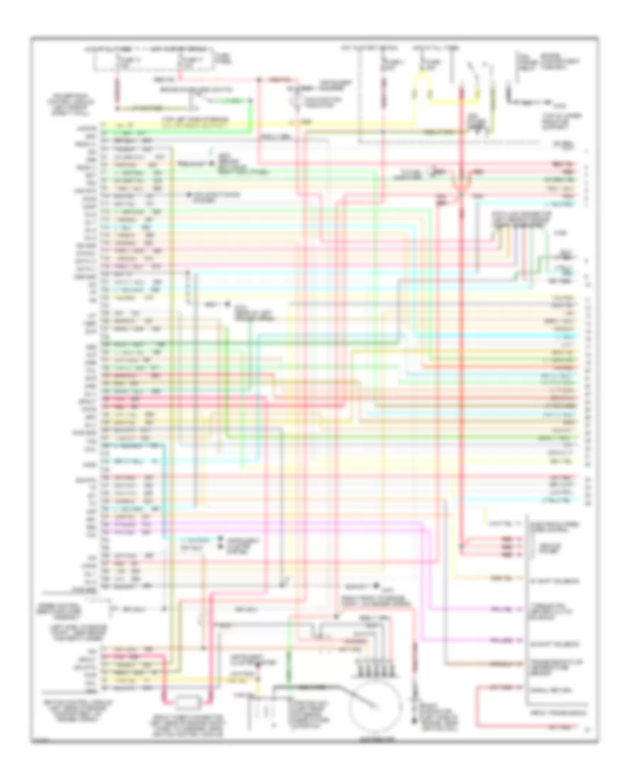
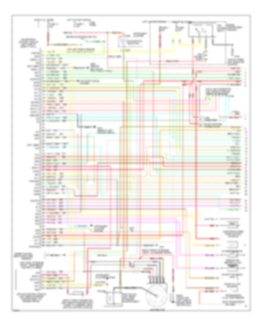
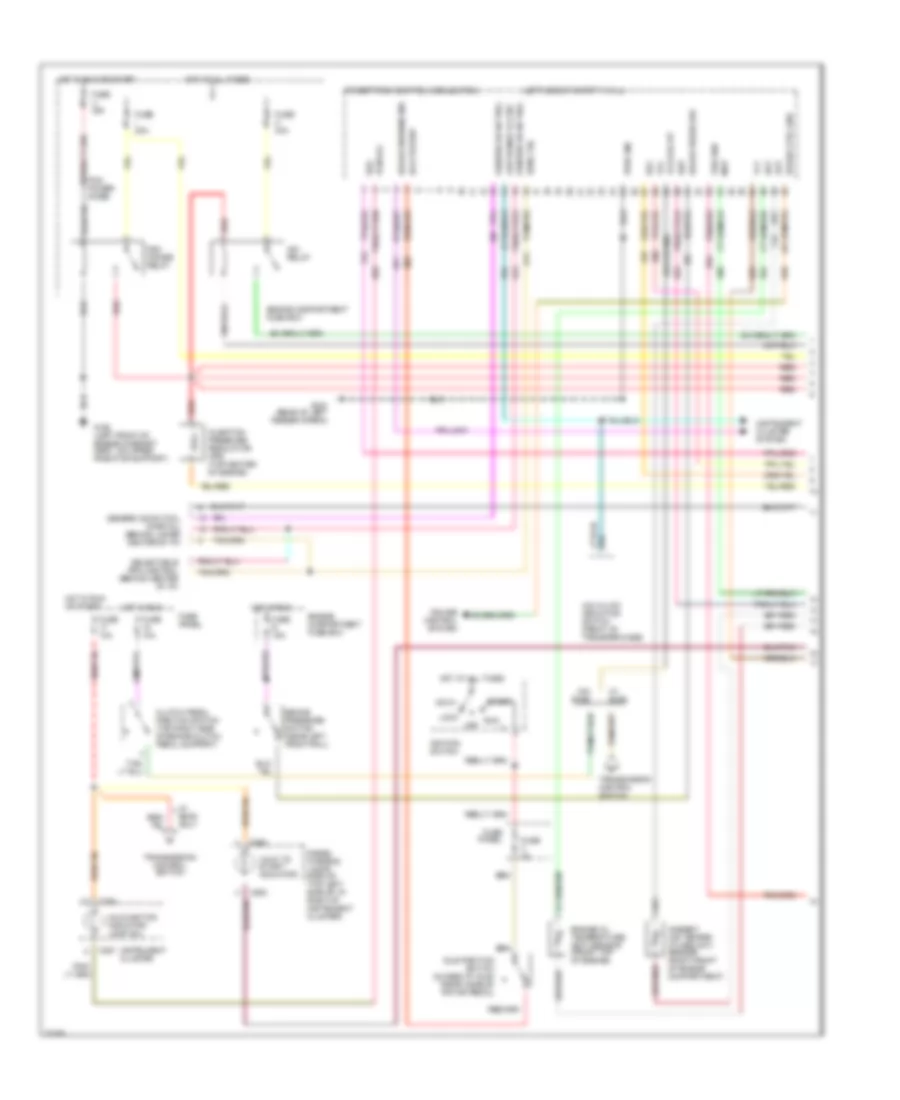
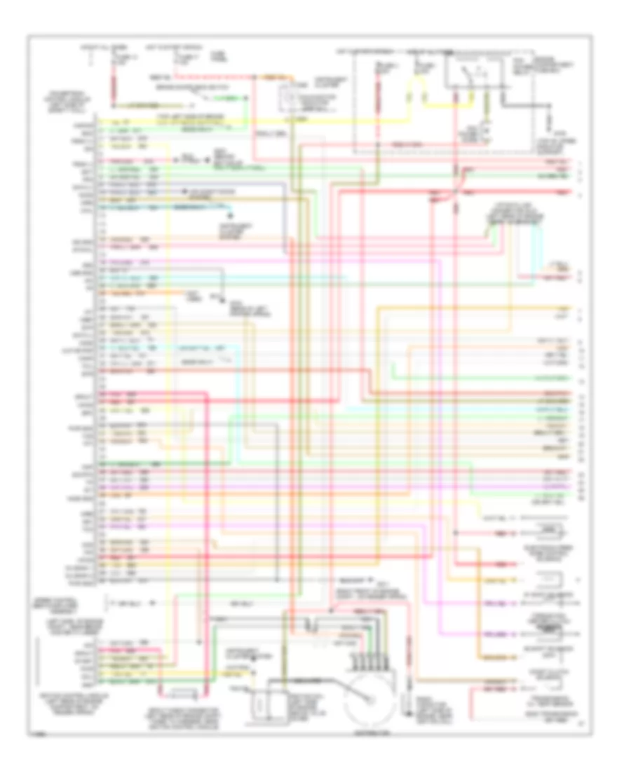
4.9L, Engine Performance Wiring Diagrams, Except California (1 of 2) for Ford F-Super Duty 1995
List of elements for 4.9L, Engine Performance Wiring Diagrams, Except California (1 of 2) for Ford F-Super Duty 1995:
- (199)
- 4 x 4l
- Accs
- Acd
- Air conditioning system
- Airb
- Aird
- Boo
- Brake on/off switch (top left side of brake/clutch pedal support)
- C198
- C199
- C250
- C251
- Canp
- Ccs
- Coil
- Coil wire
- Cse gnd
- Data (+)
- Data (-)
- Distributor
- Ect
- Engine compartment fuse box
- Epc
- Epcpwr/vpwr
- Evp
- Evr
- Fpm
- Fuse 13 15a
- Fuse 17
- Fuse 17 10a
- Fuse i 20a
- Fuse panel
- Fuse u 20a
- G101 (right front of engine compt, on fender apron)
- G104 (rear of left fender apron)
- G108 (top of upper radiator support)
- G203 (behind bottom of right cowl panel)
- Gnd
- Ho2s
- Ho2s gnd
- Hot at all times
- Hot in start or run
- Iac
- Iat
- Idm
- Ign gnd
- Ignition coil (left front of engine)
- Ignition control module (left rear of engine compartment on fender apron)
- Inj bank 1
- Inj bank 2
- Instr. cluster system
- Instrument cluster
- Instrument cluster system
- Kapwr
- Malfunction indicator
- Map
- Nca
- Pcm pin 32
- Pcm pin 41
- Pcm power diode
- Pcm power relay
- Pip
- Pnk
- Powertrain control module (left side of safety wall)
- Psom (+)
- Psom (-)
- Pwr
- Pwr gnd
- Radio capacitor (near ignition coil)
- Red
- Sig rtn
- Speed control servo/amplifier assembly (near brake master cylinder)
- Spout
- Spout check connector (near ignition control module)
- Ss1
- Ss2
- Start
- Starting/ charging system
- Sti
- Sto/mil
- Tan
- Tcc
- Tcil
- Tcs
- Tft
- Tr or cpp
- Transmission control switch
- Transmission range sensor
- Vehicle speed input
- Vip data link connector (left rear of engine compt)
- Vip data link connector (left rear of engine compt, on bracket)
- Vpwr
- Vref
- W/ e4od
- W/ e4od only
- W/o e4od
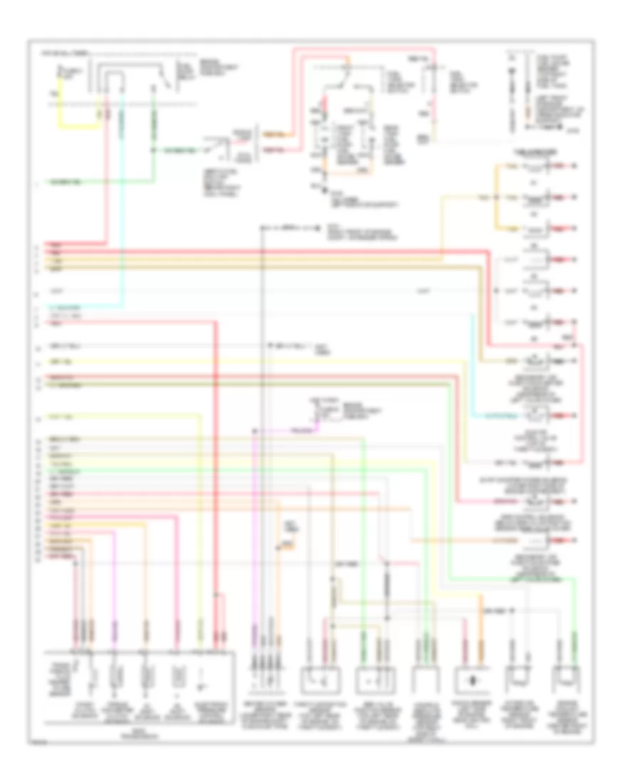
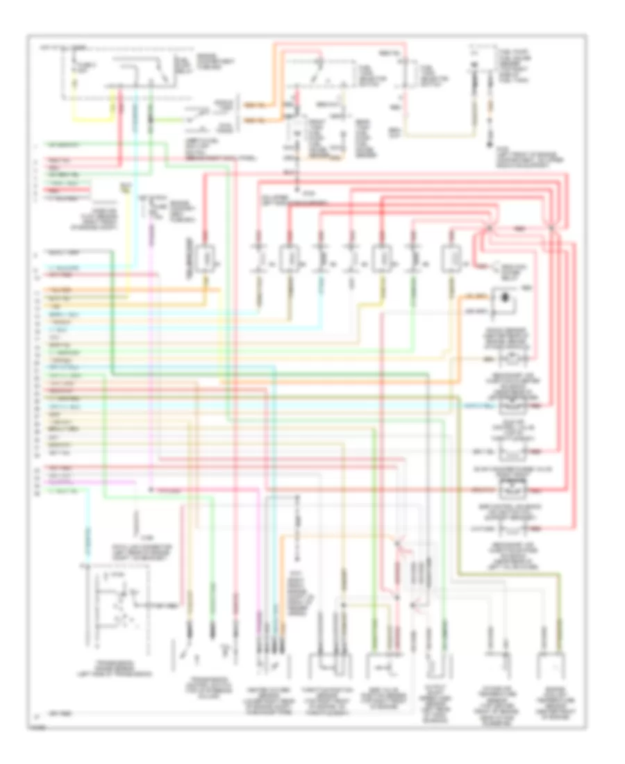
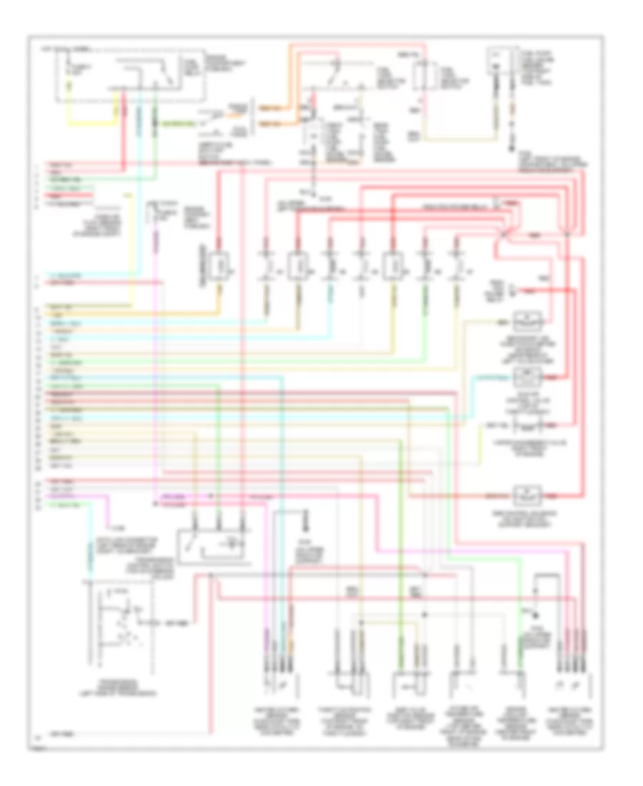
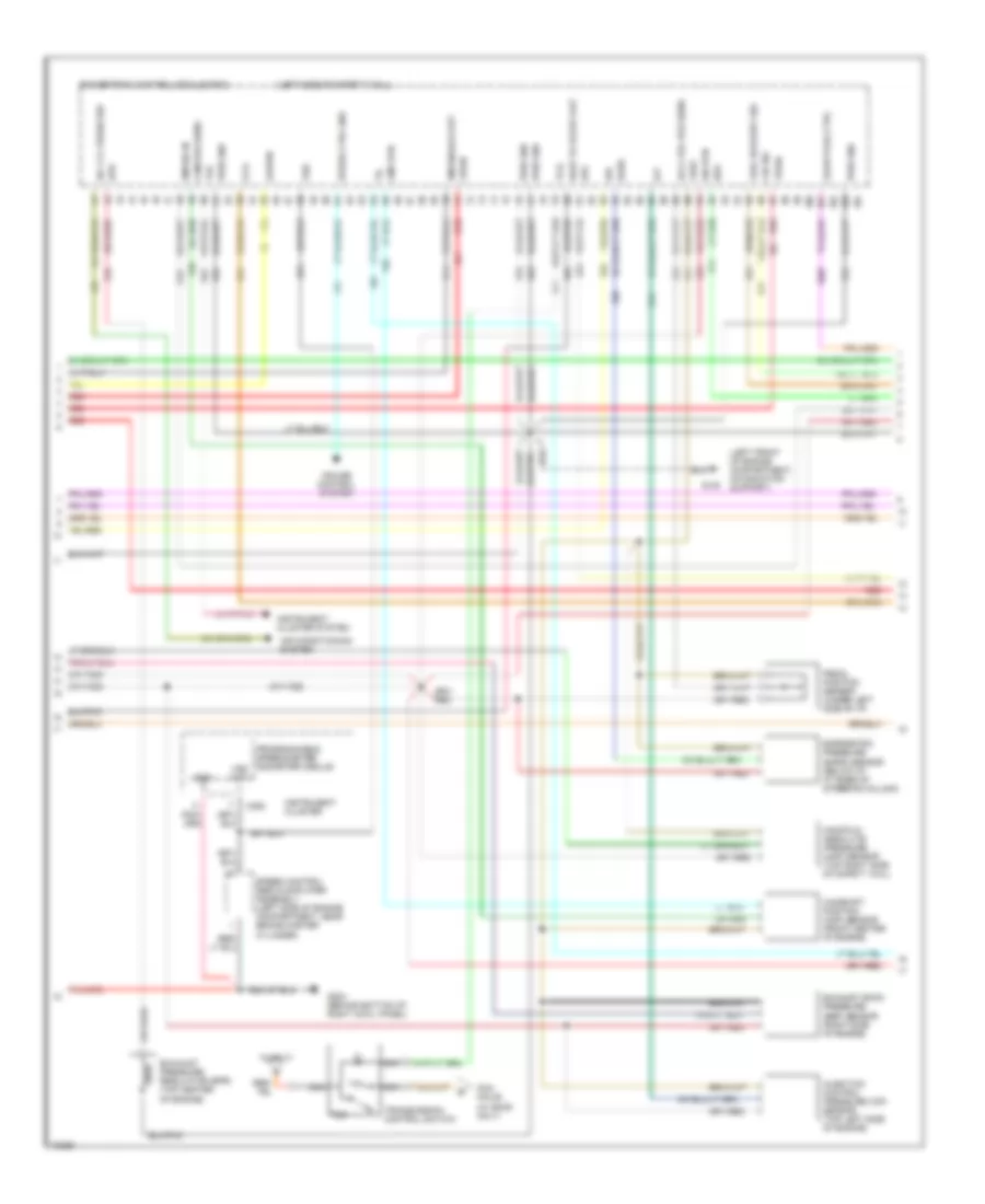
4.9L, Engine Performance Wiring Diagrams, Except California (2 of 2) for Ford F-Super Duty 1995
List of elements for 4.9L, Engine Performance Wiring Diagrams, Except California (2 of 2) for Ford F-Super Duty 1995:
- #1 shift solenoid
- #2 shift solenoid
- (left front of engine compartment, on upper radiator support)
- (lower right side of engine compartment)
- (not used)
- (on upper left radiator support)
- Coast clutch solenoid
- Dual tanks
- E40d transmission
- Egr control solenoid (below egr valve position sensor near valve cover)
- Egr valve position sensor (top left rear of engine, on throttle body)
- Electronic pressure control solenoid
- Engine compartment fuse box
- Engine coolant temperature sensor (center front of engine)
- Evap canister purge solenoid
- Front tank fuel pump/ fuel gauge sender
- Fuel injectors
- Fuel pump relay
- Fuel pump/ fuel gauge sender (top right side of fuel tank)
- Fuel tank selector switch
- Fuse e 15a
- Fuse o 20a
- G101 (right front of engine compt, on fender apron)
- G108
- Heated oxygen sensor (lower right rear of engine compt, in exhaust pipe)
- Hot at all times
- Hot in run
- Idle air control valve (top of throttle body)
- Inertia fuel shut-off switch (behind right cowl panel)
- Intake air temperature sensor (right front of engine)
- Knock sensor (left side of engine, near ignition coil)
- Manifold absolute pressure sensor (top right side of safety wall)
- Nca
- Rear tank fuel pump/ fuel gauge sender
- Red
- Secondary air injection bypass solenoid (near rear of left valve cover)
- Secondary air injection diverter solenoid (near rear of left valve cover)
- Single tank
- Tan
- Throttle position sensor (top left rear of engine, on throttle body)
- Torque converter clutch solenoid
- Trans- mission fluid temper- ature sensor
5.0L
5.0L MFI, Engine Performance Wiring Diagrams (1 of 2) for Ford F-Super Duty 1995
List of elements for 5.0L MFI, Engine Performance Wiring Diagrams (1 of 2) for Ford F-Super Duty 1995:
- (not used)
- (right front of engine compt, on fender apron)
- Accs
- Air conditioning system
- Airb
- Aird
- C198
- C250
- C251
- Canp
- Clutch pedal position switch (behind left side of i/p, top right side of brake/clutch pedal support)
- Coil
- Coil wire
- Cpp
- Cse gnd
- Data (+)
- Data (-)
- Data link connector (left rear of engine compt, on bracket)
- Data link connector c199 (left rear of engine compt, on bracket)
- Distributor
- Ect
- Engine compartment fuse box
- Evp
- Evr
- Fpm
- Fuse 17 10a
- Fuse i 20a
- Fuse panel
- Fuse u 20a
- G101
- G104 (rear of left fender apron)
- G108 (top of upper radiator support)
- G203 (behind bottom of right cowl panel)
- Gnd
- Ho2s
- Ho2s gnd
- Hot at all times
- Hot in start or run
- Iac
- Iat
- Idm
- Ign gnd
- Ignition coil (left rear of engine, near intake manifold)
- Ignition control module (left rear of engine compartment, on fender apron)
- Inj bank 1
- Inj bank 2
- Instrument cluster
- Instrument clusters system
- Kapwr
- Malfunction indicator
- Map
- Nca
- Pcm power diode
- Pcm power relay
- Pip
- Pnk
- Powertrain control module (left side of safety wall)
- Psom (+)
- Psom (-)
- Psp
- Pwr
- Pwr gnd
- Radio capacitor (left side of engine, near ignition coil)
- Red
- Sig rtn
- Spout
- Spout check connector (left rear of engine compt, taped to harness, near ignition control module)
- Start
- Sti
- Sto/mil
- Tan
- Vpwr
- Vref
5.0L MFI, Engine Performance Wiring Diagrams (2 of 2) for Ford F-Super Duty 1995
List of elements for 5.0L MFI, Engine Performance Wiring Diagrams (2 of 2) for Ford F-Super Duty 1995:
- (left front of engine compartment, on upper radiator support)
- (on upper left radiator support)
- (right front of engine compt, on front of fender apron)
- (right front of engine)
- Acc
- Dual tanks
- Egr control solenoid (on ignition coil support bracket)
- Egr valve position sensor (top right front of engine)
- Engine compartment fuse box
- Engine coolant temperature sensor (center front of engine)
- Evap canister purge valve
- Front tank fuel pump/ fuel gauge sender
- Fuel injectors
- Fuel pump relay
- Fuel pump/ fuel gauge sender (top right side of fuel tank)
- Fuel tank selector switch
- Fuse e 15a
- Fuse o 20a
- G101
- G108
- Heated oxygen sensor (lower right rear of engine compt, in exhaust pipe)
- Hot at all times
- Hot in run
- Idle air control valve (top of throttle body)
- Ignition switch
- Inertia fuel shut-off switch (behind right cowl panel)
- Intake air temperature sensor (top center front of engine, near intake runner #6)
- Knock sensor (center rear of engine, behind intake manifold)
- Lock
- Manifold absolute pressure sensor (top right side of safety wall)
- Nca
- Not used
- Off
- Rear tank fuel pump/ fuel gauge sender
- Red
- Run
- Secondary air injection bypass solenoid (near rear of left valve cover)
- Secondary air injection diverter solenoid (near rear of left valve cover)
- Single tank
- Speed control servo/amplifier assembly) (left side of engine compt., near brake master cylinder)
- Start
- Tan
- Throttle position sensor (top right front of engine, on throttle body)
5.0L SFI, Engine Performance Wiring Diagrams, with 4R70W Transmission (1 of 2) for Ford F-Super Duty 1995
List of elements for 5.0L SFI, Engine Performance Wiring Diagrams, with 4R70W Transmission (1 of 2) for Ford F-Super Duty 1995:
- #1 shift solenoid
- #2 shift solenoid
- (left side of engine compt., near brake master cylinder)
- (right front of engine compt, on fender apron)
- (top left side of brake/ clutch pedal support)
- (top of upper radiator support)
- 4r70w transmission
- 4x4l
- Accs
- Air conditioning system
- Airb
- Aird
- Boo
- Brake on/off (boo) switch
- C198
- C250
- C251
- Canp
- Coil
- Coil wire
- Cse gnd
- Data (+)
- Data (-)
- Data link connector (left rear of engine compt, on bracket)
- Distributor
- Ect
- Electronic pres-
- Engine compartment fuse box
- Epc
- Evp
- Evr
- Fpm
- Fuse 13 15a
- Fuse 17 10a
- Fuse i 20a
- Fuse panel
- Fuse u 20a
- G101
- G104 (rear of left fender apron)
- G108
- G203 (behind bottom of right cowl panel)
- Gnd
- Ho2s
- Hot at all times
- Hot in start or run
- Iac
- Iat
- Idm
- Idm (fto)
- Ign gnd
- Ignition coil (left rear of engine, near intake manifold)
- Ignition control module (left rear of engine compartment, on fender apron)
- Inj 1
- Inj 2
- Inj 3
- Inj 4
- Inj 5
- Inj 6
- Inj 7
- Inj 8
- Instrument cluster
- Instrument cluster system
- Kapwr
- Maf
- Maf rtn
- Malfunction indicator
- Mlp
- Nca
- Oss
- Pcm
- Pcm power relay
- Pip
- Pnk
- Power diode
- Powertrain control module (left side of safety wall)
- Psom (+)
- Psom (-)
- Pwr
- Pwr gnd
- Radio capacitor (left side of engine, near ignition coil)
- Red
- Sig rtn
- Signal return
- Solenoid
- Speed control servo/amplifier assembly
- Spout
- Spout check connector (left rear of engine compt, taped to harness, near ignition control module)
- Ss1
- Ss2
- Sti
- Sto/mil
- Sure control
- Tan
- Tan/red
- Tcc
- Tcil
- Tcs
- Tfi
- To fuel injectors
- Torque con- verter clutch
- Transmission fluid temperature sensor
- Vehicle power
- Vpwr
- Vref
5.0L SFI, Engine Performance Wiring Diagrams, with 4R70W Transmission (2 of 2) for Ford F-Super Duty 1995
List of elements for 5.0L SFI, Engine Performance Wiring Diagrams, with 4R70W Transmission (2 of 2) for Ford F-Super Duty 1995:
- (on upper left radiator support)
- (right front engine compt, 0n front of fender apron)
- C199
- Data link connector (left rear of engine compt, on bracket)
- Dual tanks
- Egr control solenoid (on ignition coil support bracket)
- Egr valve position sensor (top right front of engine)
- Engine compart- ment fuse box
- Engine compartment fuse box
- Engine coolant temperature sensor (center front of engine)
- Evap canister purge valve (right front of engine)
- From pcm power relay
- Front tank fuel pump/ fuel gauge sender
- Fuel injectors
- Fuel pump relay
- Fuel pump/ fuel gauge sender (top right side of fuel tank)
- Fuel tank selector switch
- Fuse e 15a
- Fuse o 20a
- G101
- G108
- G108 (left front of engine compartment, on upper radiator support)
- Heated oxygen sensor (lower right rear of engine compt, in exhaust pipe)
- Hot at all times
- Hot in run
- Idle air control valve (top of throttle body)
- Inertia fuel shut-off switch (behind right cowl panel)
- Intake air temperature sensor (top center front of engine, near intake runner #6)
- Knock sensor (center rear of engine, behind intake manifold)
- Mass air flow sensor (right front of engine compt)
- Nca
- Output shaft speed (oss) sensor (left rear of tran- smission)
- Rear tank fuel pump/ fuel gauge sender
- Red
- Secondary air injection bypass solenoid (near rear of left valve cover)
- Secondary air injection diverter solenoid (near rear of left valve cover)
- Single tank
- Tan
- Tan/red
- Tcil
- Throttle position sensor (top right front of engine, on throttle body)
- Transmission control switch (top of steering column)
- Transmission range sensor (left side of transmission)
5.0L SFI, Engine Performance Wiring Diagrams, with E4OD Transmission (1 of 2) for Ford F-Super Duty 1995
List of elements for 5.0L SFI, Engine Performance Wiring Diagrams, with E4OD Transmission (1 of 2) for Ford F-Super Duty 1995:
- #1 shift solenoid
- #2 shift solenoid
- (left side of engine compt., near brake master cylinder)
- (right front of engine compt, on fender apron)
- (top left side of brake/ clutch pedal support)
- (top of upper left radiator support)
- 4x4l
- Accs
- Air conditioning system
- Airb
- Aird
- Boo
- Brake on/off (boo) switch
- C198
- C250
- C251
- Canp
- Ccs
- Coast clutch solenoid
- Coil
- Coil wire
- Cse gnd
- Data (+)
- Data (-)
- Distributor
- E40d transmission
- Ect
- Electronic pres- sure control solenoid
- Engine compartment fuse box
- Epc
- Evp
- Evr
- Fpm
- Fuse 13 15a
- Fuse 17 10a
- Fuse i 20a
- Fuse panel
- Fuse u 20a
- G101
- G104 (rear of left fender apron)
- G108
- G203 (behind bottom of right cowl panel)
- Gnd
- Ho2s
- Hot at all times
- Hot in start or run
- Iac
- Iat
- Idm
- Ign gnd
- Ignition coil (left rear of engine, near intake manifold)
- Ignition control module (left rear of engine compartment, on fender apron)
- Inj 1
- Inj 2
- Inj 3
- Inj 4
- Inj 5
- Inj 6
- Inj 7
- Inj 8
- Instrument cluster
- Instrument cluster system
- Instrument clusters system
- Kapwr
- Maf
- Maf rtn
- Malfunction indicator
- Mlp
- Nca
- Pcm power diode
- Pcm power relay
- Pip
- Pnk
- Powertrain control module (left side of safety wall)
- Psom (+)
- Psom (-)
- Pwr
- Pwr gnd
- Radio capacitor (left side of engine, near ignition coil)
- Red
- Sig rtn
- Speed control servo/amplifier assembly
- Spout
- Spout check connector (left rear of engine compt, taped to harness, near ignition control module)
- Ss1
- Ss2
- Start
- Sti
- Sto/mil
- Tan
- Tan/red
- Tcc
- Tcil
- Tcs
- Tfi
- To fuel injectors
- Torque con- verter clutch solenoid
- Transmission fluid temp sensor
- Vip data link connector (left rear of engine compt, on bracket)
- Vpwr
- Vref
5.0L SFI, Engine Performance Wiring Diagrams, with E4OD Transmission (2 of 2) for Ford F-Super Duty 1995
List of elements for 5.0L SFI, Engine Performance Wiring Diagrams, with E4OD Transmission (2 of 2) for Ford F-Super Duty 1995:
- (left front of engine compt, 0n upper radiator support)
- (on upper left radiator support)
- Dual tanks
- Egr control solenoid (on ignition coil support bracket)
- Egr valve position sensor (top right front of engine)
- Engine compart- ment fuse box
- Engine compartment fuse box
- Engine coolant temperature sensor (center front of engine)
- Evap canister purge solenoid (right front of engine)
- From pcm power relay
- Front tank fuel pump/ fuel gauge sender
- Fuel injectors
- Fuel pump relay
- Fuel pump/ fuel gauge sender (top right side of fuel tank)
- Fuel tank selector switch
- Fuse e 15a
- Fuse o 20a
- G108
- G108 (left front of engine compartment, on upper radiator support)
- Heated oxygen sensor (in exhaust pipe, near catalytic converter)
- Hot at all times
- Hot in run
- Idle air control valve (top of throttle body)
- Inertia fuel shut-off switch (behind right cowl panel)
- Intake air temperature sensor (top center front of engine, near intake runner #6)
- Knock sensor (center rear of engine, behind intake manifold)
- Mass air flow sensor (right front of engine compt)
- Nca
- Rear tank fuel pump/ fuel gauge sender
- Red
- Secondary air injection bypass solenoid (near rear of left valve cover)
- Secondary air injection diverter solenoid (near rear of left valve cover)
- Single tank
- Tan
- Tan/red
- Tcil
- Throttle position sensor (top right front of engine, on throttle body)
- Transmission control switch (top of steering column)
- Transmission range sensor (left side of transmission)
- Vip data link connector (left rear of engine compt, on bracket)
5.8L
5.8L, Engine Performance Wiring Diagrams, California (1 of 2) for Ford F-Super Duty 1995
List of elements for 5.8L, Engine Performance Wiring Diagrams, California (1 of 2) for Ford F-Super Duty 1995:
- #1 shift solenoid
- #2 shift solenoid
- (left side of engine compt., near brake master cylinder)
- (not used)
- (right front of engine compt, on fender apron)
- (top left side of brake/ clutch pedal support)
- (top of upper left radiator support)
- 4x4l
- Accs
- Air conditioning system
- Aird
- Boo
- Brake on/off (boo) switch
- C198
- C250
- C251
- Canp
- Ccs
- Coast clutch solenoid
- Coil
- Coil wire
- Cse gnd
- Data (+)
- Data (-)
- Data link connector (left rear of engine compt, on bracket)
- Distributor
- E40d transmission
- Ect
- Electronic pres- sure control solenoid
- Engine compartment fuse box
- Epc
- Evap canister purge valve
- Evp
- Evr
- Fpm
- Fuel injectors
- Fuse 13 15a
- Fuse 17 10a
- Fuse i 20a
- Fuse panel
- Fuse u 20a
- G101
- G104 (rear of left fender apron)
- G108
- G203 (behind bottom of right cowl panel)
- Gnd
- Ho2s
- Hot at all times
- Hot in start or run
- Iac
- Iat
- Idm
- Idm (fto)
- Ign gnd
- Ignition coil (left rear of engine compartment)
- Ignition control module (left rear of engine compartment, on fender apron)
- Inj 1
- Inj 2
- Inj 3
- Inj 4
- Inj 5
- Inj 6
- Inj 7
- Inj 8
- Instrument cluster
- Instrument cluster system
- Kapwr
- Maf
- Maf rtn
- Malfunction indicator
- Mlp
- Nca
- Pcm power diode
- Pcm power relay
- Pip
- Pnk
- Powertrain control module (left side of safety wall)
- Psom (+)
- Psom (-)
- Pwr
- Pwr gnd
- Radio capacitor (left side of engine, near ignition coil)
- Red
- Sig rtn
- Speed control servo/amplifier assembly
- Spout
- Spout check connector (left rear of engine compt, taped to harness, near ignition control module)
- Ss1
- Ss2
- Sti
- Sto/mil
- Tan
- Tan/red
- Tcc
- Tcil
- Tcs
- Tfi
- Torque con- verter clutch solenoid
- Transmission fluid temp sensor
- Vpwr
- Vref
5.8L, Engine Performance Wiring Diagrams, California (2 of 2) for Ford F-Super Duty 1995
List of elements for 5.8L, Engine Performance Wiring Diagrams, California (2 of 2) for Ford F-Super Duty 1995:
- (on upper left radiator support)
- (on upper radiator support)
- C199
- Data link connector (left rear of engine compt, on bracket)
- Dual tanks
- Egr control solenoid (on ignition coil support bracket)
- Egr valve position sensor (top right front of engine)
- Engine compart- ment fuse box
- Engine compartment fuse box
- Engine coolant temperature sensor (center front of engine)
- From pcm power relay
- Front tank fuel pump/ fuel gauge sender
- Fuel injectors
- Fuel pump relay
- Fuel pump/ fuel gauge sender (top right side of fuel tank)
- Fuel tank selector switch
- Fuse e 15a
- Fuse o 20a
- G108
- G108 (left front of engine compartment, on upper radiator support)
- G108 (on upper radiator support)
- Heated oxygen sensor (in exhaust pipe, near catalytic converter)
- Hot at all times
- Hot in run
- Idle air control valve (top of throttle body)
- Inertia fuel shut-off switch (behind right cowl panel)
- Intake air temperature sensor (top center front of engine, near intake runner #6)
- Mass air flow sensor (right front of engine compt)
- Nca
- Rear tank fuel pump/ fuel gauge sender
- Red
- Secondary air injection diverter solenoid (near rear of left valve cover)
- Single tank
- Tan
- Tan/red
- Tcil
- Throttle position sensor (top right front of engine, on throttle body)
- Transmission control switch (top of steering column)
- Transmission range sensor (left side of transmission)
- Vapor management valve (right front of engine)
5.8L, Engine Performance Wiring Diagrams, Except California (1 of 2) for Ford F-Super Duty 1995
List of elements for 5.8L, Engine Performance Wiring Diagrams, Except California (1 of 2) for Ford F-Super Duty 1995:
- (fto) idm
- 4 x 4l
- Accs
- Acd
- Air conditioning system
- Airb
- Aird
- Boo
- Brake on/off switch (top left side of brake/clutch pedal support)
- C198
- C199
- C250
- C251
- Canp
- Ccs
- Coil
- Coil wire
- Cse gnd
- Data (+)
- Data (-)
- Data link connector (left rear of engine compt)
- Data link connector (left rear of engine compt, on bracket)
- Distributor
- Ecppwr/vpwr
- Ect
- Engine compartment fuse box
- Epc
- Epcpwr/vpwr
- Evp
- Evr
- Fpm
- Fuse 13 15a
- Fuse 17
- Fuse 17 10a
- Fuse i 20a
- Fuse panel
- Fuse u 20a
- G101 (right front of engine compt, on fender apron)
- G104 (rear of left fender apron)
- G108 (top of upper left radiator support)
- G203 (behind bottom of right cowl panel)
- Gnd
- Ho2s
- Ho2s gnd
- Hot at all times
- Hot in start or run
- Iac
- Iat
- Idm
- Ign gnd
- Ignition coil (near intake manifold)
- Ignition control module (left rear of engine compartment, on fender apron)
- Inj bank 1
- Inj bank 2
- Instrument cluster
- Instrument cluster system
- Kapwr
- Malfunction indicator
- Map
- Nca
- Pcm pin 32
- Pcm pin 41
- Pcm power diode
- Pcm power relay
- Pip
- Pnk
- Powertrain control module (left side of safety wall)
- Psom (+)
- Psom (-)
- Pwr
- Pwr gnd
- Radio capacitor (near ignition coil)
- Red
- Sig rtn
- Speed control servo amplifier assembly (near brake master cylinder)
- Spout
- Spout check connector (near ignition control module)
- Ss1
- Ss2
- Starting/ charging system (clutch pedal position switch)
- Sti
- Sto/mil
- Tan
- Tcc
- Tcil
- Tcs
- Tft
- Tr or cpp
- Transmission control switch
- Transmission range sensor
- Under 85oo lbs. only
- Vehicle speed input
- Vref
- W/ e4od
- W/ e4od only
- W/o e4od
5.8L, Engine Performance Wiring Diagrams, Except California (2 of 2) for Ford F-Super Duty 1995
List of elements for 5.8L, Engine Performance Wiring Diagrams, Except California (2 of 2) for Ford F-Super Duty 1995:
- #1 shift solenoid
- #2 shift solenoid
- (on upper left radiator support)
- Canister purge solenoid (lower right side of engine compartment)
- Coast clutch solenoid
- Dual tanks
- E40d transmission
- Egr control solenoid (on ignition coil support bracket)
- Egr valve position sensor (top right front of engine)
- Electronic pressure control solenoid
- Engine compartment fuse box
- Engine coolant temperature sensor (center front of engine)
- Front tank fuel pump/ fuel gauge sender
- Fuel injectors
- Fuel pump relay
- Fuel pump/ fuel gauge sender (top right side of fuel tank)
- Fuel tank selector switch
- Fuse e 15a
- Fuse o 20a
- G101 (right front of engine compt, on fender apron)
- G108
- G108 (left front of engine compartment, on upper radiator support)
- Heated oxygen sensor (lower right rear of engine compt, in exhaust pipe)
- Hot at all times
- Hot in run
- Idle air control valve (top of throttle body)
- Inertia fuel shut-off switch (behind right cowl panel)
- Intake air temperature sensor (top center front of engine)
- Manifold absolute pressure sensor (top right side of safety wall)
- Nca
- Rear tank fuel pump/ fuel gauge sender
- Red
- Secondary air injection bypass solenoid (near rear of left valve cover)
- Secondary air injection diverter solenoid (near rear of left valve cover)
- Single tank
- Tan
- Throttle position sensor (top right front of engine)
- Torque converter clutch solenoid
- Trans- mission fluid temper- ature sensor
7.3L
7.3L DI Turbo Diesel, Engine Performance Wiring Diagrams (1 of 3) for Ford F-Super Duty 1995
List of elements for 7.3L DI Turbo Diesel, Engine Performance Wiring Diagrams (1 of 3) for Ford F-Super Duty 1995:
- "wait to start" indicator
- (224 or 306)
- (left side of safety wall)
- 4x4 hi/low indicator switch (front of transfer case)
- Aat
- Acc
- Ambient air temper- ature (aat) sensor (right front of engine compartment)
- Brake press sw
- Brake pressure switch (near left front rail)
- Brake warning ind
- C250
- C251
- C264
- Clutch pedal position switch (top right side of brake/clutch pedal support)
- Cruise control system
- Diesel warning lamps display (top left side of i/p, right of instrument cluster)
- Ebp
- Engine compartment fuse box
- Engine oil temperature (eot) sensor (front top of engine)
- Eot
- Fuse 10a
- Fuse 3a
- Fuse e 15a
- Fuse h 30a
- Fuse i 20a
- Fuse panel
- Fuse u 30a
- G104 (rear of left fender apron)
- G108 (left front of engine compart- ment, on upper radiator support)
- Generic scan tool
- Generic scan tool (partial) (behind lower center of i/p)
- Hot at all times
- Hot in run
- Hot in run or start
- Idle pos sw
- Idle position switch (closed at idle) (near accele- rator pedal)
- Idm relay
- Ignition switch
- Injection pressure regulator (ipr) (top center of engine)
- Instrument cluster
- Instrument cluster system
- Lock
- Low range 4x4 sw
- Malfunction indicator lamp (mil)
- Map
- Off
- Pcm dlc
- Pcm power relay
- Power diode
- Powertrain control module (pcm)
- Pwr gnd
- Red
- Rpm ctrl
- Run
- Selectable rpm control (behind center of i/p)
- Speed ctrl gnd
- Ss1
- Ss2
- Start
- Tcc
- Tcs or cpp
- Tft
- Transmission control switch
- Vss gnd
- W/ e4od
- W/ e4od only
- W/o e4od
7.3L DI Turbo Diesel, Engine Performance Wiring Diagrams (2 of 3) for Ford F-Super Duty 1995
List of elements for 7.3L DI Turbo Diesel, Engine Performance Wiring Diagrams (2 of 3) for Ford F-Super Duty 1995:
- (left front of engine compartment, on radiator support)
- (left side of safety wall)
- (w/ e4od only)
- A/c cyl press sw
- Accl pdl pos sens
- Air conditioning system
- Baro
- Barometric pressure (baro) sensor (below i/p, at base of steering column)
- Boo
- C252
- Cam pos sens
- Camshaft position (cmp) sensor (front center of engine)
- Ccs
- Cid sig
- Cmp rtn
- Cruise control system
- Epc
- Epr
- Exhaust back pressure (ebp) sensor (right side of engine)
- Exhaust pressure regulator (epr) (top center of engine)
- Fuel delivery sig
- Fuse 17
- G108
- G203 (behind bottom of right cowl panel)
- Glow plug ctrl
- Gnd
- Icp
- Idm enable out
- Idm sig in
- Injection control pressure (icp) sensor (top left side of engine)
- Instrument cluster
- Instrument cluster system
- Ipr
- Kapwr
- Manifold absolute pressure (map) sensor (top right side of safety wall
- Nca
- Pcm pin 29
- Pedal position sensor (under left side of i/p)
- Powertrain control module (pcm)
- Programmable speedometer/ odometer module
- Pwr gnd
- Red
- Sig rtn
- Speed control servo/amplifier assembly (left side of engine compartment, near brake master cylinder)
- Speed ctrl gnd
- Tac
- Tcil
- Tcs
- Transmission control switch
- Vpwr
- Vref
- Vss
- Vss out
- Wait to start out
7.3L DI Turbo Diesel, Engine Performance Wiring Diagrams (3 of 3) for Ford F-Super Duty 1995
List of elements for 7.3L DI Turbo Diesel, Engine Performance Wiring Diagrams (3 of 3) for Ford F-Super Duty 1995:
- #1 shift solenoid
- #2 shift solenoid
- (for customer use)
- (left side of engine compartment)
- Brake on/off (boo) switch (behind left side of i/p, top left side of brake/clutch pedal support)
- Cid sig in
- Coast clutch solenoid
- E4od transmission
- Electronic pressure control solenoid
- Engine compart- ment fuse box
- Fuel delivery sig
- Fuel inj feed left
- Fuel inj feed right
- Fuel injector #1
- Fuel injector #1 fuel injector #8
- Fuel injector #2
- Fuel injector #3
- Fuel injector #4
- Fuel injector #5
- Fuel injector #6
- Fuel injector #7
- Fuel injectors (left bank)
- Fuel injectors (right bank)
- Fuel line heater (right side of engine, on top of fuel filter/heater)
- Fuse 15a
- Fuse panel
- Fuse u 30a
- Glow plug relay (top center rear of engine)
- Hot at all times
- Hot in run or start
- Idm feedback sig
- Inj shield gnd
- Injector driver module (idm)
- Left bank glow plugs
- Nca
- Pwr gnd
- Red
- Right bank glow plugs
- Sig rtn
- Tan
- Tan/red
- Torque converter clutch solenoid
- Transmission fluid temperature sensor
- Transmission range sensor
- Vpwr
- W/ e4od only
- Warning: 115v dc present
7.5L
7.5L, Engine Performance Wiring Diagrams (1 of 2) for Ford F-Super Duty 1995
List of elements for 7.5L, Engine Performance Wiring Diagrams (1 of 2) for Ford F-Super Duty 1995:
- #1 shift solenoid
- #2 shift solenoid
- (e4od only)
- (left rear of engine compt, on bracket)
- (left side of engine compt., near brake master cylinder)
- (not used)
- (right front of engine compt., on fender apron)
- (top left side of brake/ clutch pedal support)
- (top of upper radiator support)
- 4x4l
- Accs
- Air conditioning system
- Airb
- Aird
- Boo
- Brake on/off (boo) switch
- C250
- C251
- Canp
- Ccs
- Coast clutch solenoid
- Coil
- Coil wire
- Connector (dlc)
- Cse gnd
- Data (-)
- Distributor
- E40d transmission
- Ect
- Electronic pres- sure control solenoid
- Engine compartment fuse box
- Epc
- Evp
- Evr
- Fpm
- Fuse 13 15a
- Fuse 17 10a
- Fuse i 20a
- Fuse panel
- Fuse u 20a
- G101
- G104 (rear of left fender apron)
- G108
- G203 (behind bottom of right cowl panel)
- Gnd
- Ho2s
- Ho2s gnd
- Hot at all times
- Hot in start or run
- Iac
- Iat
- Idm
- Ign gnd
- Ignition coil (left side of engine, above valve cover)
- Ignition control module (left rear of engine compartment, on fender apron)
- Inj bank 1
- Inj bank 2
- Instrument cluster
- Instrument cluster system
- Kapwr
- Malfunction indicator lamp (mil)
- Map
- Mlp or pnp
- Nca
- Pcm power diode
- Pcm power relay
- Pip
- Pnk
- Powertrain control module (left side of safety wall)
- Psom (+)
- Psom (-)
- Pwr
- Pwr gnd
- Radio capacitor (left side of engine, near ignition coil)
- Red
- Sig rtn
- Speed control servo/amplifier assembly
- Spout
- Spout check connector (left rear of engine compt, taped to harness, near ignition control module)
- Ss1
- Ss2
- Start
- Sti
- Sto/mil
- Tan
- Tcc
- Tcil
- Tcs
- Tft
- Torque con- verter clutch solenoid
- Transmission oil temp sensor
- Vip data link
- Vpwr
- Vref
7.5L, Engine Performance Wiring Diagrams (2 of 2) for Ford F-Super Duty 1995
List of elements for 7.5L, Engine Performance Wiring Diagrams (2 of 2) for Ford F-Super Duty 1995:
- (behind right cowl panel)
- (left front engine compt, 0n upper radiator support)
- (left front of engine compt, on upper radiator support)
- (not used)
- Data link connector (left rear of engine compt, on bracket)
- Dual tanks
- E40d trans
- Egr vacuum regulator (evr) solenoid (ignition coil bracket)
- Egr valve (evp) position sensor (left of throttle body)
- Engine compart- ment fuse box
- Engine compartment fuse box
- Engine coolant temperature (ect) sensor (near left side of distributor)
- Evap canister purge solenoid (right side of engine, above exhaust manifold)
- F450 only
- Front tank fuel pump/fuel gauge sender (in front fuel tank)
- Fuel injectors
- Fuel pump relay
- Fuel pump/ fuel gauge sender
- Fuel tank selector switch
- Fuse e 15a
- Fuse o 20a
- G108
- Heated oxygen sensor (lower right rear of engine compt, in exhaust pipe)
- Hot at all times
- Hot in run
- Idle air control (iac) valve (below throttle body)
- Inertia fuel shut-off switch
- Intake air temperature (iat) sensor (top center of engine, behind distributor)
- M/t or c6 trans
- M/t: clutch pedal position switch c6 trans: clutch pedal position switch jumper
- Manifold absolute pressure (map) sensor (top right side of safety wall)
- Nca
- Rear tank fuel pump/ fuel gauge sender (in rear fuel tank)
- Red
- Secondary air injection bypass (airb) solenoid (near ignition coil)
- Secondary air injection diverter (aird) solenoid (near rear of left valve cover)
- Single tank
- Tan
- Throttle position (tps) sensor (top left front of engine, on side of throttle body)
- Transmission control switch (top of steering column)
- Transmission range (tr) sensor (left side of transmission)
- W/ f450
- W/o f450

 Čeština
 Dansk
Dansk Deutsch
 Ελληνικά
 English
 English
 Suomi
Suomi Français
 Français
 עברית
עברית Hrvatski
 Magyar
 Italiano
 日本語
日本語 한국어
한국어 Nederlands
 Polski
 Português
 Português
 Română
 Русский
 Slovenčina
 Slovenščina
 Svenska
 Türkçe
 中文 (中国)