HORN
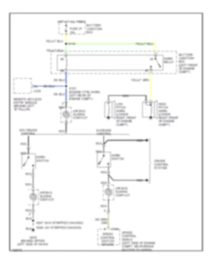
Horn Wiring Diagram for Ford Econoline E250 2000
List of elements for Horn Wiring Diagram for Ford Econoline E250 2000:
- (w/ stripped chassis)
- (w/o stripped chassis)
- 15a
- Air bag sliding contact
- Battery junction box
- Battery junction box (left front of engine compt)
- C146
- C335
- Cruise control system
- Fuse 27
- G202 (behind upper left side of dash)
- High pitch horn (lower right front of engine compt)
- Horn relay
- Horn switch
- Hot at all times
- Low pitch horn (lower right front of engine compt)
- Nca
- Remote keyless entry module (behind left "b" pillar)
- S116
- S121 (engine ctrl harn, left rear of engine compt)
- S207
- S286
- Speed control servo (left side of engine compt, near brake master cylinder)
- Speed control switch ground
- W/cruise control
- W/o cruise control
 Čeština
 Dansk
Dansk Deutsch
 Ελληνικά
 English
 English
 Suomi
Suomi Français
 Français
 עברית
עברית Hrvatski
 Magyar
 Italiano
 日本語
日本語 한국어
한국어 Nederlands
 Polski
 Português
 Português
 Română
 Русский
 Slovenčina
 Slovenščina
 Svenska
 Türkçe
 中文 (中国)
 Español