POWER DISTRIBUTION
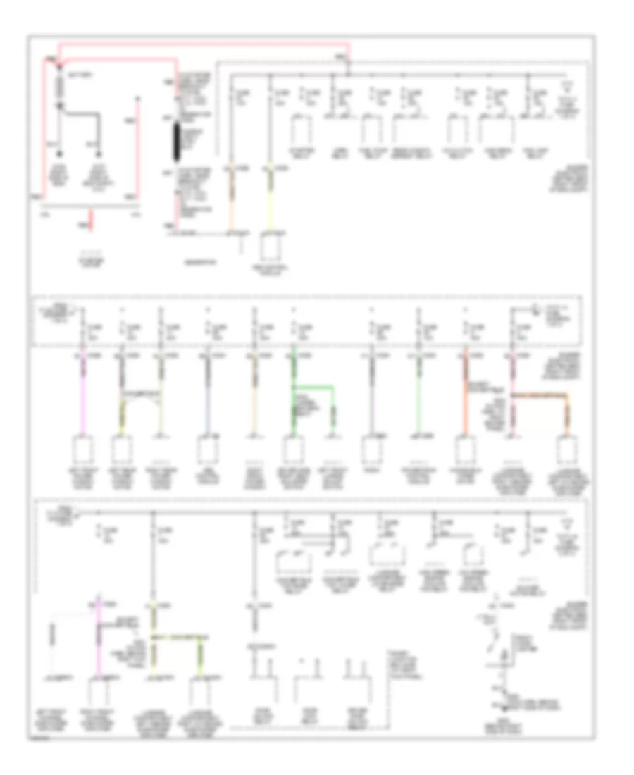
Power Distribution Wiring Diagram (1 of 4) for Ford Mustang GT 2005
List of elements for Power Distribution Wiring Diagram (1 of 4) for Ford Mustang GT 2005:
- (4.0l) (4.6l)
- (convertible)
- (except convertible)
- (in starter harn, near breakout to g106) s118 s111 (in generator harn)
- (in starter harn, near red breakout to g106) s117 s110 (in generator harn)
- 1035a d5
- 1035d
- 175b
- 290d
- 4.0l
- 4.6l
- A/c clutch relay
- Abs control module
- Battery
- Blower motor relay
- Bussed electrical center (bec) (right front of eng compt)
- C102a
- C102b
- C135
- C2280h
- C2993a
- C2994a
- C4158a
- C4160a
- Convertible
- Convertible top lower relay
- Convertible top raise relay
- Door lock relay
- Door unlock relay
- Driver door unlock relay
- Driver side front seat adjuster switch
- Fog lamp relay
- From f1.58 fuse a (diagram 1 of 4)
- From f1.8 fuse b (diagram 1 of 4)
- Front cigar lighter
- Fuel pump relay
- Fuse 10a
- Fuse 15a
- Fuse 20a
- Fuse 25a
- Fuse 30a
- Fuse 40a
- G106 (right side of eng)
- G107 (right side of eng compt) (4.0l)
- G200 (behind right side of dash)
- Generator
- Harn, at right rocker panel)
- High beam relay
- High speed engine cooling fan relay
- Horn relay
- Left front channel subwoofer amplifier
- Left front lumbar adjust switch
- Left front power window motor
- Left rear power window motor
- Low speed engine cooling fan relay
- Luggage compartment left inboard subwoofer amplifier
- Luggage compartment left outboard subwoofer amplifier
- Luggage compartment lid release relay
- Luggage compartment right inboard subwoofer amplifier
- Luggage compartment right outboard subwoofer amplifier
- Powertrain control module
- Radio
- Rear window defrost relay
- Red
- Right front channel subwoofer amplifier
- Right front power window
- Right rear power window motor
- S221 (in main harn, behind right kick panel)
- S411
- S412
- Seat)
- Smart junction box (sjb) (at right kick panel)
- Starter motor
- Starter relay
- To f1.14 fuse (diagram 1 of 4)
- To f1.4 fuse (diagram 1 of 4)
- To f1.44 fuse (diagram 2 of 4)
- Windshield wiper motor
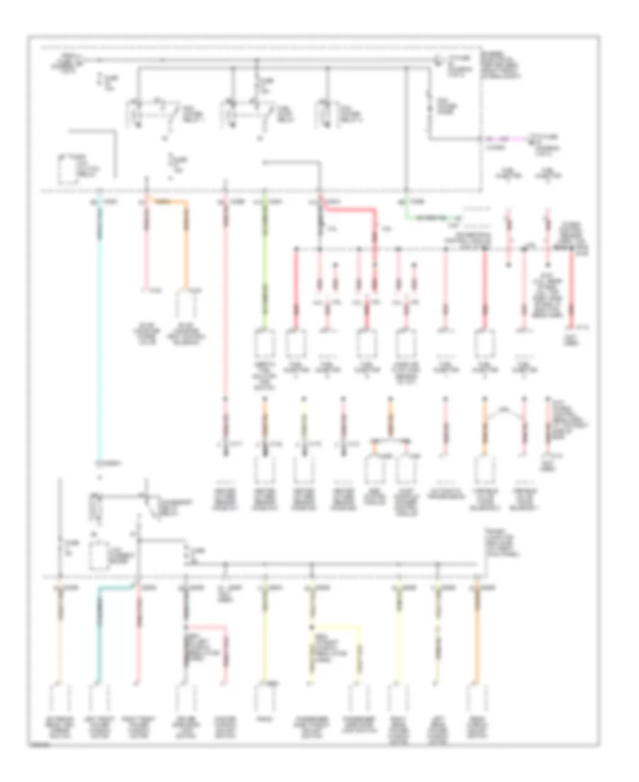
Power Distribution Wiring Diagram (2 of 4) for Ford Mustang GT 2005
List of elements for Power Distribution Wiring Diagram (2 of 4) for Ford Mustang GT 2005:
- (in eng control sensor harn, top rear of eng)
- (not used)
- 1035a
- 1035a b2
- 1035b e6
- 175t
- 2280f (not used)
- 2280g
- 290d
- 4.0l
- 4.6l
- A/c clutch relay
- Accessory delay relay
- Automatic transmission
- Bussed electrical center (bec) (right front of eng compt)
- C1008
- C1035a
- C110
- C116
- C123
- C141
- C142
- C1450
- C171
- C172
- C191
- C2280h
- Driver side door lock switch
- Egr system module
- Evap canister purge valve
- Evap canister vent control solenoid
- Exterior rear view mirror switch
- From fuse 1 c (diagram 1 of 4)
- Fuel injector
- Fuel pump relay
- Fuse 10a
- Fuse 15a
- Fuse 5a
- Heated oxygen sensor (ho2s) #11
- Heated oxygen sensor (ho2s) #12
- Heated oxygen sensor (ho2s) #21
- Heated oxygen sensor (ho2s) #22
- Inertia fuel shutoff (ifs) switch
- Inlet manifold runner control module
- Left front power window motor
- Left rear power window motor
- Low current board
- Mass air flow (maf) sensor (w/ a/t)
- Master window adjust switch
- Nca
- Passenger side door lock switch
- Passenger side window adjust switch
- Pcm power diode
- Pcm power relay 1
- Pcm power relay 2
- Powertrain control module (4.0l w/ m/t)
- Radio
- Rear window adjust switch
- Red
- Right front power window motor
- Right rear power window motor
- S101 (in eng control sens harn, at top right side of eng)
- S107 (4.0l: rear of eng, 4.6l: top right side of eng, in eng ctrl sens harn)
- S109
- S603 (in right window regulator harn)
- Smart junction box (sjb) (at right kick panel)
- To fuse (diagram 3 of 4)
- To fuse (diagram 4 of 4)
- Variable valve timing solenoid 1
- Variable valve timing solenoid 2
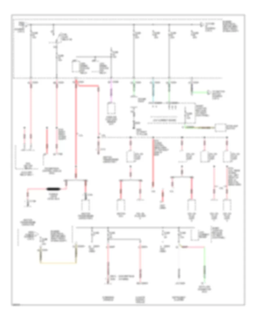
Power Distribution Wiring Diagram (3 of 4) for Ford Mustang GT 2005
List of elements for Power Distribution Wiring Diagram (3 of 4) for Ford Mustang GT 2005:
- (convertible)
- (not used)
- (others)
- 1035a
- 1035a a2 red
- 1035a b6 red
- 1035b d5
- 175b
- 2280a
- 2280f
- 2280h
- 4.0l
- 4.6l
- Auxiliary relay box 1
- Bussed electrical center (bec) (right front of eng compt)
- C1196
- C174
- C194
- C220
- C2280h
- C294a
- C390
- C9013
- Climate control module
- Coil on plug (cop)
- Data link connector (dlc)
- From fuse 63 f (diagram 3 of 4)
- From fuse d (diagram 2 of 4)
- Fuel pump relay #2
- Fuse
- Fuse 10a
- Fuse 15a
- Fuse 20a
- Fuse 30a
- Fuse 5a
- G203 (at right "a" pillar)
- High speed cooling fan relay
- Ignition coil
- Ignition transformer capacitor
- Ignition transformer capacitor 1
- Ignition transformer capacitor 2
- Instrument cluster
- Low current board
- Low speed cooling fan relay
- Mass air flow (maf) sensor (m/t)
- Nca
- Overhead console
- Pcm key-off relay
- Power point
- Powertrain control module (pcm)
- Red
- S101 (in eng control sens harn, at top right side of eng)
- S104 (4.0l: rear of eng, 4.6l: left front of eng, in eng ctrl sens harn)
- S120 (right front of eng compt)
- Smart junction box (sjb) (at right kick panel)
- Stoplamp switch
- To fuse (diagram 3 of 4)
- To ignition switch (diagram 4 of 4)
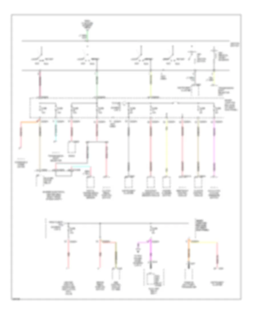
Power Distribution Wiring Diagram (4 of 4) for Ford Mustang GT 2005
List of elements for Power Distribution Wiring Diagram (4 of 4) for Ford Mustang GT 2005:
- (not used)
- 1035a c3
- A/c clutch cycling pressure switch
- A/t
- Abs control module (w/ abs)
- Acc
- Auxiliary relay box 1
- Blower motor relay
- Brake pedal position switch
- Bussed electrical center (bec) (right front of eng compt)
- C1035a a9
- C1035b b9
- C135
- C2041a
- C207
- C215
- C220
- C2280a
- C2280h
- C290d
- C294a
- Climate control module
- Clutch pedal position switch
- Digital transmission range (dtr) sensor
- From f1.68 fuse (diagram 3 of 4)
- From fuse j (diagram 4 of 4)
- Fuse 10a
- Fuse 5a
- Hazard flasher switch
- Heated positive crankcase ventilation (pcv) valve
- Ignition switch
- Instrument cluster
- Key in ignition switch
- Key removal inhibit solenoid
- Lock
- M/t
- Nca
- Occupant classification sensor module
- Passive anti-theft transceiver
- Pcm key- off relay diode
- Radio
- Red
- Restraint control module
- Run
- Smart junction box (sjb) (at right kick panel)
- Smart smart junction junction box (sjb) box (sjb) (at right (at right kick panel) kick panel)
- Start
- To fuse (diagram 4 of 4)
- To pcm power diode, (diagram 2 of 4)
- Transmission shift selector
- Transmission shift selector (a/t)
- Windshield wiper motor

 Čeština
 Dansk
Dansk Deutsch
 Ελληνικά
 English
 English
 Suomi
Suomi Français
 Français
 עברית
עברית Hrvatski
 Magyar
 Italiano
 日本語
日本語 한국어
한국어 Nederlands
 Polski
 Português
 Português
 Română
 Русский
 Slovenčina
 Slovenščina
 Svenska
 Türkçe
 中文 (中国)