POWER DISTRIBUTION
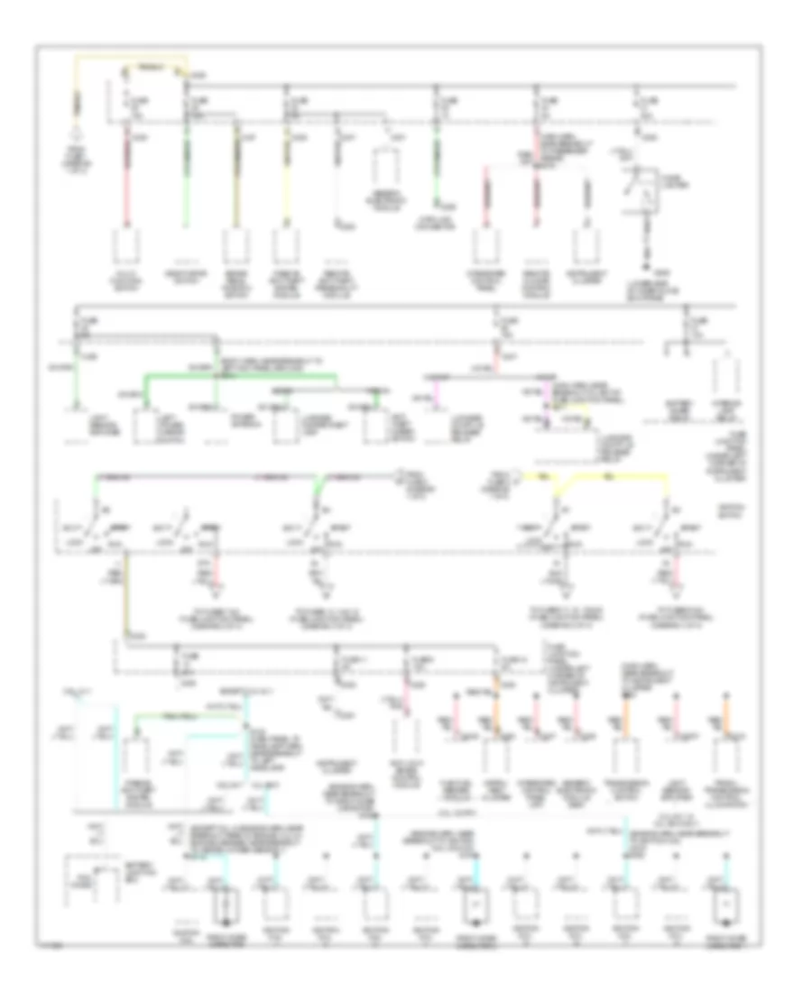
Power Distribution Wiring Diagram (1 of 3) for Mercury Sable LS 1999
 https://portal-diagnostov.com/license.html
Automotive Electricians Portal FZCO
Automotive Electricians Portal FZCO
https://portal-diagnostov.com/license.html
https://portal-diagnostov.com/license.html
Automotive Electricians Portal FZCO
Automotive Electricians Portal FZCO
List of elements for Power Distribution Wiring Diagram (1 of 3) for Mercury Sable LS 1999:
- (body harn, near breakout to safety belt buckle switch) s325 red
- (dash panel to headlamp junction harn, in breakout left of master cylinder) s139
- (main harn, near breakout to semi-active ride control module)
- 10a
- 175a
- 3.4l sho
- A/c clutch relay
- Anti-lock brake control module
- Autolamp headlamp relay
- Autolamp park relay
- Battery
- Battery junction box (front center of engine compt, behind radiator)
- Blower motor relay
- Cellular phone in-line fuse (in cargo area, above left rear wheelwell)
- Cellular phone support electronics
- Circuit breaker 30a
- Compact disc changer
- Daytime running lamps module
- Eam solid state relay
- Electronic crash unit
- Fuel pump relay
- Fuse 10a
- Fuse 15a
- Fuse 20a
- Fuse 30a
- Fuse 40a
- Generator
- Headlamp switch
- High speed cooling fan relay
- Horn relay
- Left lumbar seat switch
- Left seat control switch
- Low speed cooling fan relay
- Mega fuse (right side of battery junction block)
- Multi- function switch
- Nca
- Pcm relay
- Powertrain control module
- Rear control unit
- Red
- Right seat switch
- S128 (dash panel to headlamp harn, near breakout to battery junction box)
- S132 (dash panel to headlamp junction harn, near breakout to anti-lock brake control module)
- S414 (body harn, left rear wheelwell)
- S423 (radio amplifier harn, left rear wheelwell)
- Semi-active ride control module
- Starter motor
- Starter relay
- Tan/red
- To fuse 29 (fuse junction panel) (diagram 2 of 3)
- To fuse junction panel (accessory delay relay) (diagram 3 of 3)
- To ignition switch (pins b1 & b3) (diagram 2 of 3)
- To ignition switch (pins b4 & b5) (diagram 2 of 3)
- To rear window defrost relay (fuse junction panel) (diagram 3 of 3)
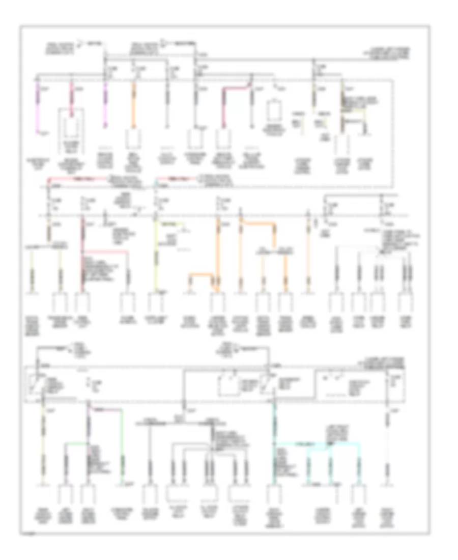
Power Distribution Wiring Diagram (2 of 3) for Mercury Sable LS 1999
List of elements for Power Distribution Wiring Diagram (2 of 3) for Mercury Sable LS 1999:
- (body harn, near breakout to left kick panel ground) s313
- (diagram 1 of 3)
- (engine harn, near breakout to ignition coil 5 & no 6) s161
- (engine harn, near breakout to radio noise capacitor) s163
- (fuse junction panel) (diagram 3 of 3)
- (lower side of inner glove box frame)
- (main harn, near breakout to instrument cluster) s224
- (main harn, near breakout to left of fuse junction panel) s211
- 20a
- 3.0l 12v ffv
- 3.0l 24-v & 3.4l sho only
- 3.0l 24v
- 3.4l sho
- 3.ol 12 v
- Acc
- Anti- theft disarm switch
- Anti-lock brake control module
- Battery junction box
- Battery saver relay
- Brake pedal position switch
- C2007
- C201
- C2040
- C225
- C229
- C235
- C236
- C237
- C247
- C250
- C251
- C254
- C318
- Cigar lighter
- Data link connector
- Deactivator switch
- Except 3.ol 12 v
- Flex fuel sender module
- From fuse 1 (diagram 1 of 3)
- From fuse 3 (diagram 1 of 3)
- From fuse 5 c
- Fuse
- Fuse 10a
- Fuse 11 5a
- Fuse 12 5a
- Fuse 15a
- Fuse 20a
- Fuse 5a
- Fuse 9 10a
- Fuse junction panel (under left corner of instrument cluster)
- G206
- Generic electronic module
- Generic electronic module (gem)
- Ignition coil
- Ignition coil
- Ignition switch
- Instru- ment cluster
- Instrument cluster
- Integrated control panel
- Integrated control panel (icp)
- Interior lamp relay
- Left power mirror switch
- Light sensor/ amplifier
- Lock
- Luggage compartment lamp
- Luggage compt lid release relay
- Multi- function switch
- Off
- Passive anti-theft system module
- Pcm diode
- Power antenna
- Prndl/ transmission control illumination
- Radio noise capacitor
- Radio noise capacitor 1
- Radio noise capacitor 2
- Remote anti-theft personality module
- Remote climate control module
- Run
- Sedan
- Sta
- Start
- To fuses 13, 14 & 15 (fuse junction panel) (diagram 3 of 3)
- To fuses 17, 18, 19 & 20 (fuse junction panel) (diagram 3 of 3)
- To fuses 5 & 6
- To fuses 7 & 8 (fuse junction panel) (diagram 3 of 3)
- To left headlamp)
- Transmission control switch
- W/ rap
- W/o rap
- Wagon
Power Distribution Wiring Diagram (3 of 3) for Mercury Sable LS 1999
List of elements for Power Distribution Wiring Diagram (3 of 3) for Mercury Sable LS 1999:
- (body harn, near breakout at right side of steering column) s204
- (body harn, near breakout in right rear pillar) s409
- (left front door harn, left front door jamb) s504
- (not used)
- (under left corner of instrument cluster) fuse junction panel
- 3.0l 12v
- 3.0l 24v 3.4l sho
- 3.0l 3.0l 12v
- Accessory delay relay
- All door lock relay
- All door unlock relay
- Blend door actuator
- Blower motor relay
- C201
- C225
- C235
- C237
- C247
- C251
- C277
- C501
- C509
- Cellular phone support electronics
- Daytime running lamps module
- Digital trans- mission range sensor
- Driver's unlock relay
- Electronic crash unit
- Engine compartment fuse/relay box
- From ignition g
- From ignition h
- From fuse 4 (diagram 1 of 3)
- From fuse 7 (diagram 1 of 3)
- From ignition switch (pin a3) (diagram 2 of 3)
- From ignition switch (pin sta) (diagram 2 of 3)
- Fuse 10a
- Fuse 15a
- Fuse 30a
- Fuse 5a
- Generic electronic module
- Generic electronic module (gem)
- Heater function selection mode switch
- Instrument cluster
- Integrated control panel
- Left master door lock switch
- Left power/ heated mirror
- Liftgate unlock relay (wagon w/ rap)
- Liftgate washer pump motor
- Liftgate wiper motor
- Liftgate wiper/ washer control
- Master window control switch
- Multi- function switch
- Nca
- One touch window down relay
- Power antenna
- Rear control unit
- Rear window defrost grid
- Rear window defrost relay
- Remote anti-theft personality module
- Remote climate control module
- Right master door lock switch
- Right power/ heated mirror
- Roof opening panel drive assembly
- S203 (body harn, near breakout at left kick panel)
- S309 (body harn, near breakout at left kick panel)
- S413 (body harn, near breakout at middle section of left rear quarter panel)
- Sedan
- Semi- active ride control module
- Shift lock actuator
- Speed control module
- Switch (pin a1) (diagram 2 of 3)
- Switch (pin a4) (diagram 2 of 3)
- Tailgate release switch
- Trans- mission range sensor
- Transmission range sensor
- Wagon
- Wagon w/o doorlocks
- Washer motor relay
- Wind- shield wiper motor
- Wiper hi/lo relay
- Wiper park relay

 Čeština
 Dansk
Dansk Deutsch
 Ελληνικά
 English
 English
 Suomi
Suomi Français
 Français
 עברית
עברית Hrvatski
 Magyar
 Italiano
 日本語
日本語 한국어
한국어 Nederlands
 Polski
 Português
 Português
 Română
 Русский
 Slovenčina
 Slovenščina
 Svenska
 Türkçe
 中文 (中国)