SUPPLEMENTAL RESTRAINTS
Supplemental Restraint Wiring Diagram for Mercury Sable GS 1997
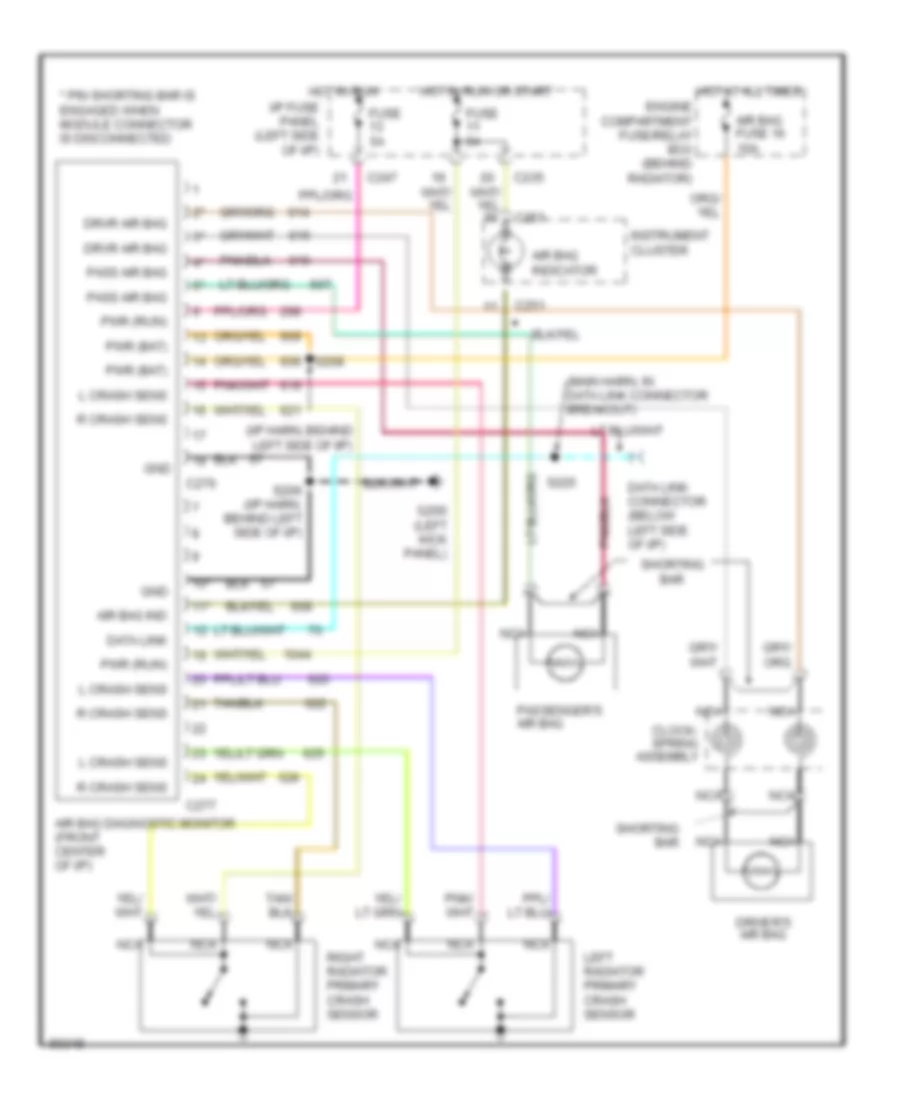
List of elements for Supplemental Restraint Wiring Diagram for Mercury Sable GS 1997:
- (i/p harn, behind left side of i/p)
- (main harn, in data link connector breakout)
- * pin shorting bar is engaged when module connector is disconnected
- 10*
- 11*
- Air bag diagnostic monitor (front center of i/p)
- Air bag fuse 16 10a
- Air bag ind
- Air bag indicator
- C235
- C247
- C251
- C276
- C277
- Clock- spring assembly
- Data link
- Data link connector (below left side of i/p)
- Driver's air bag
- Drvr air bag
- Engine compartment fuse/relay box (behind radiator)
- Fuse 5a
- G200 (left kick panel)
- Gnd
- Hot at all times
- Hot in run
- Hot in run or start
- I/p fuse panel (left side of i/p)
- Instrument cluster
- L crash sens
- Left radiator primary crash sensor
- Nca
- Pass air bag
- Passenger's air bag
- Pwr (bat)
- Pwr (run)
- R crash sens
- Right radiator primary crash sensor
- S206 (i/p harn, behind left side of i/p)
- S208
- S225
- Shorting bar
 Čeština
 Dansk
Dansk Deutsch
 Ελληνικά
 English
 English
 Suomi
Suomi Français
 Français
 עברית
עברית Hrvatski
 Magyar
 Italiano
 日本語
日本語 한국어
한국어 Nederlands
 Polski
 Português
 Português
 Română
 Русский
 Slovenčina
 Slovenščina
 Svenska
 Türkçe
 中文 (中国)
 Español