СИСТЕМА УСИЛИТЕЛЯ РУЛЯ
Электросхема усилителя руля для Pontiac Grand Prix GTP 1997
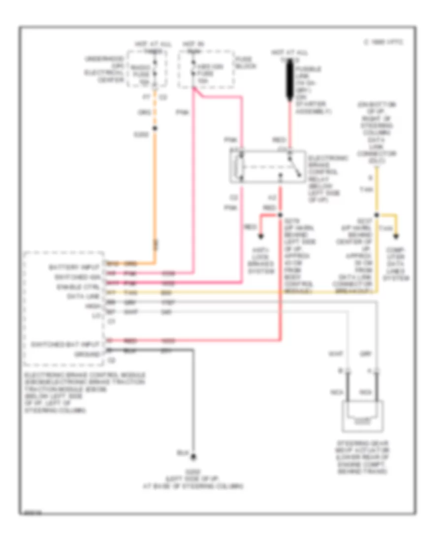
Электросхема усилителя руля для Pontiac Grand Prix GTP 1997 - Список элементов:
- (on bottom of i/p, right of steering column) data link connector (dlc)
- 1995 vftc c
- A11
- Abs ign fuse 10a
- Anti- lock brakes system
- B12
- Battery input
- Comp- uter data lines system
- Data line
- Electronic brake control module (ebcm)/electronic brake traction traction module (ebcm) (below left side of i/p, left of steering column)
- Electronic brake control relay (below left side of i/p)
- Enable ctrl
- Fuse block
- G202 (left side of i/p, at base of steering column)
- Ground
- High
- Hot at all times
- Hot in run
- Nca
- Pnk
- Radio fuse 10a
- Red
- S202
- S237 (i/p harn, behind center of i/p, approx 30 cm from data link connector breakout)
- S279 (i/p harn, behind left side of i/p, approx 43 cm from body control module)
- Steering gear msvp actuator (lower rear of engine compt, behind trans)
- Switched bat input
- Switched ign
- Tan
- Underhood (uh) electrical center
 Čeština
 Dansk
Dansk Deutsch
 Ελληνικά
 English
 English
 Suomi
Suomi Français
 Français
 עברית
עברית Hrvatski
 Magyar
 Italiano
 日本語
日本語 한국어
한국어 Nederlands
 Polski
 Português
 Português
 Română
 Русский
 Slovenčina
 Slovenščina
 Svenska
 Türkçe
 中文 (中国)
 Español