ENGINE PERFORMANCE
2.5L
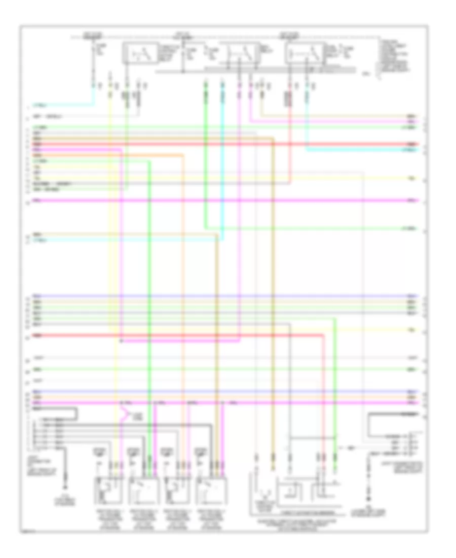
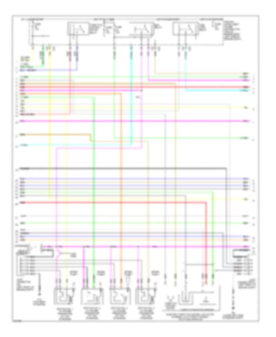
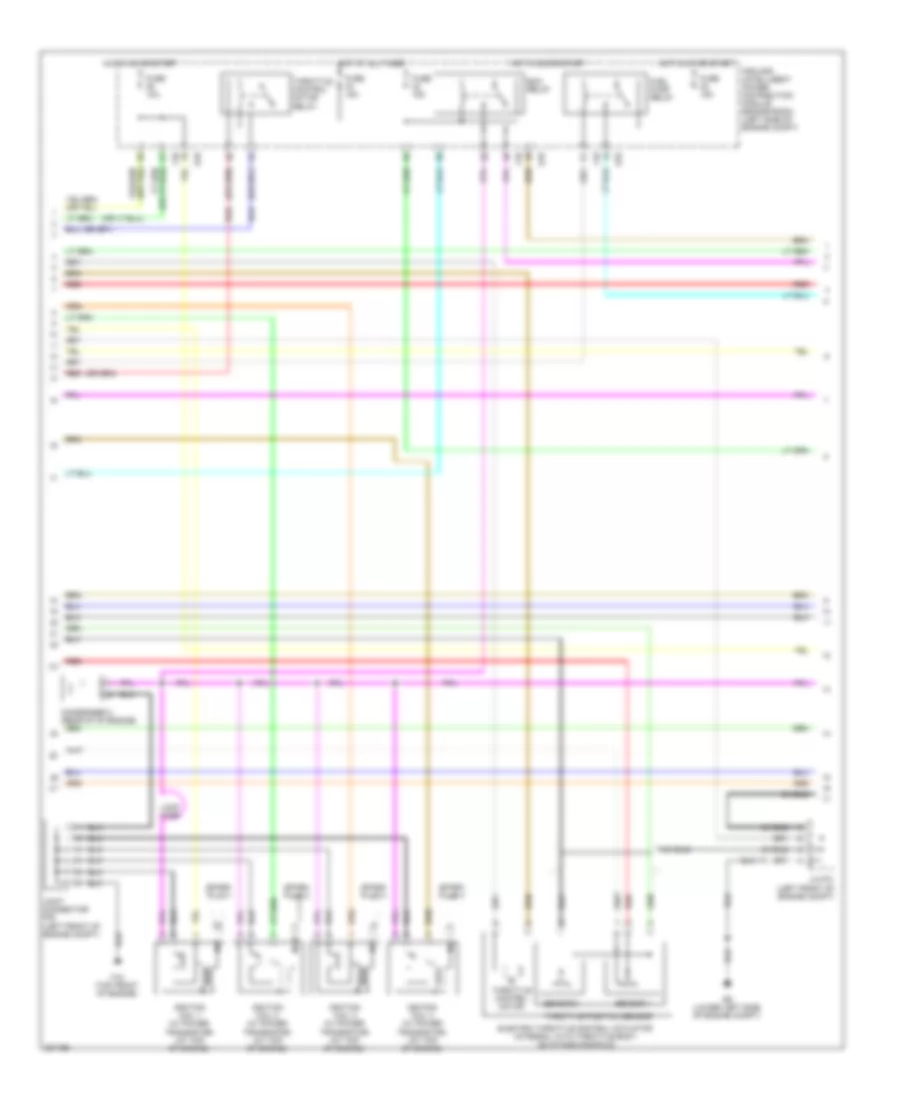
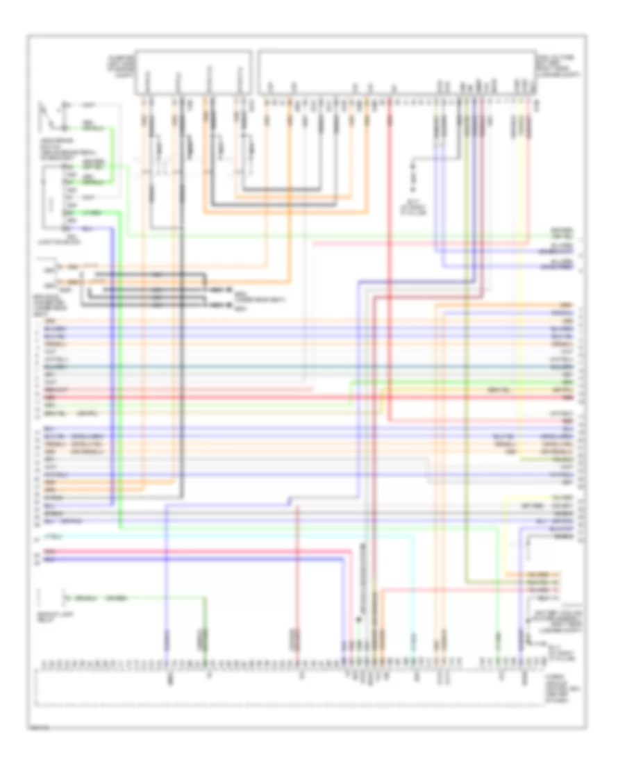
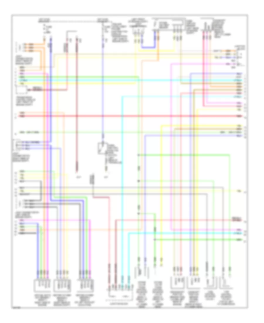
2.5L, Engine Controls Wiring Diagram, Hybrid (1 of 4) for Nissan Altima S 2010
 https://portal-diagnostov.com/license.html
Automotive Electricians Portal FZCO
Automotive Electricians Portal FZCO
https://portal-diagnostov.com/license.html
https://portal-diagnostov.com/license.html
Automotive Electricians Portal FZCO
Automotive Electricians Portal FZCO
List of elements for 2.5L, Engine Controls Wiring Diagram, Hybrid (1 of 4) for Nissan Altima S 2010:
- (behind left end of dash)
- (left front of engine compt) joint connector f05
- (or red)
- (top of engine) fuel injectors
- 12m
- 3rdo2h
- 3rdo2s
- Af+1
- Af-1
- Afh1
- Avcc1-tps-b1
- Avcc2
- Combination meter
- Computer data lines system
- Condenser 2 (rear of of engine)
- E18
- E9 (lower left side of engine compt)
- Ecm
- Engine coolant temperature sensor (left rear of engine)
- Evap
- Evap canister purge volume control solenoid valve (on intake manifold, near throttle body)
- F13
- F14
- Fpr
- Fuse 10a
- Fuse block (j/b)
- Gnd
- Gnda-o2sr2
- Gnda-pdpres
- Gnda-ta1
- Gnda-tps-b1
- Gnda-tw
- Hot in on or start
- Ign 1
- Ign 2
- Ign 3
- Ign 4
- Inj 1
- Inj 2
- Inj 3
- Inj 4
- Ipdm e/r (intelligent power distribution e201
- M57 (behind left end of dash)
- Malfunction indicator lamp (mil)
- Module engine room) (left side of engine compt)
- Motor1-b1
- Motor2-b1
- Motrly-b1
- O2hr1
- Osr1
- Pdpres
- Pnk
- Red
- Refrigerant pressure sensor (left front of engine compt)
- Sig
- Ssof
- Ta1
- Tps1-b1
- Tps2-b1
- Unified meter control unit (w/ information display)
- Vmot-b1
- Vscv
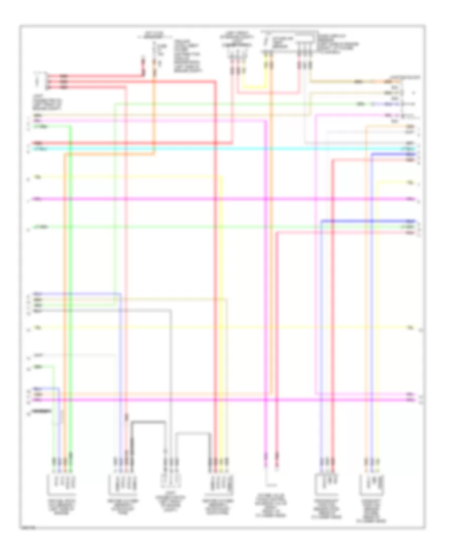
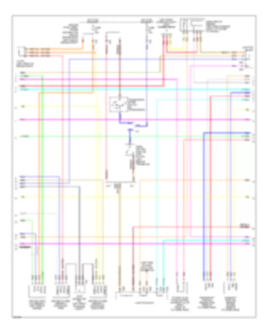
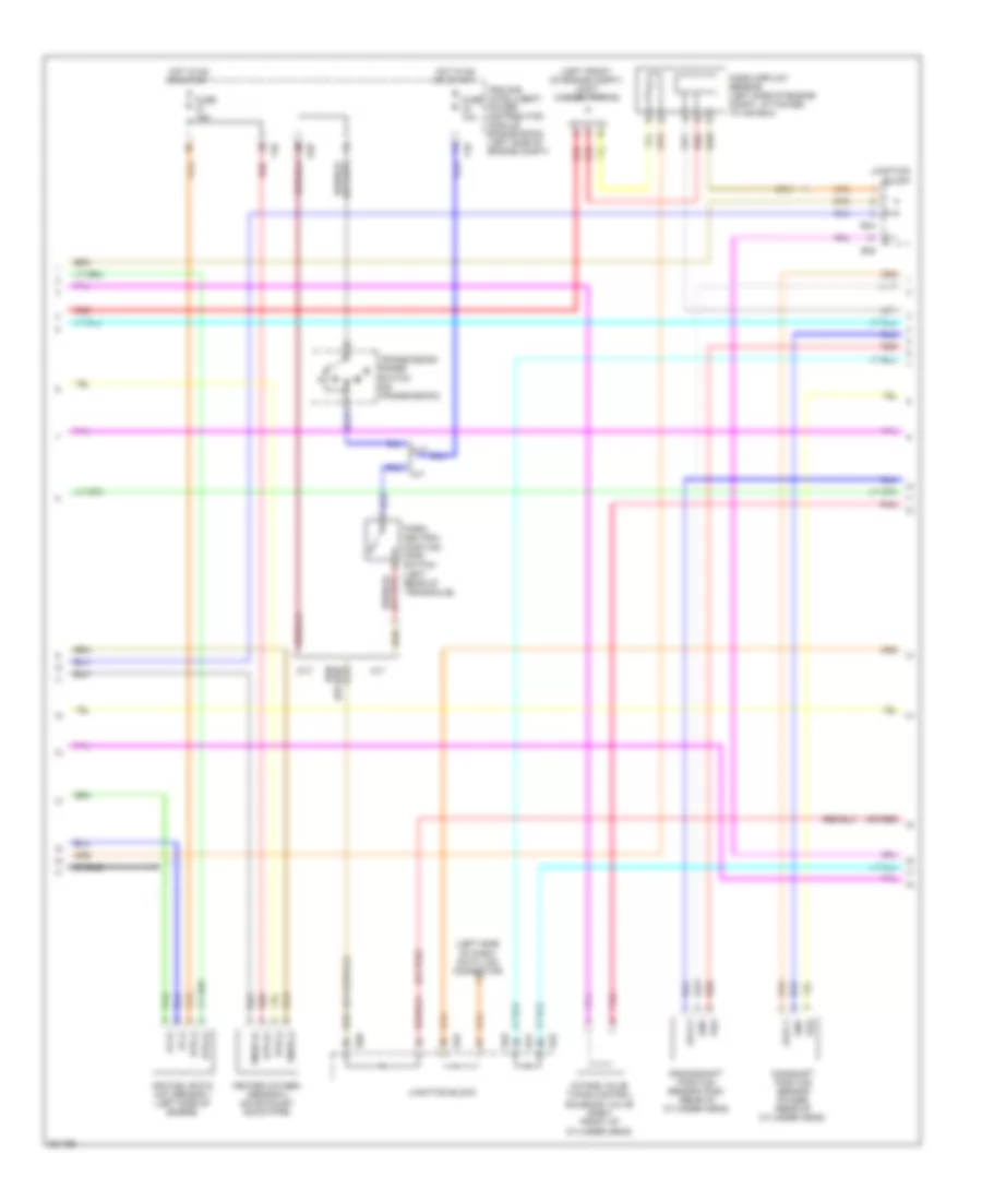
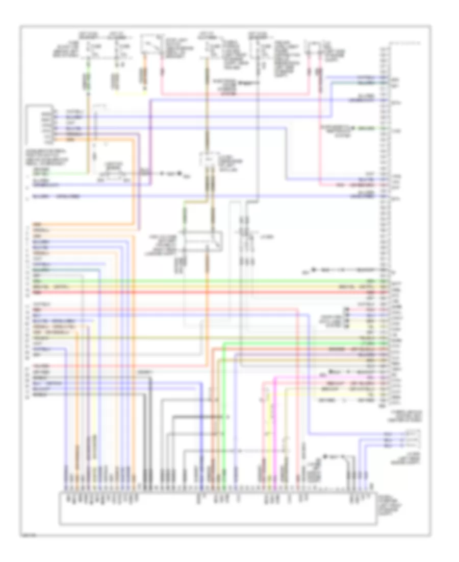
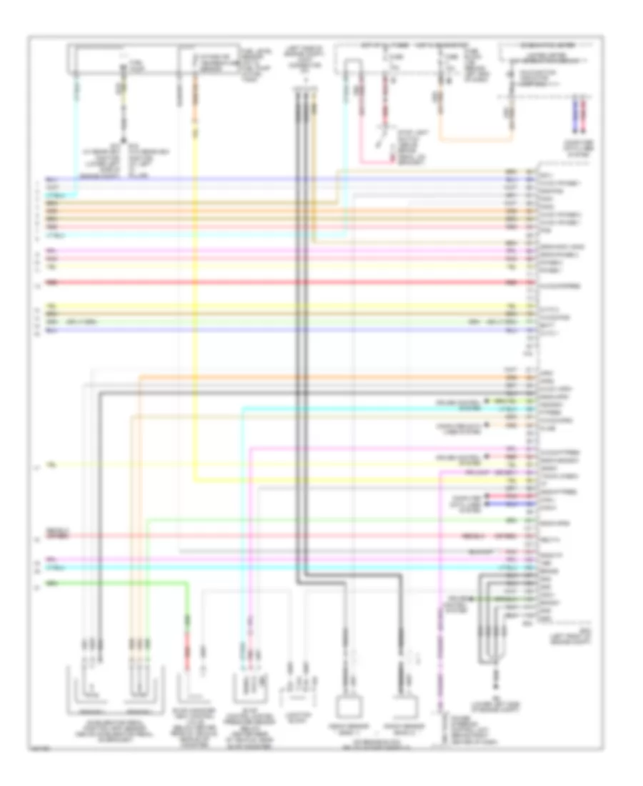
2.5L, Engine Controls Wiring Diagram, Hybrid (2 of 4) for Nissan Altima S 2010
List of elements for 2.5L, Engine Controls Wiring Diagram, Hybrid (2 of 4) for Nissan Altima S 2010:
- (or red)
- Cpu
- E18
- E9 (lower left side of engine compt)
- Ecm relay
- Electric throttle control actuator (integral with throttle body, on intake manifold)
- F10
- F15 (top front of engine)
- Fuel pump relay
- Fuse 10a
- Fuse 15a
- Hot at all times
- Hot in on or start
- Ignition coil 1 (w/ power transistor) (at top of engine)
- Ignition coil 2 (w/ power transistor) (at top of engine)
- Ignition coil 3 (w/ power transistor) (at top of engine)
- Ignition coil 4 (w/ power transistor) (at top of engine)
- Ipdm e/r (intelligent power distribution module engine room) (left side of engine compt)
- Joint connector f01 (left front of engine compt)
- Joint connector f03 (left front of engine compt)
- Loop wire
- Red
- Shield
- Spark plug 1
- Spark plug 2
- Spark plug 3
- Spark plug 4
- Throttle control motor
- Throttle control motor relay
- Throttle position sensor
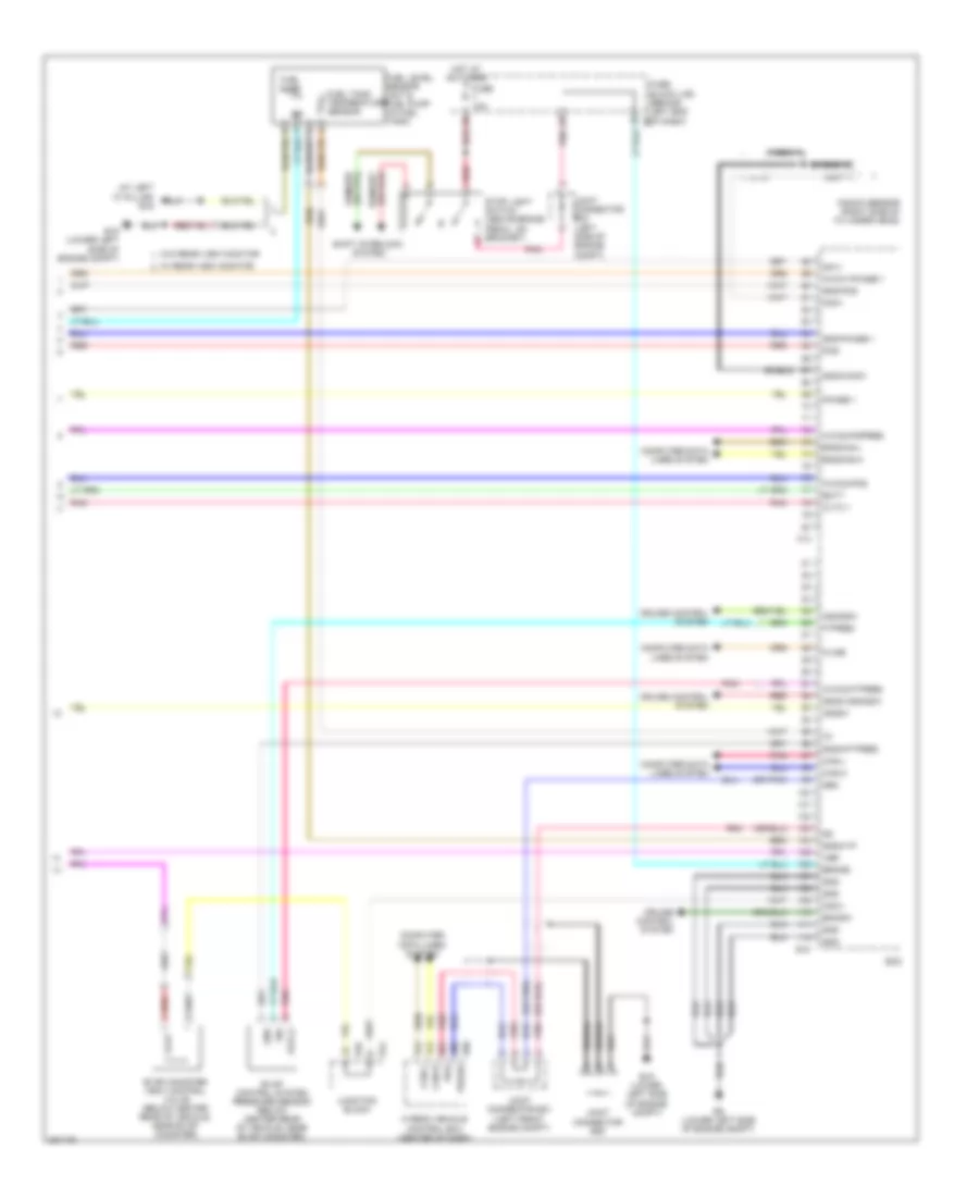
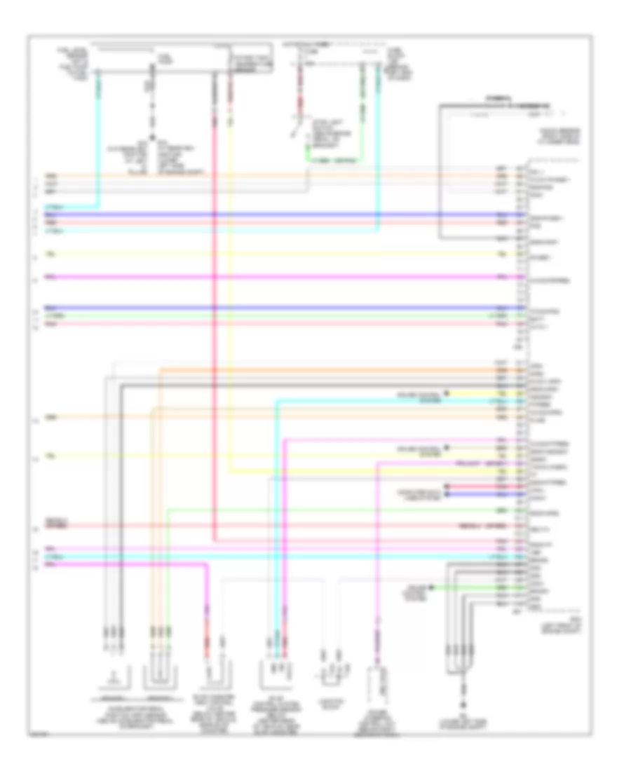
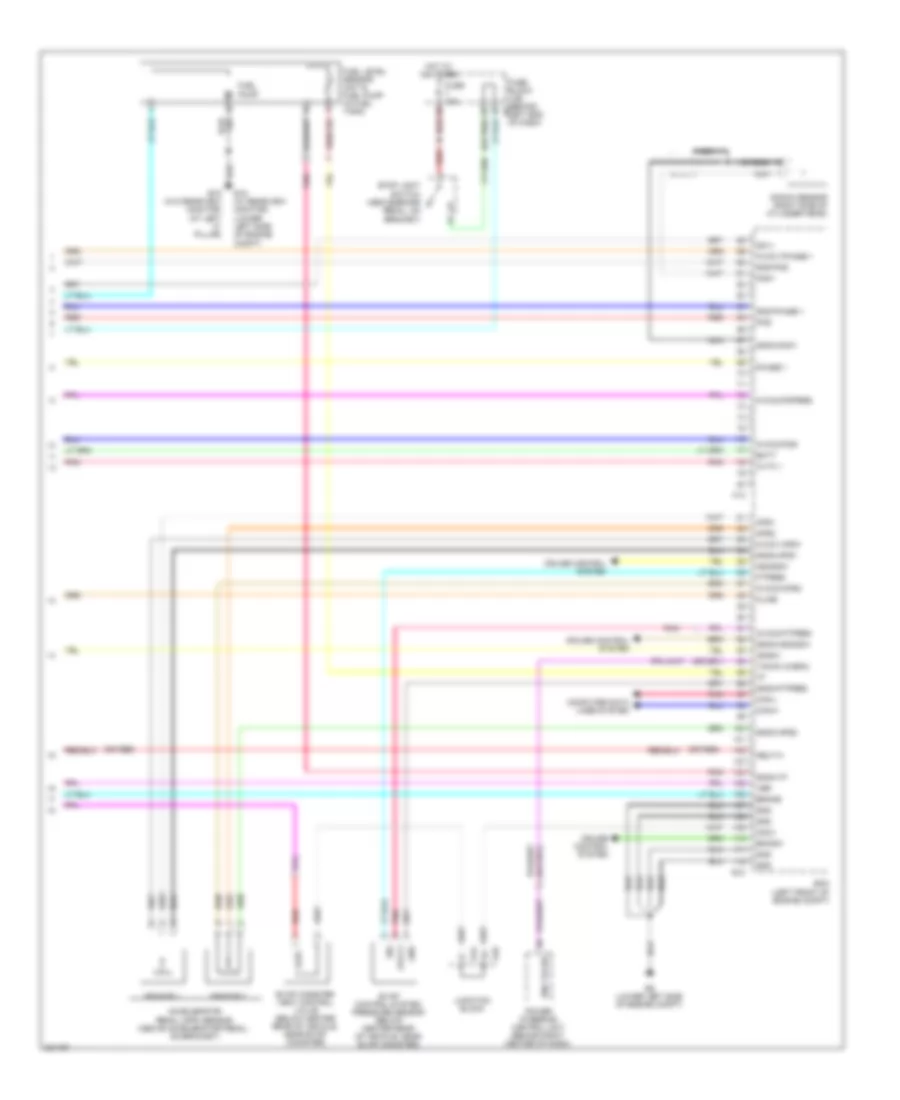
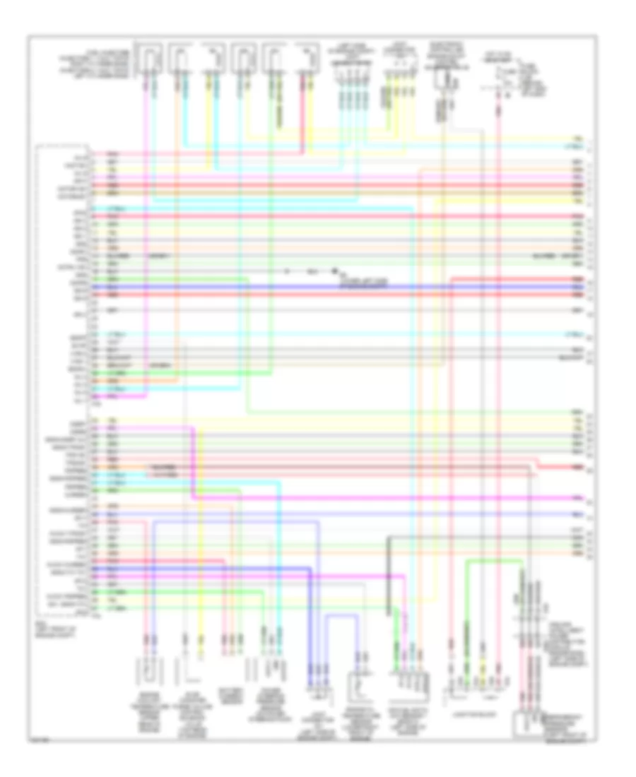
2.5L, Engine Controls Wiring Diagram, Hybrid (3 of 4) for Nissan Altima S 2010
List of elements for 2.5L, Engine Controls Wiring Diagram, Hybrid (3 of 4) for Nissan Altima S 2010:
- (left front of engine compt) joint connector f03
- Af (+)
- Af (-)
- Air fuel ratio (a/f) sensor 1 (left side of engine)
- Avcc1
- Avcc2
- Camshaft position sensor (phase) (rear of cylinder head)
- Crankshaft position sensor (pos) (rear of cylinder head)
- E44
- E45
- F10
- Fuse 15a
- Gnd
- Heated oxygen sensor 2 (on exhaust down pipe)
- Heated oxygen sensor 3 (in exhaust pipe)
- Hot in on or start
- Htr (+)
- Htr (-)
- Intake air temp sensor
- Intake valve timing control solenoid valve (right front of cylinder head)
- Ipdm e/r (intelligent power distribution module engine room) (left side of engine compt)
- Joint connector f03 (left front of engine compt)
- Joint connectro f01 (left front of engine compt)
- Junction block
- Mass airflow sensor (left side of engine compt, attached to air box)
- Phase
- Pnk
- Pos
- Red
- Sens (+)
- Sens (-)
- Shield
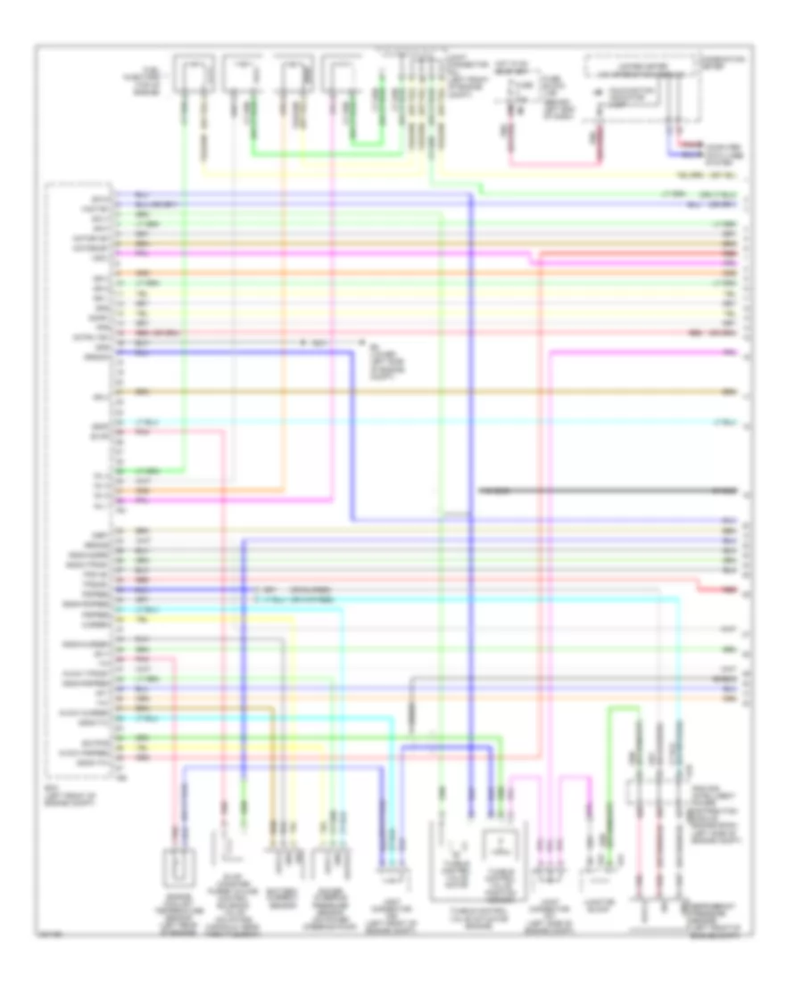
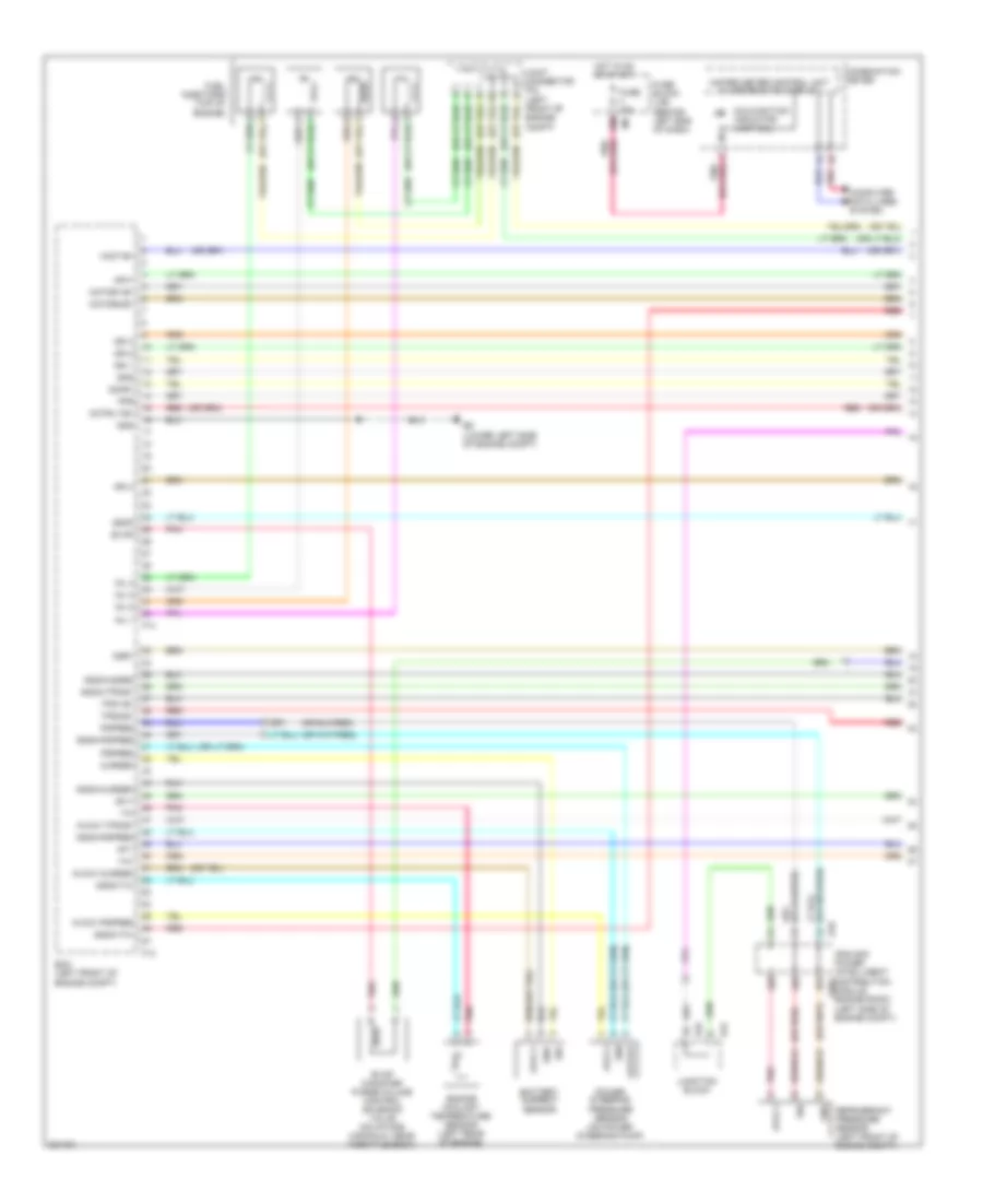
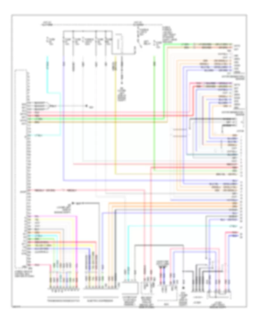
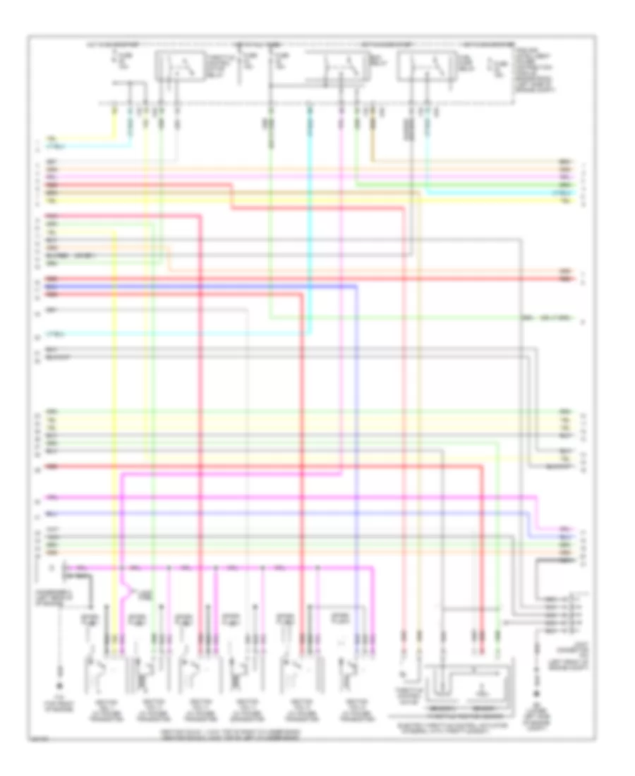
2.5L, Engine Controls Wiring Diagram, Hybrid (4 of 4) for Nissan Altima S 2010
List of elements for 2.5L, Engine Controls Wiring Diagram, Hybrid (4 of 4) for Nissan Altima S 2010:
- (at left "c" pillar) b19
- (or pnk)
- Ascdsw
- Avcc1-phase 1
- Avcc2
- Avcc2-ftpres
- Avcc2-pdpres
- Avcc2-pos
- Batt
- Bncsw
- Brake
- Can-h
- Can-l
- Cdcv
- Computer data lines system
- Cruise control system
- Cvtc 1
- E10
- E15 (lower left side of engine compt)
- E44
- E45
- E66
- E9 (lower left side of engine compt)
- Ecm
- Engcan-h
- Engcan-l
- Evap canister vent control valve (below center rear of vehicle, near evap canister)
- Evap control system pressure sensor (below center rear of vehicle, near evap canister)
- F13
- Ftpres
- Fuel level sensor unit & fuel pump (in fuel tank)
- Fuel pump
- Fuel tank temperature sensor
- Fuse 10a
- Fuse block (j/b) (behind left end of dash)
- Gnd
- Gnd-phase 1
- Gnd-pos
- Gnda-ascdsw
- Gnda-ftpres
- Gnda-knk1
- Gnda-tf
- Hot at all times
- Hybrid vehicle control ecu (center of dash)
- Ignsw
- Joint connector e01 (left front engine compt)
- Joint connector e04 (left side of engine compt)
- Joint connector e08
- Junction block
- Kline
- Knk1
- Knock sensor (right side of cylinder head)
- Nca
- Neo
- Phase
- Phase 1
- Pnk
- Pos
- Qa1+
- Red
- Shield
- Shift interlock system
- Sig
- Stop light switch (above brake pedal, on bracket)
- Vbr
- W/ rear view monitor
- W/o rear view monitor
2.5L, Engine Performance Wiring Diagram, California Except Hybrid (1 of 4) for Nissan Altima S 2010
List of elements for 2.5L, Engine Performance Wiring Diagram, California Except Hybrid (1 of 4) for Nissan Altima S 2010:
- (behind left end of dash)
- 12m
- 3rdo2h
- 3rdo2s
- Af+1
- Af-1
- Afh1
- Avcc1
- Avcc1-cursen
- Avcc1-pspres
- Avcc1-tps-b1
- Avcc2
- Battery current sensor
- Combination meter
- Computer data lines system
- Cursen
- E18
- E44
- E9 (lower left side of engine compt)
- Ecm (left front of engine compt)
- Engine coolant temperature sensor (left rear of engine)
- Evap
- Evap canister purge volume control solenoid valve (on intake manifold, near throttle body)
- F90
- F91
- Fpr
- Fuel injectors (top of engine)
- Fuse 10a
- Fuse block (j/b)
- Gnd
- Gnda-cursen
- Gnda-o2sr2
- Gnda-pdpres
- Gnda-pspres
- Gnda-ta1
- Gnda-tps-b1
- Gnda-tw
- Hot in on or start
- Ign 1
- Ign 2
- Ign 3
- Ign 4
- Inj 1
- Inj 2
- Inj 3
- Inj 4
- Ipdm e/r (intelligent power distribution e201
- Joint connector f04 (left front of engine compt)
- Joint connector f06 (left front of engine compt)
- Joint connector f07 (left side of engine compt)
- Junction block
- Malfunction indicator lamp
- Module engine room) (left side of engine compt)
- Motor1-b1
- Motor2-b1
- Motrly-b1
- O2hr1
- Osr1
- Output
- Pdpres
- Pnk
- Power steering pressure sensor (on power steering pump)
- Pspres
- Red
- Refrigerant pressure sensor (left front of engine compt)
- Scv1
- Scv2
- Scvpos
- Shield
- Sig
- Ssof
- Ta1
- Tps1-b1
- Tps2-b1
- Tumble control valve actuator (engine)
- Tumble control valve motor
- Tumble control valve position sensor
- Unified meter (w/ information display)
- Vmot-b1
- Vscv
2.5L, Engine Performance Wiring Diagram, California Except Hybrid (2 of 4) for Nissan Altima S 2010
List of elements for 2.5L, Engine Performance Wiring Diagram, California Except Hybrid (2 of 4) for Nissan Altima S 2010:
- Condenser (rear of of engine)
- E18
- E9 (lower left side of engine compt)
- Ecm relay
- Electric throttle control actuator (integral with throttle body, on intake manifold)
- F10
- F15 (top front of engine)
- Fuel pump relay
- Fuse 10a
- Fuse 15a
- Hot at all times
- Hot in on or start
- Ignition coil 1 (w/ power transistor) (at top of engine)
- Ignition coil 2 (w/ power transistor) (at top of engine)
- Ignition coil 3 (w/ power transistor) (at top of engine)
- Ignition coil 4 (w/ power transistor) (at top of engine)
- Ipdm e/r (intelligent power distribution module engine room) (left side of engine compt)
- Joint connector f01 (left front of engine compt)
- Joint connector f05 (left front of engine compt)
- Loop wire
- Red
- Shield
- Spark plug 1
- Spark plug 2
- Spark plug 3
- Spark plug 4
- Throttle control motor
- Throttle control motor relay
- Throttle position sensor
2.5L, Engine Performance Wiring Diagram, California Except Hybrid (3 of 4) for Nissan Altima S 2010
List of elements for 2.5L, Engine Performance Wiring Diagram, California Except Hybrid (3 of 4) for Nissan Altima S 2010:
- (left front of engine compt) joint connector f06
- (left side of dash) data link connector
- (or red)
- Af (+)
- Af (-)
- Air fuel ratio (a/f) sensor 1 (left side of engine)
- Avcc1
- Avcc2
- Camshaft position sensor (phase) (rear of cylinder head)
- Crankshaft position sensor (pos) (rear of cylinder head)
- Cvt
- E18
- E44
- E45
- E46
- E50
- F10
- F52
- Fuse 10a
- Fuse 15a
- Gnd
- Heated oxygen sensor 2 (on exhaust down pipe)
- Heated oxygen sensor 3 (in exhaust pipe)
- Hot in on or start
- Htr (+)
- Htr (-)
- Intake valve timing control solenoid valve (right front of cylinder head)
- Ipdm e/r (intelligent power distribution module engine room) (left side of engine compt)
- J/c f04 (left front of engine compt)
- Joint connector f06 (left front of engine compt)
- Junction block
- M/t
- Mass airflow sensor (left side of engine compt, attached to air box)
- Park/ neutral position (pnp) switch (left rear of transaxle)
- Phase
- Pnk
- Pos
- Red
- Sens (+)
- Sens (-)
- Shield
- Transmission range switch (on transmission)
2.5L, Engine Performance Wiring Diagram, California Except Hybrid (4 of 4) for Nissan Altima S 2010
List of elements for 2.5L, Engine Performance Wiring Diagram, California Except Hybrid (4 of 4) for Nissan Altima S 2010:
- (or pnk)
- (or red)
- Accelerator pedal position (app) sensor (above accelerator pedal, on bracket)
- Aps1
- Aps2
- Ascdsw
- Avcc1-aps1
- Avcc1-phase 1
- Avcc2
- Avcc2-aps2
- Avcc2-ftpres
- Avcc2-pdpres
- Avcc2-pos
- B19 (w/o rearview monitor) (at left "c" pillar)
- Batt
- Bncsw
- Brake
- Can-h
- Can-l
- Cdcv
- Computer data lines system
- Cruise control system
- Cvtc 1
- E15 (w/ rearview monitor) (lower left side of engine compt)
- E31
- E44
- E45
- E9 (lower left side of engine compt)
- Ecm (left front of engine compt)
- Eng tach
- Evap canister vent control valve (below center rear of vehicle, near evap canister)
- Evap control system pressure sensor (below center rear of vehicle, near evap canister)
- F90
- Ftpres
- Fuel level sensor unit & fuel pump (in fuel tank)
- Fuel pump
- Fuse 10a
- Fuse block (j/b) (behind e6 left end of dash)
- Gnd
- Gnd-phase 1
- Gnd-pos
- Gnda-aps1
- Gnda-aps2
- Gnda-ascdsw
- Gnda-ftpres
- Gnda-knk1
- Gnda-tf
- Hot at all times
- Ignsw
- Intake tank temperature sensor
- Junction block
- Kline
- Knk1
- Knock sensor (right side of cylinder head)
- Nca
- Neut-h
- Phase 1
- Pnk
- Pos
- Power steering control unit (behind right center of dash)
- Qa1 +
- Red
- Sensor 1
- Sensor 2
- Shield
- Sig
- Stop light switch (above brake pedal, on bracket)
- Tacho (cabin)
- Vbr
2.5L, Engine Performance Wiring Diagram, Except California Except Hybrid (1 of 4) for Nissan Altima S 2010
List of elements for 2.5L, Engine Performance Wiring Diagram, Except California Except Hybrid (1 of 4) for Nissan Altima S 2010:
- (or red)
- 12m
- Af+1
- Af-1
- Afh1
- Avcc1
- Avcc1-cursen
- Avcc1-pspres
- Avcc1-tps-b1
- Battery current sensor
- Combination meter
- Computer data lines system
- Cursen
- E18
- E44
- E45
- E9 (lower left side of engine compt)
- Ecm (left front of engine compt)
- Engine coolant temperature sensor (left rear of engine)
- Evap
- Evap canister purge volume control solenoid valve (on intake manifold, near throttle body)
- F13
- F14
- Fpr
- Fuel injectors (top of engine)
- Fuse 10a
- Fuse block (j/b) (behind left end of dash)
- Gnd
- Gnda-cursen
- Gnda-o2sr2
- Gnda-pdpres
- Gnda-pspres
- Gnda-ta1
- Gnda-tps-b1
- Gnda-tw
- Hot in on or start
- Ign 1
- Ign 2
- Ign 3
- Ign 4
- Inj 1
- Inj 2
- Inj 3
- Inj 4
- Ipdm e/r power (intelligent distribution e201
- Joint connector f04 (left front of engine compt)
- Junction block
- Malfunction indicator lamp (mil)
- Module engine room) (left side of engine compt)
- Motor1-b1
- Motor2-b1
- Motrly-b1
- O2hr1
- Osr1
- Output
- Pdpres
- Pnk
- Power steering pressure sensor (on power steering pump)
- Pspres
- Red
- Refrigerant pressure sensor (left front of engine compt)
- Sig
- Ssof
- Ta1
- Tps1-b1
- Tps2-b1
- Unified meter control unit w/ information display
- Vmot-b1
2.5L, Engine Performance Wiring Diagram, Except California Except Hybrid (2 of 4) for Nissan Altima S 2010
List of elements for 2.5L, Engine Performance Wiring Diagram, Except California Except Hybrid (2 of 4) for Nissan Altima S 2010:
- Condenser 2 (rear of of engine)
- E18
- E9 (lower left side of engine compt)
- Ecm relay
- Electric throttle control actuator (integral with throttle body, on intake manifold)
- F10
- F15 (top front of engine)
- Fuel pump relay
- Fuse 10a
- Fuse 15a
- Hot at all times
- Hot in on or start
- Ignition coil 1 (w/ power transistor) (at top of engine)
- Ignition coil 2 (w/ power transistor) (at top of engine)
- Ignition coil 3 (w/ power transistor) (at top of engine)
- Ignition coil 4 (w/ power transistor) (at top of engine)
- Ipdm e/r (intelligent power distribution module engine room) (left side of engine compt)
- J/c f01 (left front of engine compt)
- Joint connector f05 (left front of engine compt)
- Loop wire
- Red
- Sensor 1
- Sensor 2
- Shield
- Spark plug 1
- Spark plug 2
- Spark plug 3
- Spark plug 4
- Throttle control motor
- Throttle control motor relay
- Throttle position sensor
2.5L, Engine Performance Wiring Diagram, Except California Except Hybrid (3 of 4) for Nissan Altima S 2010
List of elements for 2.5L, Engine Performance Wiring Diagram, Except California Except Hybrid (3 of 4) for Nissan Altima S 2010:
- (left front of engine compt) joint connector f06
- (left side of dash) data link connector
- (or red)
- Af (+)
- Af (-)
- Air fuel ratio (a/f) sensor 1 (left side of engine)
- Avcc1
- Avcc2
- Camshaft position sensor (phase) (rear of cylinder head)
- Crankshaft position sensor (pos) (rear of cylinder head)
- Cvt
- E18
- E44
- E45
- E46
- E50
- F10
- Fuse 10a
- Fuse 15a
- Gnd
- Heated oxygen sensor 2 (on exhaust down pipe)
- Hot in on or start
- Htr (+)
- Htr (-)
- Intake valve timing control solenoid valve (right front of cylinder head)
- Ipdm e/r (intelligent power distribution module engine room) (left side of engine compt)
- Junction block
- M/t
- Mass airflow sensor (left side of engine compt, attached to air box)
- Park/ neutral position (pnp) switch (left rear of transaxle)
- Pnk
- Pos
- Red
- Shield
- Snsr (+)
- Snsr (-)
- Transmission range switch (on transmission)
2.5L, Engine Performance Wiring Diagram, Except California Except Hybrid (4 of 4) for Nissan Altima S 2010
List of elements for 2.5L, Engine Performance Wiring Diagram, Except California Except Hybrid (4 of 4) for Nissan Altima S 2010:
- (or pnk)
- (or red)
- Accelerator pedal (app) sensor (above accelerator pedal, on bracket)
- Aps1
- Aps2
- Ascdsw
- Avcc1-aps1
- Avcc1-phase 1
- Avcc2
- Avcc2-aps2
- Avcc2-ftpres
- Avcc2-pdpres
- Avcc2-pos
- B19 (w/o rearview monitor) (at left "c" pillar)
- Batt
- Bncsw
- Brake
- Can-h
- Can-l
- Cdcv
- Computer data lines system
- Cruise control system
- Cvtc 1
- E10
- E15 (w/ rearview monitor) (lower left side of engine compt)
- E44
- E45
- E9 (lower left side of engine compt)
- Ecm (left front of engine compt)
- Eng tacho
- Evap canister vent control valve (below center rear of vehicle, near evap canister)
- Evap control system pressure sensor (below center rear of vehicle, near evap canister)
- F13
- Ftpres
- Fuel level sensor unit & fuel pump (in fuel tank)
- Fuel pump
- Fuse 10a
- Fuse block (j/b) (behind e6 left end of dash)
- Gnd
- Gnd-phase 1
- Gnd-pos
- Gnda-aps1
- Gnda-aps2
- Gnda-ascdsw
- Gnda-ftpres
- Gnda-knk1
- Gnda-tf
- Hot at all times
- Ignsw
- Junction block
- Kline
- Knk1
- Knock sensor (right side of cylinder head)
- Nca
- Neut-h
- Phase 1
- Pnk
- Pos
- Power steering control unit (behind right center of dash)
- Qa1+
- Red
- Sensor 1
- Sensor 2
- Shield
- Sig
- Stop light switch (above brake pedal, on bracket)
- Tacho (cabin)
- Vbr
2.5L, Hybrid Control Wiring Diagram (1 of 3) for Nissan Altima S 2010
List of elements for 2.5L, Hybrid Control Wiring Diagram (1 of 3) for Nissan Altima S 2010:
- (or pnk)
- (or red)
- +bs
- Bcm (body control module) (behind left side of dash)
- Can-h
- Can-l
- Clk
- Computer data lines system
- Crf
- E10
- E12
- E15 (lower left side of engine compt)
- E24
- E65
- E9 (lower left side of engine compt)
- Ecm
- Electric compressor
- Eo1
- Eo2
- Et1
- F252
- F69
- F77
- F85
- Fuse & fusible link box (left front of engine compt, near ipdm e/r)
- Fuse 10a
- Fusible link d 120a
- Fusible link g 50a
- Gcs
- Gcsg
- Gmt
- Gmtg
- Grfg
- Gsn
- Gsng
- Hot at all times
- Hybrid vehicle control ecu (center of dash)
- Igct relay
- Ite
- J/c e01 (left front engine compt)
- J/c e08
- J/c fo8
- M18 n/p
- M21 usm
- Mcs
- Mcsg
- Mmt
- Mmtg
- Motor generator 1 (engine)
- Motor generator 2 (engine)
- Mrf
- Mrfg
- Msn
- Msng
- Neo
- Pnk
- Red
- Shield
- Shift
- Shnp
- St cont
- Stb
- Transmission range switch
- Water pump w/ motor & bracket assembly
2.5L, Hybrid Control Wiring Diagram (2 of 3) for Nissan Altima S 2010
List of elements for 2.5L, Hybrid Control Wiring Diagram (2 of 3) for Nissan Altima S 2010:
- (or pnk)
- (or red)
- Acpb (+)
- Acpe (-)
- Anti-lock brakes system
- Ascd brake switch (above brake pedal, on bracket)
- B117 (at right "c" pillar)
- B130
- B500
- B501
- B502 (under rear seat)
- B503
- Backup lamp relay
- Battery cooling blower assembly (right rear luggage compt)
- Bth+
- Bth-
- Cbi
- Cbp
- Cei
- Cep
- Con2
- Con3
- E308
- E309
- E310
- E311
- E312
- E313
- E44
- E46
- E48
- E50
- E66
- Eps dc/dc converter (under rear seat)
- F250
- Gnd
- Hi volt (+)
- Hi volt (-)
- High voltage battery (right rear luggage compt)
- Hsdn
- Hybrid vehicle control ecu (center of dash)
- Igct
- Ilk
- Inverter (left side of engine compt)
- Iwp
- Junction block
- Nca
- Nei
- Nodd
- Pnk
- Red
- Shield
- Sio
- Smrp
- Spdi
- Sti
- Vcp1
- Vcp2
- Vlo
2.5L, Hybrid Control Wiring Diagram (3 of 3) for Nissan Altima S 2010
List of elements for 2.5L, Hybrid Control Wiring Diagram (3 of 3) for Nissan Altima S 2010:
- (or pnk)
- +b2
- Accelerator pedal position switch (above accelerator pedal, on bracket)
- Batt
- Bth+
- Bth-
- Can h
- Can l
- Can+
- Can-
- Clk+
- Clk-
- Computer data lines system
- Drn6
- E18
- E24
- E44
- E45
- E66
- E69
- E9 (lower left side of engine compt)
- Electronic power steering system
- Ep1
- Ep2
- F79
- Fctl
- Fuse & fusible link box (left front of engine compt, near ipdm e/r)
- Fuse 10a
- Fuse 15a
- Fuse block (j/b) (behind left end of dash)
- Gcs
- Gcsg
- Gnd1
- Gnd2
- Grf
- Grfg
- Gsn
- Gsng
- High voltage battery fan relay (right rear luggage compt)
- Hot at all times
- Hot in on or start
- Hsdn
- Htm+
- Htm-
- Hybrid vehicle control ecu (center of dash)
- Igsw
- Ilki
- Ilko
- Ipdm e/r (intelligent power distribution module engine room) (left side of engine compt)
- Ivcs
- J/c b01 (near base of left b-pillar)
- J/c e04 (left side of engine compt)
- J/c e05
- J/c e09 (left rear engine compt)
- Junction block
- Mcs
- Mcsg
- Mg ecu inverter (left front of engine compt)
- Mrel
- Mrf
- Mrfg
- Msn
- Msng
- Mth+
- Mth-
- Pnk
- Red
- Red)
- Req+
- Req-
- Shield
- Smrb
- Smrg
- St2
- Stop light switch (above brake pedal, on bracket)
- Stp
- Vb2
- Vc1
- Vc2
- Vpa
- Vpa1
- Vpa2
3.5L
3.5L, Engine Performance Wiring Diagram (1 of 4) for Nissan Altima S 2010
List of elements for 3.5L, Engine Performance Wiring Diagram (1 of 4) for Nissan Altima S 2010:
- (left side of engine compt) joint connector f07
- Af (+)
- Af (-)
- Af+1
- Af+2
- Af-1
- Af-2
- Afh1
- Afh2
- Air fuel ratio (a/f) sensor 1 (bank 2) (left side of engine)
- Avcc1
- Avcc1-cursen
- Avcc1-pspres
- Avcc1-tps-b1
- Avcc2
- Battery current sensor
- Cursen
- E18
- E44
- E45
- E46
- E9 (lower left side of engine compt)
- Ecm (left front of engine compt)
- Electronic controlled engine mount control solenoid valve
- Emmnv
- Engine coolant temperature sensor (upper rear of engine)
- Engine oil temperature sensor (lower right front of engine)
- Enmn1
- Evap
- Evap canister purge volume control solenoid valve (top rear of engine)
- F78
- F79
- Fpr
- Fuel injectors (injectors 1, 3 & 5: top of right cylinder bank) (injectors 2, 4 & 6: top of left cylinder bank)
- Fuse 10a
- Fuse block (j/b) (behind left end of dash)
- Gnd
- Gnda-cursen
- Gnda-o2sr1 & 2
- Gnda-pdpres
- Gnda-pspres
- Gnda-tps-b1
- Gnda-tw to1
- Hot in on or start
- Htr (+)
- Htr (-)
- Ign
- Ign 1
- Ign 2
- Ign 3
- Ign 4
- Ign 5
- Ign 6
- Inj 1
- Inj 2
- Inj 3
- Inj 4
- Inj 5
- Inj 6
- Ipdm e/r (intelligent power distribution e201
- Joint connector f01 (left side of engine compt)
- Joint connector f08
- Junction block
- Module engine room) (left side of engine compt)
- Motor1-b1
- Motor2-b1
- Motrly-b1
- Nca
- O2hr1
- O2hr2
- O2sr1
- O2sr2
- Output
- Pdpres
- Pnk
- Power steering pressure sensor (on power steering pump)
- Pspres
- Qa1, gnda-ta1
- Red
- Refrigerant pressure sensor (left front of engine compt)
- Sig
- Ssoff
- Ta1
- To1
- Tps1-b1
- Tps2-b1
- Vias 1
- Vias 2
- Vmot-b1
3.5L, Engine Performance Wiring Diagram (2 of 4) for Nissan Altima S 2010
List of elements for 3.5L, Engine Performance Wiring Diagram (2 of 4) for Nissan Altima S 2010:
- (ignition coils 1, 3 & 5: top of right cylinder bank) (ignition coils 2, 4 & 6: top of left cylinder bank)
- (integral with throttle body)
- Condenser 2 (left rear of of engine)
- E18
- E9 (lower left side of engine compt)
- Ecm relay
- Electric throttle control actuator
- F10
- F15 (top front of engine)
- Fuel pump relay
- Fuse 10a
- Fuse 15a
- Hot at all times
- Hot in on or start
- Ignition coil 1 (w/ power transistor)
- Ignition coil 2 (w/ power transistor)
- Ignition coil 3 (w/ power transistor)
- Ignition coil 4 (w/ power transistor)
- Ignition coil 5 (w/ power transistor)
- Ignition coil 6 (w/ power transistor)
- Ipdm e/r (intelligent power distribution module engine room) (left side of engine compt)
- Joint connector f04 (left front of engine compt)
- Loop wire
- Nca
- Pnk
- Red
- Sensor 1
- Sensor 2
- Spark plug 1
- Spark plug 2
- Spark plug 3
- Spark plug 4
- Spark plug 5
- Spark plug 6
- Throttle control motor
- Throttle control motor relay
- Throttle position sensor
3.5L, Engine Performance Wiring Diagram (3 of 4) for Nissan Altima S 2010
List of elements for 3.5L, Engine Performance Wiring Diagram (3 of 4) for Nissan Altima S 2010:
- (left front of engine compt) joint connector f04
- (or red)
- Af (+)
- Af (-)
- Air fuel ratio (a/f) sensor 1 (bank 1) (right side of engine)
- Avcc1
- Avcc2
- Camshaft position sensor (phase) (bank 1) (rear of right cylinder head)
- Camshaft position sensor (phase) (bank 2) (rear of left cylinder head)
- Crankshaft position sensor (pos) (lower left rear of engine)
- Cvt
- E18
- E44
- E45
- E50
- F10
- Fuse 10a
- Fuse 15a
- Gnd
- Heated oxygen sensor 2 (bank 1) (right rear of engine compt)
- Heated oxygen sensor 2 (bank 2) (on left exhaust down pipe)
- Hot in on or start
- Htr (+)
- Htr (-)
- Intake air temp sensor
- Intake valve timing control solenoid valve (bank 1) (front of right cylinder head)
- Intake valve timing control solenoid valve (bank 2) (front of left cylinder head)
- Ipdm e/r (intelligent power distribution module engine room) (left side of engine compt)
- Joint connector f01 (left side of engine compt)
- Joint connector f03 (right rear of engine compt)
- Junction block
- M/t
- Mass airflow sensor (left rear of engine compt)
- Nca
- Park/ neutral position (pnp) switch (left rear of transaxle)
- Phase
- Pnk
- Pos
- Red
- Sens (+)
- Sens (-)
- Transmission control module (left front of engine compt)
- Vias control solenoid valve 1
- Vias control solenoid valve 2 (top of left cylinder bank)
3.5L, Engine Performance Wiring Diagram (4 of 4) for Nissan Altima S 2010
List of elements for 3.5L, Engine Performance Wiring Diagram (4 of 4) for Nissan Altima S 2010:
- (left side of engine compt) joint connector f01
- (on engine block, below intake manifold)
- (or red)
- 12m
- Accelerator pedal position (app) sensor (above accelerator pedal, on bracket)
- Aps1
- Aps2
- Ascdsw
- Avcc1-aps1
- Avcc1-phase 1
- Avcc1-phase 2
- Avcc2
- Avcc2-aps2
- Avcc2-ftpres
- Avcc2-pdpres
- Avcc2-pos
- B19 (w/o rearview monitor) (at left "c" pillar)
- Batt
- Bncsw
- Brake
- Can-h
- Can-l
- Cdcv
- Combination meter
- Computer data lines system
- Cruise control system
- Cvtc 1
- Cvtc 2
- E15 (w/ rearview monitor) (lower left side of engine compt)
- E32
- E44
- E45
- E9 (lower left side of engine compt)
- Ecm (left front of engine compt)
- Eng tacho
- Evap canister vent control valve (below center rear of vehicle, near evap canister)
- Evap control system pressure sensor (below center rear of vehicle, near evap canister)
- F78
- Ftpres
- Fuel level sensor unit & fuel pump (in fuel tank)
- Fuel pump
- Fuse 10a
- Fuse block (j/b) (behind left end of dash)
- Gnd
- Gnd-pos
- Gnda-aps1
- Gnda-aps2
- Gnda-ascdsw
- Gnda-ftpres
- Gnda-knk1,knk2
- Gnda-phase 2
- Gnda-tf
- Hot at all times
- Hot in on or start
- Ignsw
- Intake air temperature sensor
- Junction block
- Kline
- Knk1
- Knk2
- Knock sensor (bank 1)
- Knock sensor (bank 2)
- Malfunction indicator lamp (mil)
- Neut-h
- Phase 1
- Phase 2
- Pnk
- Pos
- Power steering control unit (behind right center of dash)
- Qa1+
- Red
- Sensor 1
- Sensor 2
- Shield
- Signal
- Stop light switch (above brake pedal, on bracket)
- Tacho (cabin)
- Unified meter (w/ information display)
- Vbr

 Čeština
 Dansk
Dansk Deutsch
 Ελληνικά
 English
 English
 Suomi
Suomi Français
 Français
 עברית
עברית Hrvatski
 Magyar
 Italiano
 日本語
日本語 한국어
한국어 Nederlands
 Polski
 Português
 Português
 Română
 Русский
 Slovenčina
 Slovenščina
 Svenska
 Türkçe
 中文 (中国)