ENGINE PERFORMANCE
2.0L
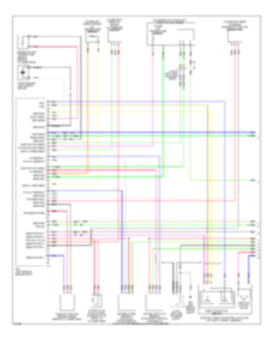
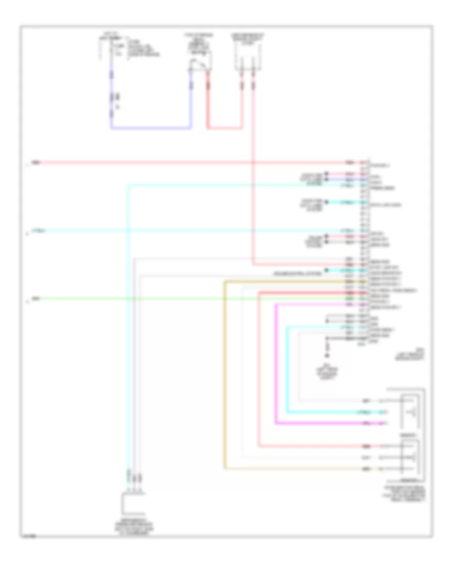
2.0L, Engine Performance Wiring Diagram (1 of 5) for Nissan NV200 S 2013
List of elements for 2.0L, Engine Performance Wiring Diagram (1 of 5) for Nissan NV200 S 2013:
- (lower left side of engine) oil temperature sensor
- (lower right front of engine) oil pressure sensor
- (lower right rear of engine) crankshaft position sensor (pos)
- (on engine air intake duct) mass air flow sensor
- 12b
- 13b
- 14b
- 30b
- 36b
- A/f sensor 1
- Air fuel ratio (a/f) sensor 1 (on exhaust manifold,
- Camshaft position sensor (phase) (rear of cylinder head)
- Ctrl sol valve
- E24 (left rear of engine compt)
- Ecm (left rear of engine compt)
- Electric throttle control actuator (on throttle body assembly)
- Eng oil press sens
- Eng oil temp sens
- Engine coolant temperature sensor (rear of cylinder head)
- F11
- Heated oxygen sensor 2 (in exhaust, downstream of catalytic converter)
- Htd oxy sensor 2
- Intake air temp sens
- Intake air temperature sensor
- Intake valve timing control solenoid valve (front of cylinder head)
- J/c f01 (left side of engine compt)
- Knock sens
- Knock sensor (left side of engine)
- Mass air flow sens
- Pnk
- Pnp sig
- Pos sens (phase)
- Pos sens (pos)
- Press sens
- Red
- Sens gnd
- Sens pwr sply
- Shield
- Temp sens
- Throttle control motor
- Throttle position sensor
- Tps1
- Tps2
- Upstream of catalytic converter)
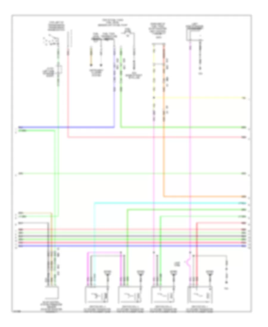
2.0L, Engine Performance Wiring Diagram (2 of 5) for Nissan NV200 S 2013
List of elements for 2.0L, Engine Performance Wiring Diagram (2 of 5) for Nissan NV200 S 2013:
- (forward of fuel tank) evap canister vent control valve
- (left side of engine) condenser
- (top left of transmission) transmission range switch
- (top of fuel tank) fuel level sensor unit & fuel pump
- 16a
- 28b
- 29b
- 35a
- 36a
- 37a
- B19 (base of right "b" pillar)
- B23 m15
- B28 m11
- B29
- B29 m12
- E8 f8
- Evap control system pressure sensor (on evap canister assembly)
- F24
- Fuel level sensor
- Fuel pump
- Fuel tank temperature sensor
- Ignition coil 1 (w/ power transistor) (top of cylinder head)
- Ignition coil 2 (w/ power transistor) (top of cylinder head)
- Ignition coil 3 (w/ power transistor) (top of cylinder head)
- Ignition coil 4 (w/ power transistor) (top of cylinder head)
- Instrument cluster system
- J/c f01 (left side of engine compt)
- Loop wire
- M12
- M69
- Nca
- Pnk
- Red
- Spark plug
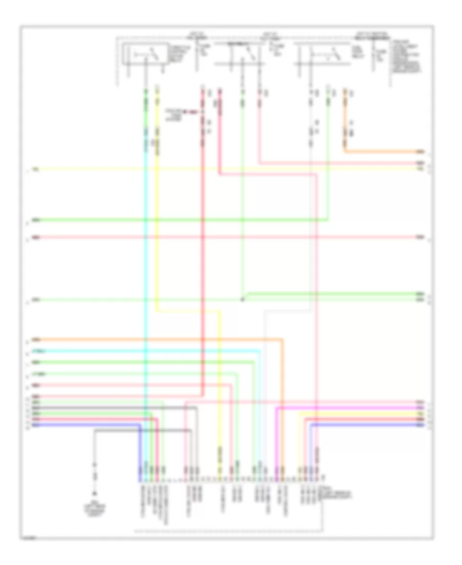
2.0L, Engine Performance Wiring Diagram (3 of 5) for Nissan NV200 S 2013
List of elements for 2.0L, Engine Performance Wiring Diagram (3 of 5) for Nissan NV200 S 2013:
- (or red)
- 24b
- 26a
- 27b
- 33b
- 34b
- A/f sens 1 htr
- Compt)
- Control valve
- Cooling fans system
- Ctrl mtr (close)
- Ctrl mtr (open)
- Ctrl mtr rly
- Ctrl sol valve
- E24 (left rear of engine
- E43
- E45
- E46
- E47
- Ecm (left rear of engine compt)
- Ecm gnd
- Ecm relay
- Ecm rly
- F10
- Fuel inj 1
- Fuel inj 2
- Fuel inj 3
- Fuel inj 4
- Fuel pump relay
- Fuel pump rly
- Fuse 15a
- Fuse 20a
- Hot at all times
- Hot w/ ignition relay energized
- Htd oxy sens 2 htr
- Ign sig 1
- Ign sig 2
- Ign sig 3
- Ign sig 4
- Ipdm e/r (intelligent power distribution module engine room) (left rear of engine compt)
- M69
- Pnk
- Pwr sply
- Red
- Throttle control motor relay
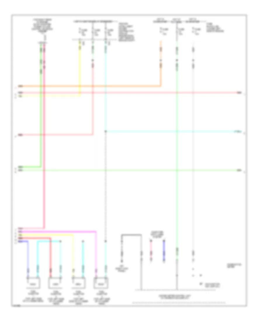
2.0L, Engine Performance Wiring Diagram (4 of 5) for Nissan NV200 S 2013
List of elements for 2.0L, Engine Performance Wiring Diagram (4 of 5) for Nissan NV200 S 2013:
- (top right rear of engine) evap canister purge volume control solenoid valve
- 21b
- Combination meter
- Computer data lines system
- E43
- E45
- Fuel injector (top left side of cylinder head)
- Fuse 10a
- Fuse 15a
- Fuse block (j/b) (lower left side of engine)
- Hot at all times
- Hot in on or start
- Hot w/ ignition relay energized
- Ipdm e/r (intelligent power distribution module engine room) (left rear of engine compt)
- M57 (right kick panel)
- Malfunction ind lamp (mil)
- Pnk
- Red
- Unified meter control unit (w/ information display)
2.0L, Engine Performance Wiring Diagram (5 of 5) for Nissan NV200 S 2013
List of elements for 2.0L, Engine Performance Wiring Diagram (5 of 5) for Nissan NV200 S 2013:
- (center rear of engine compt) j/c e01
- (top of brake pedal assembly) stop lamp switch
- 92a
- Acc pedal poss sens 2
- Accelerator pedal position sensor (top of accelerator pedal assembly)
- Ascd brake sw
- Ascd sw
- Can-h
- Can-l
- Computer data lines system
- Cruise control system
- Data link conn
- E16
- E41 (left rear of engine compt)
- Ecm (left rear of engine compt)
- Fuse 10a
- Fuse block (j/b) (lower left side of engine)
- Gnd
- Hot at all times
- Ign sw
- M69
- Pnk
- Poss sens 1
- Press sens
- Pwr sply
- Red
- Refrigerant pressure sensor (bottom right side of condenser)
- Sens gnd
- Sens pwr sply
- Sensor 1
- Sensor 2
- Stop lamp sw

 Čeština
 Dansk
Dansk Deutsch
 Ελληνικά
 English
 English
 Suomi
Suomi Français
 Français
 עברית
עברית Hrvatski
 Magyar
 Italiano
 日本語
日本語 한국어
한국어 Nederlands
 Polski
 Português
 Português
 Română
 Русский
 Slovenčina
 Slovenščina
 Svenska
 Türkçe
 中文 (中国)