ENGINE PERFORMANCE
2.3L
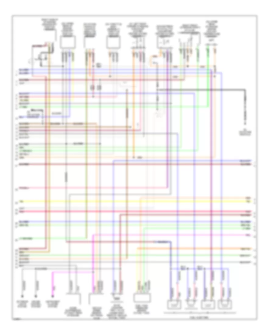
2.3L, Engine Performance Wiring Diagram (1 of 3) for Suzuki Aerio S 2005
 https://portal-diagnostov.com/license.html
Automotive Electricians Portal FZCO
Automotive Electricians Portal FZCO
https://portal-diagnostov.com/license.html
https://portal-diagnostov.com/license.html
Automotive Electricians Portal FZCO
Automotive Electricians Portal FZCO
List of elements for 2.3L, Engine Performance Wiring Diagram (1 of 3) for Suzuki Aerio S 2005:
- (pin 7-10 not used)
- Air conditioning & transmissions systems
- Air conditioning system
- C45
- C46
- Egr stepper motor (left rear of engine)
- Engine control module (behind glove box)
- Evap canister purge valve (at rear of engine, near egr stepper motor)
- Fuel pump & gauge (in fuel tank)
- Fuel pump relay (on relay box)
- Fuse 15a
- G20 (near right side of fuel tank)
- G3 (on intake manifold)
- G4 (on intake manifold)
- Hot at all times
- Hot in run or start
- Isc valve (right rear of engine compt)
- Junction/ fuse box
- Knock sensor (at right side of engine)
- Main fuse box (on left side of engine compt)
- Main relay (on relay box)
- Pnk
- Power steering pump pressure switch (on power steering pump)
- Red
- Starting/ charging system
2.3L, Engine Performance Wiring Diagram (2 of 3) for Suzuki Aerio S 2005
List of elements for 2.3L, Engine Performance Wiring Diagram (2 of 3) for Suzuki Aerio S 2005:
- (at left front corner of engine, in exhaust system) heated oxygen sensor 1
- (downstream of catalytic converter) heated oxygen sensor 2
- (on intake manifold)
- (on intake manifold) manifold absolute pressure sensor
- (on throttle body assembly) throttle position sensor
- (on upper rear of engine) camshaft position sensor
- (on upper rear of engine) engine coolant temperature sensor
- (right front of engine compt) iat & air airflow meter
- (right side of of engine) crankshaft position sensor
- Cruise control system
- Evap canister vent valve (under right rear of vehicle, on fuel tank)
- Exterior lights system
- Fuel injectors
- Fuel tank pressure sensor (in fuel tank)
- G3 (on intake manifold)
- Instrument cluster system
- Nca
- Noise suppressor (at right rear of engine)
- Pnk
- Vehicle speed sensor (on trans- axle)
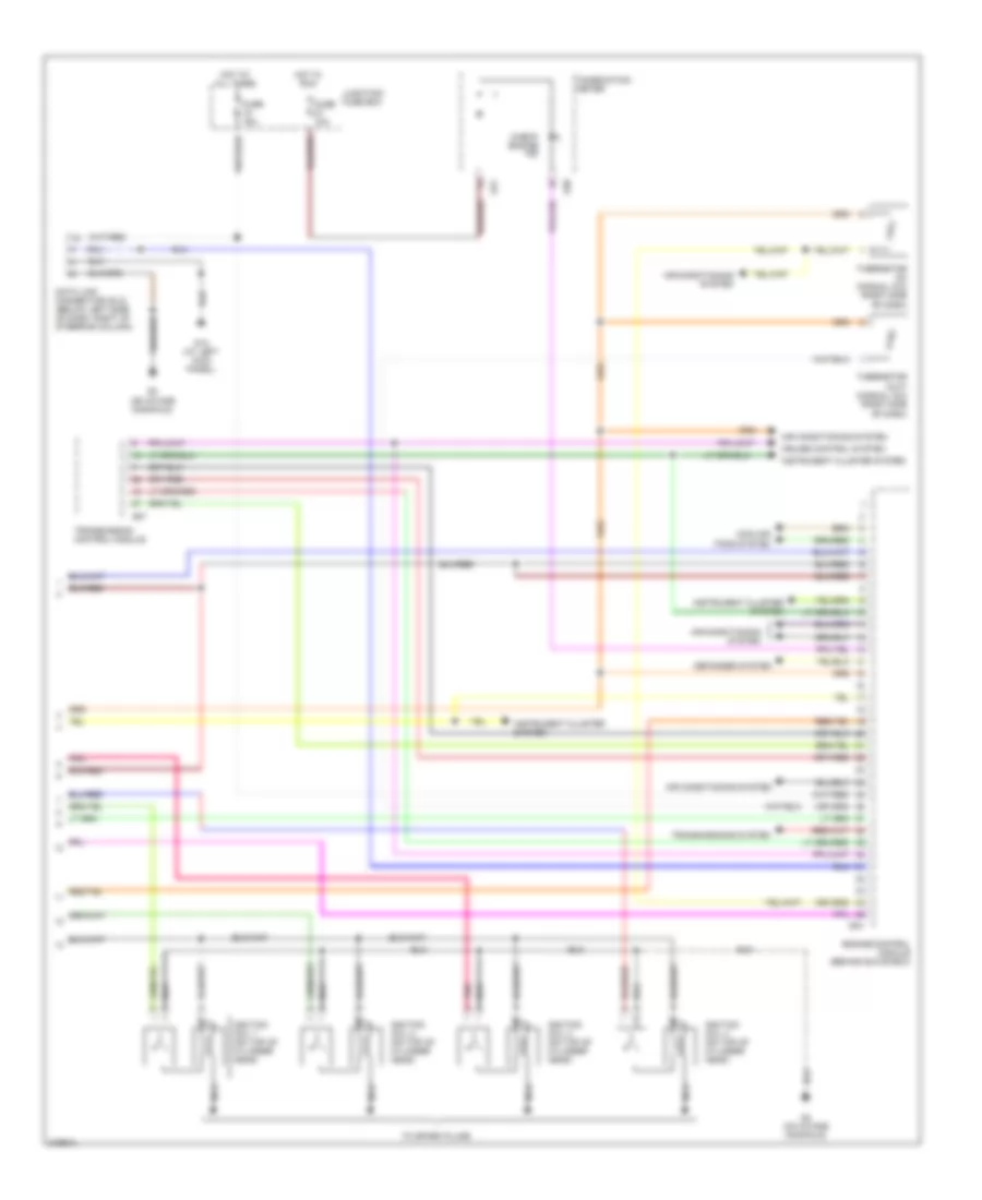
2.3L, Engine Performance Wiring Diagram (3 of 3) for Suzuki Aerio S 2005
List of elements for 2.3L, Engine Performance Wiring Diagram (3 of 3) for Suzuki Aerio S 2005:
- Air conditioning system
- Check engine ind
- Combination meter
- Cooling fans system
- Cruise control system
- Data link connector (dlc) (below left side of dash, right of steering column)
- Defogger system
- Engine control module (behind glove box)
- Fuse 10a
- Fuse 15a
- G04
- G07
- G13 (at left kick panel)
- G20
- G21
- G3 (on intake manifold)
- G4 (on intake manifold)
- Hot at all times
- Hot in run
- Ignition coil 1 (on top of cylinder head)
- Ignition coil 2 (on top of cylinder head)
- Ignition coil 3 (on top of cylinder head)
- Ignition coil 4 (on top of cylinder head)
- Instrument cluster system
- Junction/ fuse box
- Nca
- Pnk
- Thermistor (in) (manual a/c) (right side of dash)
- Thermistor (out) (manual a/c) (right side of dash)
- To spark plugs
- Transmission control module
- Transmissions system

 Čeština
 Dansk
Dansk Deutsch
 Ελληνικά
 English
 English
 Suomi
Suomi Français
 Français
 עברית
עברית Hrvatski
 Magyar
 Italiano
 日本語
日本語 한국어
한국어 Nederlands
 Polski
 Português
 Português
 Română
 Русский
 Slovenčina
 Slovenščina
 Svenska
 Türkçe
 中文 (中国)