POWER DISTRIBUTION
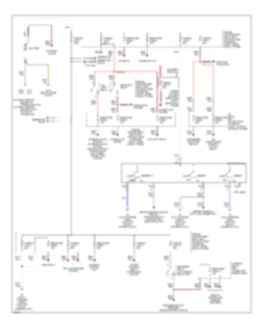
Power Distribution Wiring Diagram (1 of 2) for Mitsubishi 3000GT VR-4 1998
List of elements for Power Distribution Wiring Diagram (1 of 2) for Mitsubishi 3000GT VR-4 1998:
- (a/t-right rear of
- (convert- ible only)
- (diagram 2 of 2)
- (m/t-right rear of
- (not used)
- A/c relay box (on left side of engine compt, in front of shock tower)
- Acc
- Air conditioning magnetic clutch relay
- Anti-lock brakes system
- Battery
- Combination meter
- Condenser fan motor relays
- Dedicated fuse 1 20a
- Dedicated fuse 1o 10a
- Dedicated fuse 2 15a
- Dedicated fuse 3 10a
- Dedicated fuse 4 15a
- Dedicated fuse 5 10a
- Dedicated fuse 6 10a
- Dedicated fuse 7 20a
- Dedicated fuse 8 20a
- Dedicated fuse 9 10a
- Defogger relay (on interior relay box)
- Defogger switch, defogger, engine control module
- Engine compartment relay box (on right side of engine compt, near shock tower)
- Engine compt, on top of transaxle)
- Engine control module, srs ecu, starter relay & park/neutral position switch
- Engine, on transaxle stud)
- Fog light relay
- Fusible link 1 120a
- Fusible link 10 40a
- Fusible link 12 80a
- Fusible link 3 40a
- Fusible link 4 30a
- Fusible link 5 40a
- Fusible link 6 40a
- Fusible link 7 60a
- Fusible link 9 30a
- Fusible link box (on right side of eng compt, near shock tower)
- G117 (m/t)
- G123 (below wiper motor)
- G129 (a/t)
- Generator
- Generator (dohc)
- Generator (sohc)
- Generator relay, data link connector 1
- Hazard switch
- Headlight relay
- Headlights system
- Horn relay
- Ignition switch
- Interior lights system, exterior lights system, engine controls system (dohc non turbo), power tops system
- Interior relay box (under left side of dash)
- Lock
- Mfi relay
- Nca
- Power tops system
- Power windows relay, power seat switch
- Radiator fan motor
- Red
- Remote controlled mirrors (heaters)
- Start
- Starter motor
- Sunroof control unit
- Tail light relay
- To multi- purpose fuse 6 (junction block)
- To multi-purpose fuse 18 (junction block) (diagram 2 of 2)
- To multi-purpose fuse 3 (junction block) (diagram 2 of 2)
- To multi-purpose fuse 4 (junction block) (diagram 2 of 2)
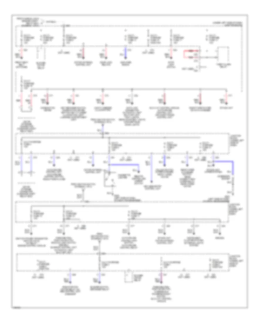
Power Distribution Wiring Diagram (2 of 2) for Mitsubishi 3000GT VR-4 1998
List of elements for Power Distribution Wiring Diagram (2 of 2) for Mitsubishi 3000GT VR-4 1998:
- (not used)
- (under left side of dash) junction block
- Accessory socket
- Amplifier (radio)
- Auto-cruise control main switch, auto-cruise control relay
- Auto-cruise control unit, auto-cruise control switch, radio/tape player
- Blower motor relay
- Blower switch, defogger relay
- C68
- C69
- C70
- C71
- C74
- C77
- C78
- C80
- C81
- C82
- C83
- Cigarette lighter
- Column switch (wiper/washer), front wper motor
- Combination meter
- Data link connector, automatic light shut-off unit, foot lights, rear courtesy lights (convertible), door lights
- Door lock relays
- Elc-4 a/t control module, auto-cruise control unit, air conditioning control unit
- Etacs unit
- Etacs unit (wiper system)
- Etacs unit, motor antenna control unit
- From fusible link 6 (engine compt. relay box) (diagram 1 of 2)
- From ignition switch (diagram 1 of 2)
- Front seat belt switches
- G202 (left side of dash, on deck crossmember)
- Ignition power transistor, ignition coils, mfi relay, engine control module
- Instrument cluster system, exterior lights system
- Iod or storage connector (in engine compt relay box)
- Junction block (under left side of dash)
- Key reminder switch, combination meter, ignition key cylinder illumination light, luggage compartment light
- Keyless entry control unit
- Motor antenna control unit
- Multi- purpose fuse 1 10a
- Multi- purpose fuse 10 15a
- Multi- purpose fuse 11 15a
- Multi- purpose fuse 12 10a
- Multi- purpose fuse 13 15a
- Multi- purpose fuse 14 10a
- Multi- purpose fuse 15 position
- Multi- purpose fuse 16 30a
- Multi- purpose fuse 17 15a
- Multi- purpose fuse 18 10a
- Multi- purpose fuse 19 10a
- Multi- purpose fuse 2 position
- Multi- purpose fuse 5 15a
- Multi- purpose fuse 6 10a
- Multi- purpose fuse 8 position
- Multi- purpose fuse 9 15a
- Multi-purpose fuse 3 10a
- Multi-purpose fuse 4 10a
- Multi-purpose fuse 7 10a
- Park/neutral position switch, backup light switch, srs ecu, sunroof control unit, automatic light shut-off unit
- Park/neutral postion switch, overdrive & power/economy switch, elc-4 a/t control module
- Radiator fan motor relay (hi), abs control unit, g-sensor
- Radio/tape player, cd auto changer
- Rear wiper & washer switch, rear intermittent wiper relay, rear wiper motor
- Red
- Red/ yel
- Remote controlled mirror switch
- Srs ecu
- Stop light switch
- Theft-alarm relay
- Vanity mirrors (illumination)

 Čeština
 Dansk
Dansk Deutsch
 Ελληνικά
 English
 English
 Suomi
Suomi Français
 Français
 עברית
עברית Hrvatski
 Magyar
 Italiano
 日本語
日本語 한국어
한국어 Nederlands
 Polski
 Português
 Português
 Română
 Русский
 Slovenčina
 Slovenščina
 Svenska
 Türkçe
 中文 (中国)