SHIFT INTERLOCKS
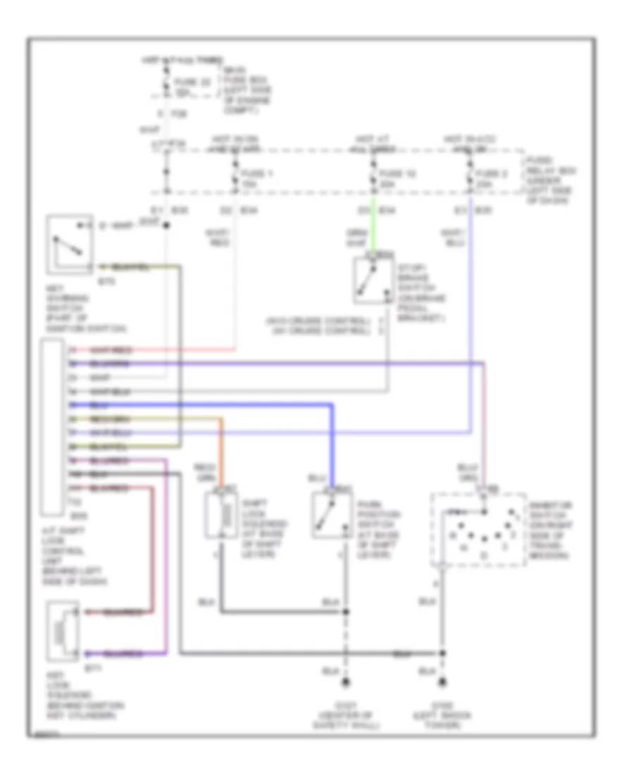
Shift Interlock Wiring Diagram for Subaru Impreza Brighton 1996
List of elements for Shift Interlock Wiring Diagram for Subaru Impreza Brighton 1996:
- (w/o cruise control) (w/ cruise control)
- A/t shift lock control unit (behind left side of dash)
- B34 d2
- B34 d3
- B35 e3
- B55
- B64
- B70
- B71
- F28
- F34 a7
- Fuse 1 15a
- Fuse 12 20a
- Fuse 2 20a
- Fuse 22 15a
- Fuse/ relay box (under left side of dash)
- G102 (left shock tower)
- G121 (center of safety wall)
- Hot at all times
- Hot in acc and on
- Hot in on and start
- Inhbitor switch (on right side of trans- mission)
- Key lock solenoid (behind ignition key cylinder)
- Key warning switch (part of ignition switch)
- Main fuse box (left side of engine compt)
- Park position switch (at base of shift lever)
- R41
- Shift lock solenoid (at base of shift lever)
- Stop/ brake switch (on brake pedal bracket)
 Čeština
 Dansk
Dansk Deutsch
 Ελληνικά
 English
 English
 Suomi
Suomi Français
 Français
 עברית
עברית Hrvatski
 Magyar
 Italiano
 日本語
日本語 한국어
한국어 Nederlands
 Polski
 Português
 Português
 Română
 Русский
 Slovenčina
 Slovenščina
 Svenska
 Türkçe
 中文 (中国)
 Español