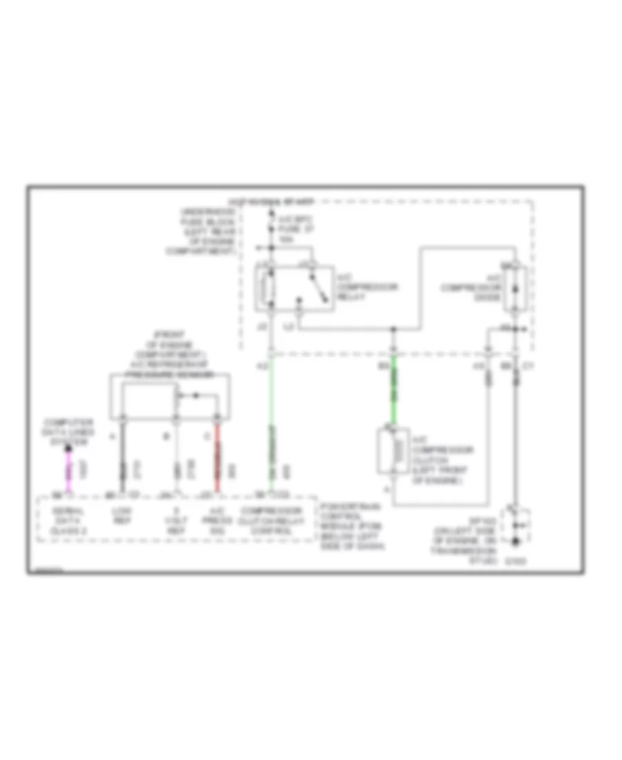
AIR CONDITIONING
Compressor Wiring Diagram for Pontiac Grand Am SC/T 2005
List of elements for Compressor Wiring Diagram for Pontiac Grand Am SC/T 2005:
- (front of engine compartment) a/c refrigerant pressure sensor
- A/c bfc fuse 37 10a
- A/c compressor clutch (left front of engine)
- A/c compressor diode
- A/c compressor relay
- A/c press sig
- Compressor clutch relay control
- Computer data lines system
- G103
- Hot in on & start
- Low ref
- Powertrain control module (pcm) (below left side of dash)
- Serial data class 2
- Sp103 (on left side of engine, on transmission stud)
- Underhood fuse block (left rear of engine compartment)
- Volt ref
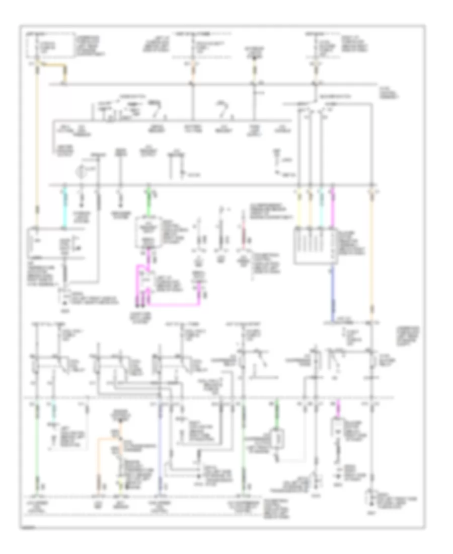
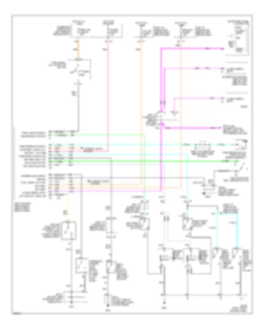
Manual A/C Wiring Diagram for Pontiac Grand Am SC/T 2005
List of elements for Manual A/C Wiring Diagram for Pontiac Grand Am SC/T 2005:
- A/c
- A/c bfc fuse 37 10a
- A/c com- pressor
- A/c compressor clutch (left front of engine)
- A/c compressor clutch relay control
- A/c compressor diode
- A/c compressor relay
- A/c disable
- A/c on
- A/c press sig
- A/c refrigerant pressure sensor (front of engine compartment)
- A/c request
- A/c request input
- A/c request output
- A10
- A11
- Air temperature actuator (behind dash, right side of hvac assembly)
- B10
- Battery voltage
- Bi- lvl
- Blower motor (below right side of dash)
- Blower motor resistor assembly (below right side of dash)
- Blower switch
- Body control module (bcm) (below right side of dash)
- C1 a5
- C1 b11
- C10
- C11
- Computer data lines system
- Cool fan 1 fuse 8 30a
- Cool fan 1 relay
- Cool fan 2 fuse 52 15a
- Cool fan 2 ground fuse 55 30a
- Cool fan 2 relay
- Cool fan mode relay
- Def
- Def on
- Defog
- Defog request
- Defogger system
- Door ctrl input
- E10
- Ect sensor
- Engine controls system
- Engine coolant temperature (ect) sensor (on top left rear of engine)
- Exterior lights system
- G10
- G103
- G201
- G202
- G203
- Gnd
- Ground
- Heat
- Heat/ def
- Heater command output
- Hi blo mot fuse 53 30a
- High
- High speed fan control
- Hot at all times
- Hot in on
- Hot in on & start
- Htr-a/c fuse 46 10a
- Hvac blower fuse d 20a
- Hvac blower relay
- Hvac control assembly
- Ign
- Ign 3 voltage
- Illum
- Interior lights system
- Ipc/hvac batt fuse l 10a
- K10
- L10
- Left cooling fan (behind left side of radiator)
- Left i/p fuse block (behind left side of dash)
- Logic
- Low
- Low ref
- Low speed fan control
- M10
- Max
- Mode switch
- Off
- Powertrain control module (pcm) (below left side of dash)
- Rear defog
- Right cooling fan (behind right side of radiator)
- Right i/p fuse block (behind right side of dash)
- S102 (in transmission harness)
- Serial data class 2
- Sp103 (on left side of engine, on transmission stud)
- Sp201 (on left front side of dash, near fuse block)
- Sp202 (on left front side of dash, near fuse block)
- Sp203 (right front side of dash)
- Tan
- Underhood fuse block (left rear of engine compartment)
- Underhood fuse block (left rear of engine compt)
- Vent
- Volt ref
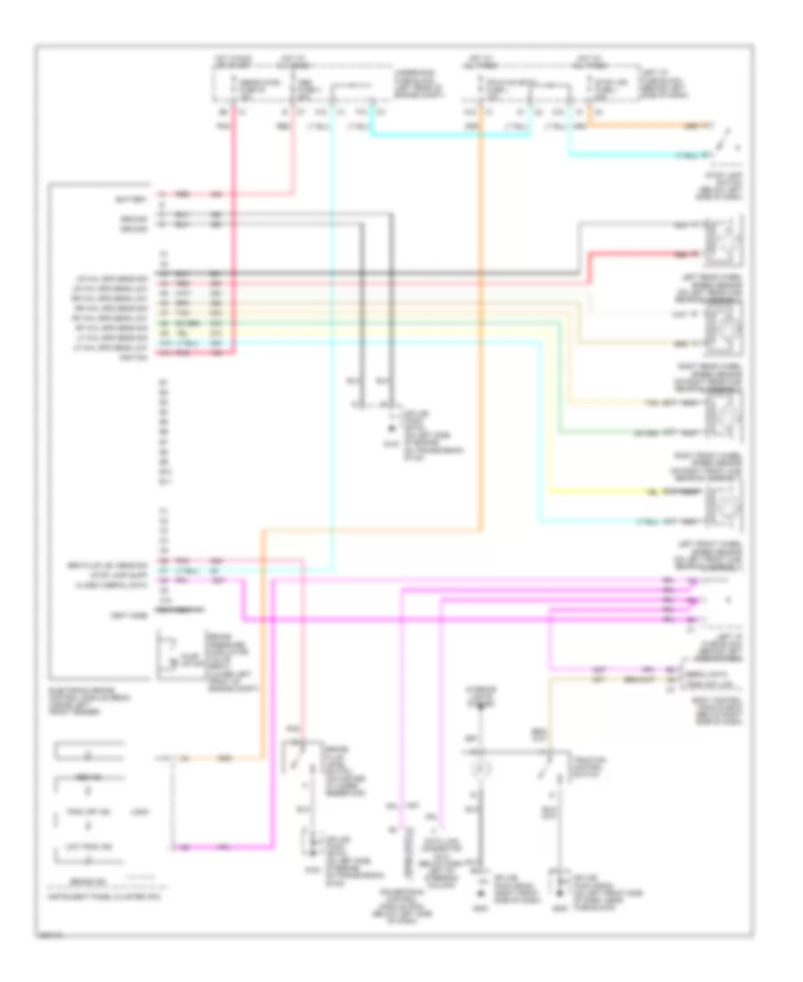
ANTI-LOCK BRAKES
Anti-lock Brakes Wiring Diagram for Pontiac Grand Am SC/T 2005
List of elements for Anti-lock Brakes Wiring Diagram for Pontiac Grand Am SC/T 2005:
- A10
- A11
- A12
- Abs fuse 4 50a
- Abs ind
- Abs/evo/ign fuse 40 15a
- B10
- B11
- Battery
- Body control module (bcm) (below right side of dash)
- Brake fluid level switch (on master cylinder reservoir)
- Brake ind
- Brake pressure modulator valve (bpmv) (lower left front of engine compt)
- Brk fluid lev sens sig
- C10
- C11
- Class 2 serial data
- Data link connector (dlc) (below dash, left of steering column)
- Electronic brake control module (ebcm) (inside left front fender)
- F12
- G103
- G202
- G203
- Ground
- Hot at all times
- Hot in run or start
- Ignition
- Instrument panel cluster (ipc)
- Interior lights system
- Ipc/hvac batt fuse l 10a
- Left front wheel speed sensor (on left front hub/ bearing assembly)
- Left i/p fuse block (behind left side of dash)
- Left rear wheel speed sensor (on left rear hub/ bearing assembly)
- Lf whl spd sens low
- Lf whl spd sens sig
- Logic
- Low trac ind
- Lr whl spd sens low
- Lr whl spd sens sig
- Nca
- Pnk
- Powertrain control module (pcm) (below left side of dash)
- Pump motor
- Red
- Rf whl spd sens low
- Rf whl spd sens sig
- Right front wheel speed sensor (on right front hub/ bearing assembly)
- Right rear wheel speed sensor (on right rear hub/ bearing assembly)
- Rr whl spd sens low
- Rr whl spd sens sig
- Serial data
- Splice pack sp103 (on left side of engine, on transmission stud)
- Splice pack sp202 (on left front side of dash, near fuse block)
- Splice pack sp203 (right front side of dash)
- Stop lamp supp
- Stop lamp switch (below left side of dash)
- Stop lps fuse j 20a
- Tan
- Trac cntl sw
- Trac off ind
- Traction control switch
- Underhood fuse block (left rear of engine compt)
- Vent hose
ANTI-THEFT
Anti-theft Wiring Diagram for Pontiac Grand Am SC/T 2005
List of elements for Anti-theft Wiring Diagram for Pontiac Grand Am SC/T 2005:
- (below dash, left of steering column)
- (left ``b" pillar)
- A/c-bfc fuse 37 10a
- A10
- B10
- B11
- Battery + voltage
- Bfc battery fuse f 10a
- Body control module (bcm) (below right side of dash)
- C1 f3
- C11
- Class 2 serial data
- Data
- Data link connector (dlc)
- Door lock switch
- Dr lock/unlock sig
- Driver door lock switch
- Front passenger
- G202
- G301
- G302
- Gnd
- Ground
- Headlamp rly ctrl
- Headlights system
- Horn relay ctrl
- Horns system
- Hot at all times
- Hot in acc, on or start
- Hot in on or start
- Ign
- Ignition 0 voltage
- Ignition 1 voltage
- Ignition lock cylinder
- Instrument panel cluster (ipc)
- Ipc/bfc acc fuse i 10a
- Left front door jamb switch
- Left i/p fuse block (behind left side of dash)
- Left rear door ajar switch (sedan)
- Lf door sw sig
- Logic
- Passlock sensor
- Pnk
- Power distribution system
- Powertrain control module (pcm) (below left side of dash)
- Rear compartment lid release switch
- Remote control door lock receiver (rcdlr) (on rear package shelf)
- Rf door sw sig
- Right front door jamb switch
- Right i/p fuse block (behind right side of dash)
- Right rear door ajar switch (sedan)
- Sec sensor lo ref
- Security ind
- Security sensor sig
- Sp202 (on left front side of dash, near fuse block)
- Sp301 (on left side of passenger compt, at kick panel)
- Sp302 (right front rocker panel)
- Trunk release relay
- Trunk rly ctrl
- Trunk switch sig
- Underhood fuse block (left rear of engine compt)
BODY CONTROL MODULES
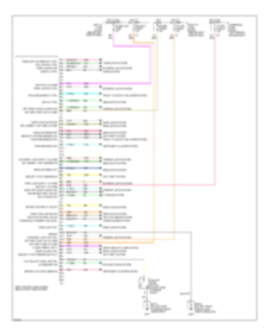
Body Control Modules Wiring Diagram for Pontiac Grand Am SC/T 2005
List of elements for Body Control Modules Wiring Diagram for Pontiac Grand Am SC/T 2005:
- A/c bfc fuse 37 10a
- A/c request sig
- A10
- A11
- A12
- A2 c1
- Air conditioning system
- Anti-lock brake system
- Anti-theft system
- B10
- B11
- B12
- Battery fuse voltage
- Battery positive voltage
- Bfc batt fuse f 10a
- Body control module (bcm) (below right side of dash)
- Brake fluid level sens sig
- Class 2 serial data
- Computer data lines system
- Coolant level switch (in right side of engine compt)
- Courtesy lamp low ctrl
- Cruise fuse e 10a
- Door lock ctrl
- Door lock/unlock sig
- Door locks system
- Door unlock ctrl
- Driver lock relay unlock
- Driver seat belt sw sig
- Drl ambient light sen low ref
- Drl ambient light sensor sig
- Drl rly ctrl
- Exterior lights system
- Fog lamp rly ctrl
- Front fog lamp sw sig
- G101
- G202
- Ground
- Headlamp beam-high
- Headlamp beam-low
- Headlamp low beam rly ctrl
- Headlights system
- Horn rly ctrl
- Horns system
- Hot at all times
- Hot in acc, on or start
- Hot in on
- Hot in on or start
- Ignition 0 voltage
- Ignition 1 voltage
- Instrument cluster system
- Int lps fuse g 10a
- Interior lights system
- Ipc/bfc acc fuse i 10a
- Key-in ign sw sig
- Left front door ajar sw sig
- Left i/p fuse block (behind left side of dash)
- Low coolant level ind ctrl
- Park brake sw sig
- Park lamp rly ctrl
- Park lamp sw sig
- Pnk
- Right frt door ajar sw sig
- Right i/p fuse block (behind right side of dash)
- Security syst sensor sig
- Security syst sensor sup volt
- Security system sensor low
- Sp101 (on left side of engine compt, near strut)
- Sp202 (on left front side of dash, near fuse block)
- Traction control sw sig
- Trunk release rly ctrl
- Trunk release sw sig
- Trunk, tailgate, fuel doors system
- Underhood fuse block (left rear of engine compt)
- Warning system
- Windshield washer fluid level
- Wiper/washer system
COMPUTER DATA LINES
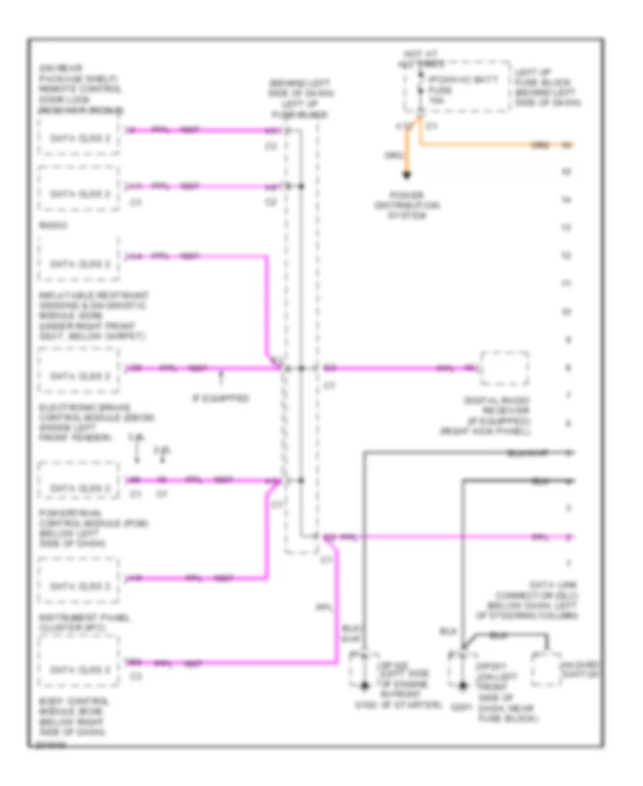
Computer Data Lines Wiring Diagram for Pontiac Grand Am SC/T 2005
List of elements for Computer Data Lines Wiring Diagram for Pontiac Grand Am SC/T 2005:
- (behind left side of dash) left i/p fuse block
- (on rear package shelf) remote control door lock receiver (rcdlr)
- 2.2l
- 3.4l
- A12
- Body control module (bcm) (below right side of dash)
- Data clss 2
- Data link connector (dlc) (below dash, left of steering column)
- Digital radio receiver (if equipped) (right kick panel)
- Electronic brake control module (ebcm) (inside left front fender)
- G201
- Hazard switch
- Hot at all times
- If equipped
- Inflatable restraint sensing & diagnostic module (sdm) (under right front seat, below carpet)
- Instrument panel cluster (ipc)
- Ipc/hvac batt fuse 10a
- Left i/p fuse block (behind left side of dash)
- Power distribution system
- Powertrain control module (pcm) (below left side of dash)
- Radio
- Sp102 (left side of engine, in front g102 of starter)
- Sp201 (on left front side of dash, near fuse block)
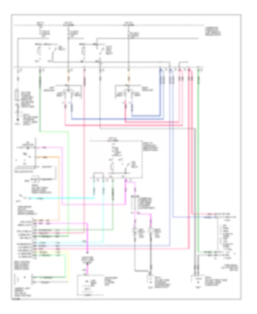
COOLING FAN
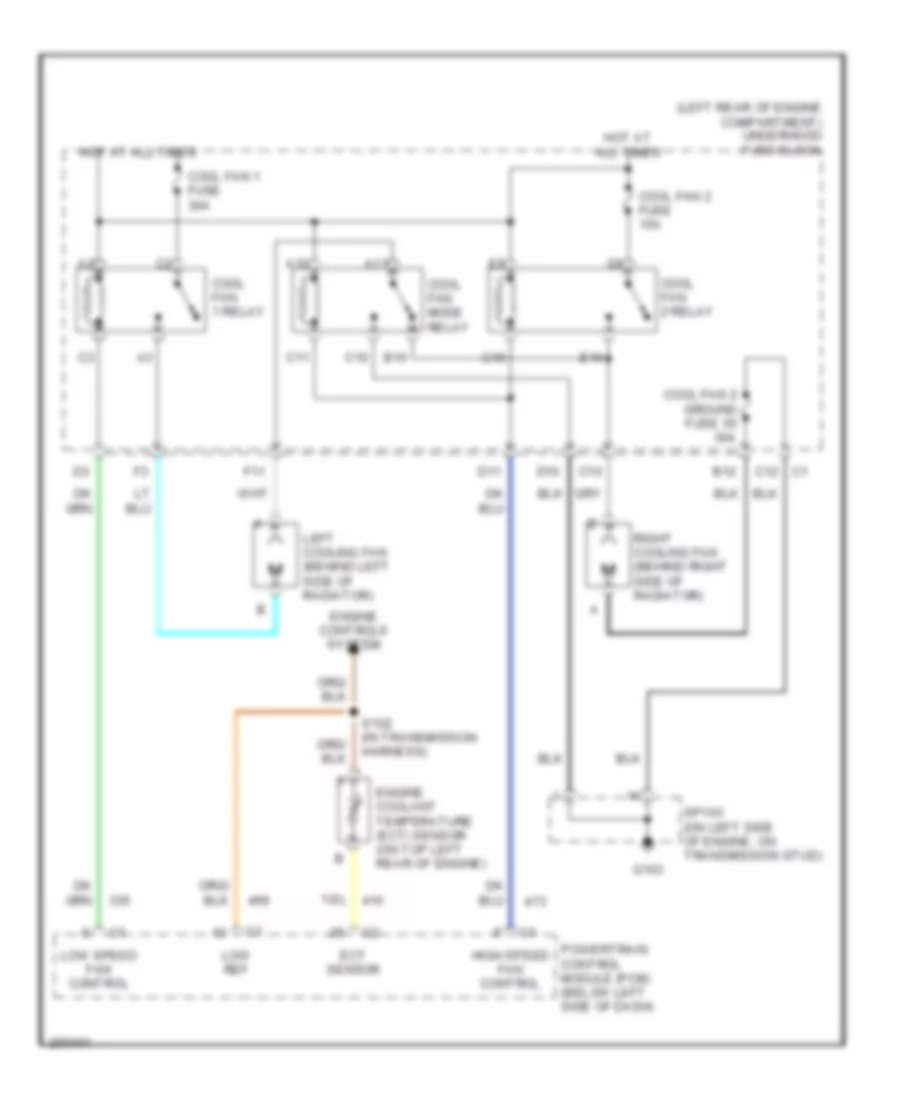
Cooling Fan Wiring Diagram for Pontiac Grand Am SC/T 2005
List of elements for Cooling Fan Wiring Diagram for Pontiac Grand Am SC/T 2005:
- (left rear of engine compartment) underhood fuse block
- A10
- A11
- B10
- B12
- C10
- C11
- C12
- Cool fan 1 fuse 30a
- Cool fan 1 relay
- Cool fan 2 fuse 15a
- Cool fan 2 ground fuse 55 30a
- Cool fan 2 relay
- Cool fan mode relay
- D10
- D11
- E10
- Ect sensor
- Engine controls system
- Engine coolant temperature (ect) sensor (on top left rear of engine)
- F11
- G10
- G103
- High speed fan control
- Hot at all times
- Left cooling fan (behind left side of radiator)
- Low ref
- Low speed fan control
- Powertrain control module (pcm) (below left side of dash)
- Right cooling fan (behind right side of radiator)
- S102 (in transmission harness)
- Sp103 (on left side of engine, on transmission stud)
CRUISE CONTROL
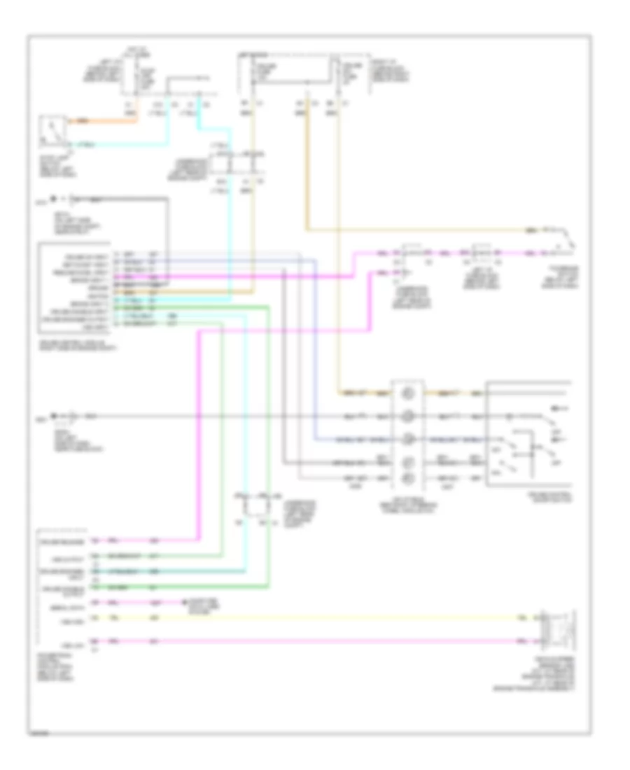
Cruise Control Wiring Diagram for Pontiac Grand Am SC/T 2005
List of elements for Cruise Control Wiring Diagram for Pontiac Grand Am SC/T 2005:
- A12
- B12
- B4 c1
- Brake input 1
- Brake input 2
- C206
- C207
- Computer data lines system
- Cruise control module (right side of engine compt)
- Cruise control on/off switch
- Cruise disable input
- Cruise disable output
- Cruise engaged input
- Cruise engaged output
- Cruise fuse 10a
- Cruise on input
- Cruise release
- Cruise sw fuse 2a
- F12
- G101
- G201
- Ground
- Hot at all times
- Hot in run
- Ignition
- Inflatable restraint steering wheel module coil
- Left i/p fuse block (behind left side of dash)
- Off
- Powertrain control module (pcm) (below left side of dash)
- R/a
- Resume/accel input
- Right i/p fuse block (behind right side of dash)
- S/c
- Serial data
- Set/coast input
- Sp101 (on left side of engine compt, near strut)
- Sp201 (on left side of dash, near fuse block)
- Stop lamp switch (below left side of dash)
- Stop lps fuse 20a
- Tcc/brake switch (below left side of dash)
- Underhood fuse block (left rear of engine compt)
- Vehicle speed sensor (vss) (m/t: at rear of engine/transaxle) (a/t: at rear of engine/transaxle assembly)
- Vss high
- Vss input
- Vss low
- Vss output
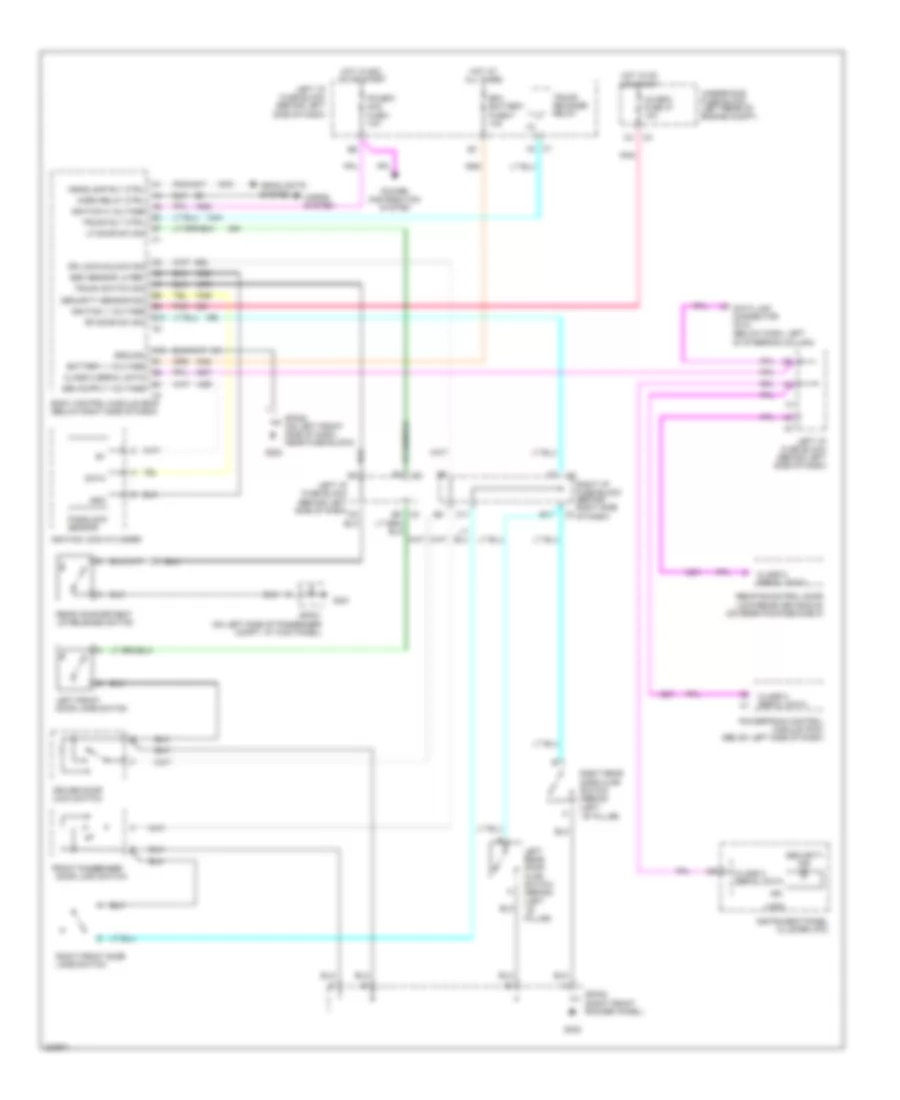
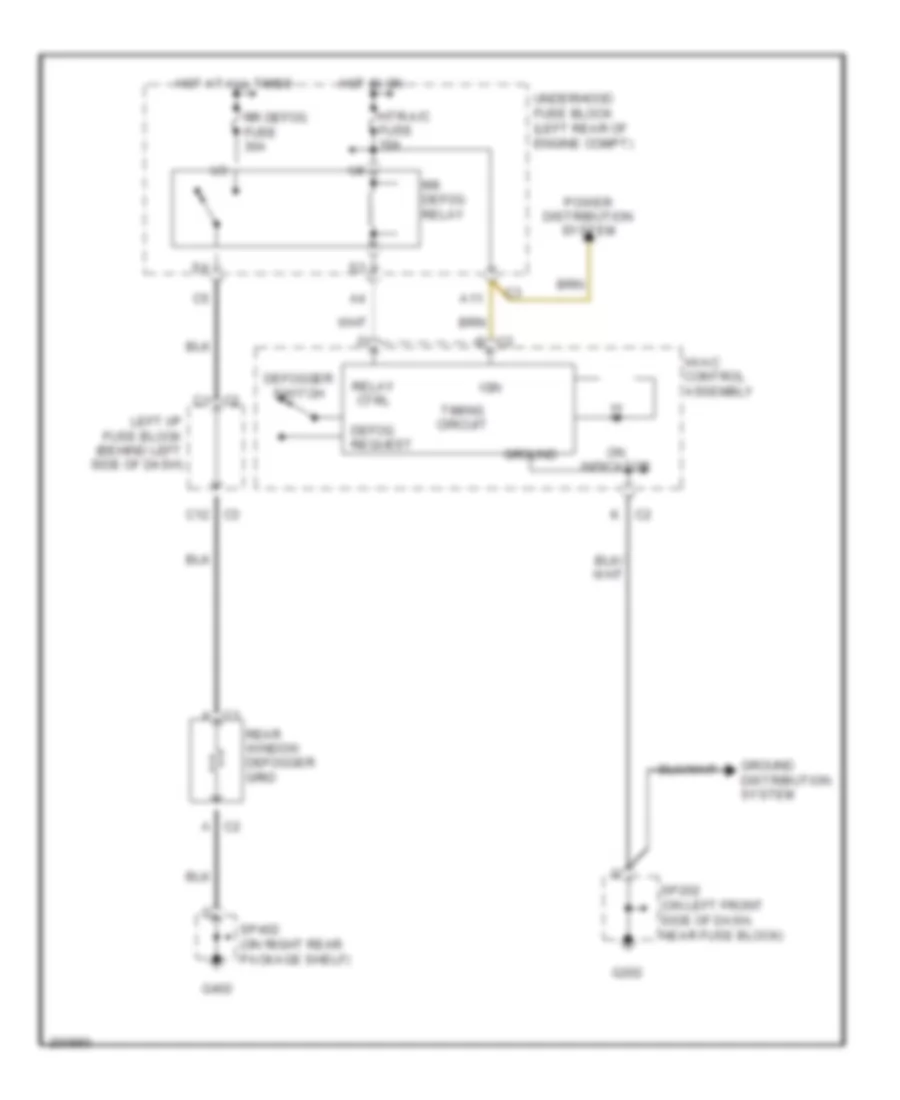
DEFOGGERS
Defoggers Wiring Diagram for Pontiac Grand Am SC/T 2005
List of elements for Defoggers Wiring Diagram for Pontiac Grand Am SC/T 2005:
- A11
- C c2
- C1 a
- C1 c2
- C2 a
- C3 c12
- Defog request
- Defogger switch
- G202
- G402
- Ground
- Ground distribution system
- Hot at all times
- Hot in on
- Htr-a/c fuse 10a
- Hvac control assembly
- Ign
- K c2
- Left i/p fuse block (behind left side of dash)
- On indicator
- Power distribution system
- Rear window defogger grid
- Relay ctrl
- Rr defog fuse 30a
- Rr defog relay
- Sp202 (on left front side of dash, near fuse block)
- Sp402 (on right rear package shelf)
- Timing circuit
- Underhood fuse block (left rear of engine compt)
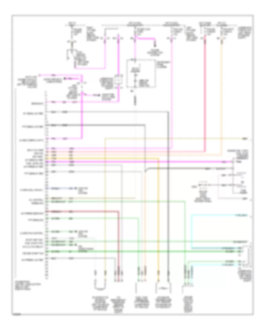
ENGINE PERFORMANCE
2.2L VIN F
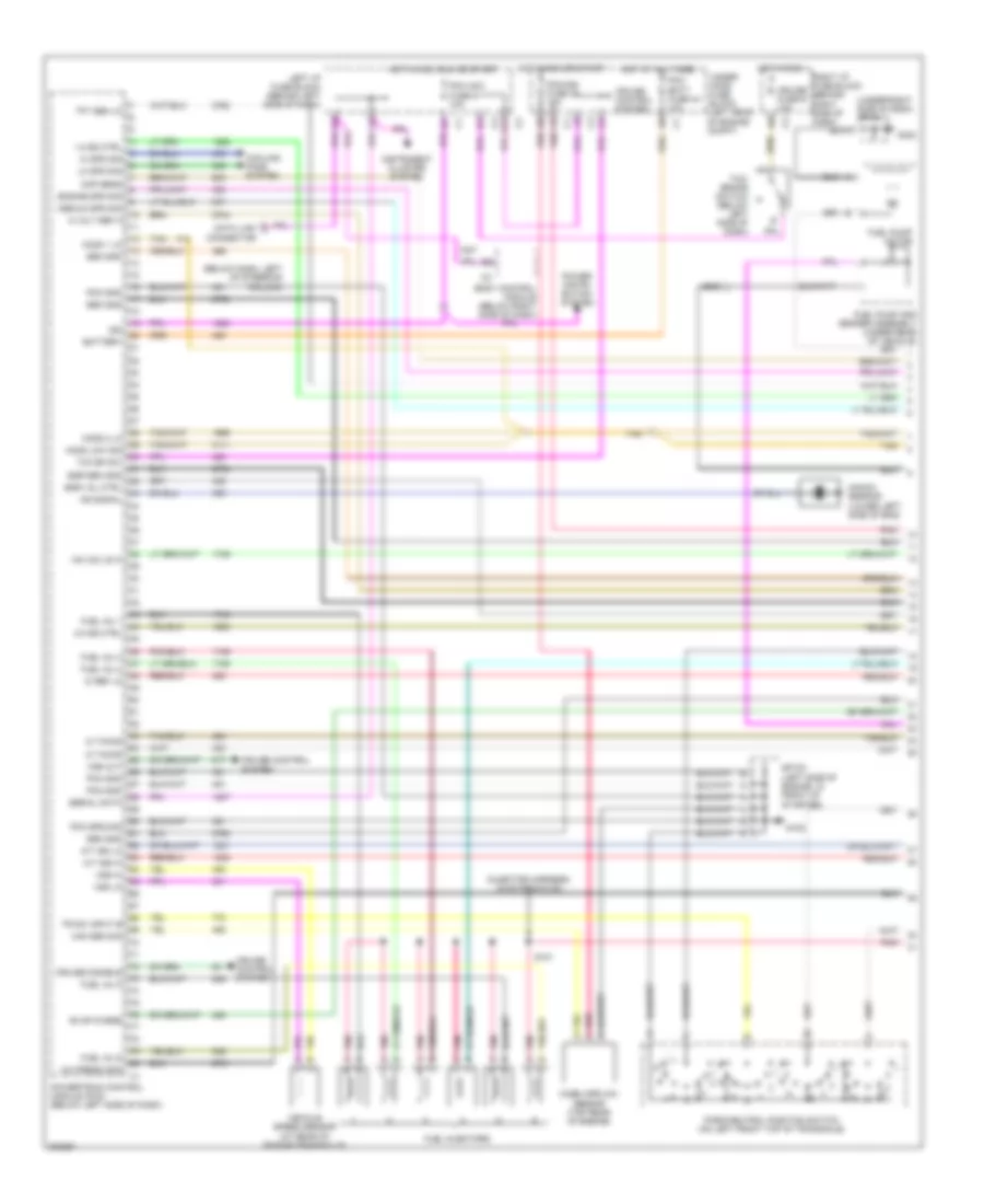
2.2L VIN F, Engine Performance Wiring Diagram (1 of 3) for Pontiac Grand Am SC/T 2005
List of elements for 2.2L VIN F, Engine Performance Wiring Diagram (1 of 3) for Pontiac Grand Am SC/T 2005:
- (a/t)
- (inside fuel tank) fuel pump & sender assembly
- A/c clutch relay
- A/c press 5v ref
- A/c press low ref
- A/c press sens sig
- A/c refrigerant pressure sensor (front of engine compt)
- Air conditioning system
- B12
- Battery
- Brake sw
- C8 pnk
- Class 2 serial data
- Computer data lines system
- Cooling fan system
- Cruise control module (right side of engine compt)
- Cruise fuse e 10a
- Cruise inhibit sig
- Data link connector (dlc) (below dash, left of steering column)
- Evap vent sol
- Evaporative emission canister vent solenoid (under rear of vehicle)
- Ftp sens 5v ref
- Ftp sens low ref
- Ftp sens sig
- Fuel level sig
- Fuel pump
- Fuel pump ctrl
- Fuel tank pressure (ftp) sensor (under rear of vehicle)
- G302
- Hi spd cool fan rly
- Hot at all times
- Hot in acc, run or start
- Hot in run
- Hot in run or start
- Iat sens 5v ref
- Iat sens low ref
- Ign 0 voltage
- Ignition
- Instrument panel cluster
- Intake air temperature (iat) sensor (on engine air intake duct)
- Ipc/bfc acc fuse i 10a
- Left i/p fuse block (behind left side of dash)
- Lo spd fan control
- Mil control
- Pcm acc fuse g 10a
- Pcm batt fuse 44 10a
- Pcm ign fuse 39 10a
- Pnk
- Power distribution system
- Powertrain control module (pcm) (below left side of dash)
- Right i/p fuse block (behind right side of dash)
- Service engine soon ind
- Solid state
- Speed sig
- Splice pack sp302 (right front rocker panel)
- Tan
- Tcc/ brake switch (below left side of dash)
- Underhood fuse block (left rear of engine compt)
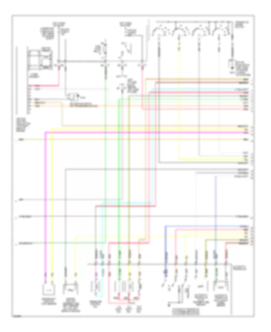
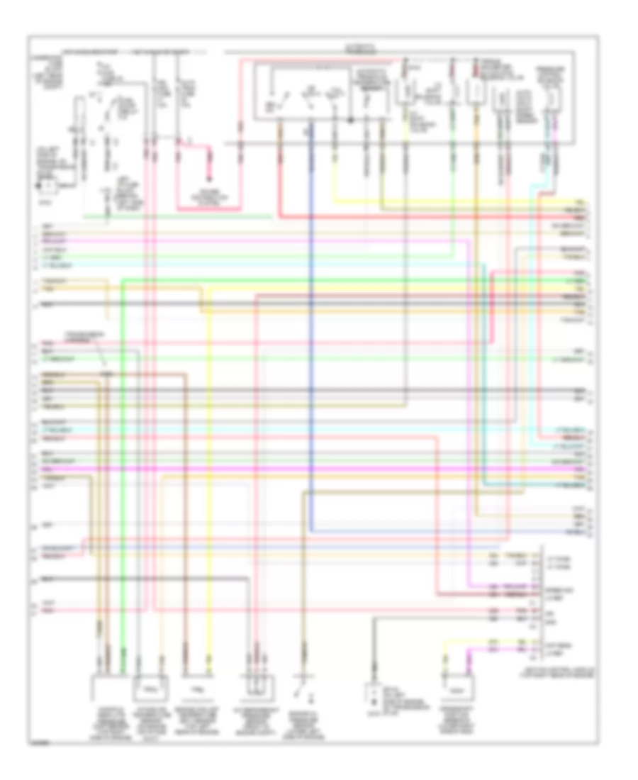
2.2L VIN F, Engine Performance Wiring Diagram (2 of 3) for Pontiac Grand Am SC/T 2005
List of elements for 2.2L VIN F, Engine Performance Wiring Diagram (2 of 3) for Pontiac Grand Am SC/T 2005:
- 1-2 shift sol
- 2-3 shift sol
- A7 pnk
- Automatic transaxle
- Automatic transaxle fluid pressure manual valve position switch
- Automatic transaxle fluid temperature sensor
- Automatic transaxle input shaft speed sensor
- B10
- Crankshaft position (ckp) sensor
- D5 pnk
- Engine coolant temperature (ect) sensor (on top left rear of engine)
- F/p-injr fuse 48 15a
- Fuel pump relay
- G102
- G103
- Gnd
- Hot in run or start
- Ign mod fuse 41 10a
- Ignition coils
- Ignition control module (icm) (top right rear of engine)
- Inter- connect
- Left i/p fuse block (behind left side of dash)
- Pnk
- Pressure control sol
- Red
- Release tcc
- Rev
- S103
- Splice pack sp102 (left side of engine, in front of starter)
- Splice pack sp103 (on transmission stud)
- Tan
- Tcc pwm sol
- Transaxle range switch
- Underhood fuse block (left rear of engine compt)
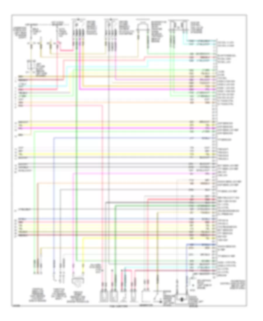
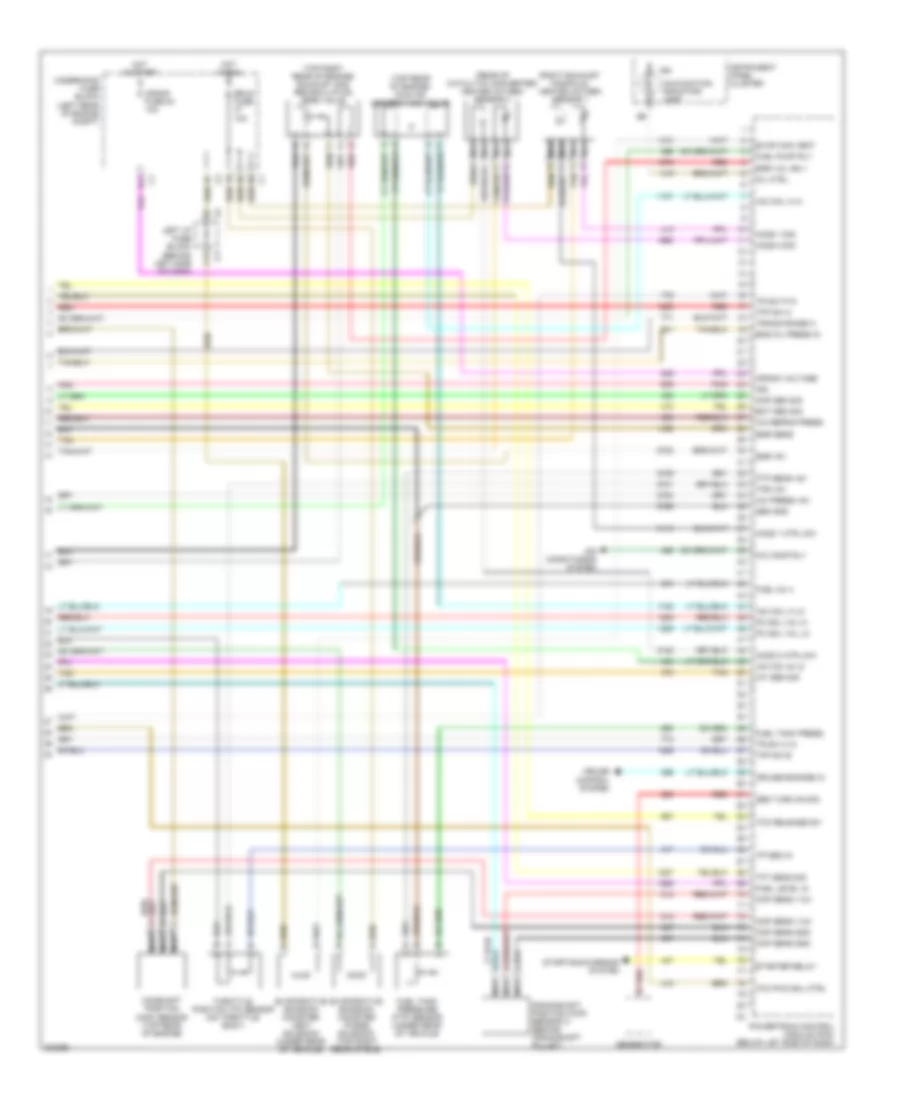
2.2L VIN F, Engine Performance Wiring Diagram (3 of 3) for Pontiac Grand Am SC/T 2005
List of elements for 2.2L VIN F, Engine Performance Wiring Diagram (3 of 3) for Pontiac Grand Am SC/T 2005:
- (inj harn, 16 cm from c130)
- 1-2 ss
- 2-3 ss
- 5v ref
- A4 pnk
- Auto trans fuse 38 10a
- C11
- Ckp sens low ref
- Ckp sens sig
- Cmp sens sig
- Cruise engage sig
- Ect sens low ref
- Ect sens sig
- Engine oil pressure sensor (lower left side of eng)
- Erls fuse 47 10a
- Evap purge sol
- Evaporative emission (evap) canister purge solenoid (top right rear of engine)
- Fuel injectors
- G102
- Gen field duty sig
- Gen turn on sig
- Generator
- Ground
- Heated oxygen sensor 1 (on right exhaust manifold)
- Heated oxygen sensor 2 (on rear of catalytic converter)
- Ho2s 1 high sig
- Ho2s 1 htr ctrl
- Ho2s 1 low sig
- Ho2s 2 high sig
- Ho2s 2 htr ctrl
- Ho2s 2 low sig
- Hot in run
- Hot in run or start
- Iac coil a high
- Iac coil a low
- Iac coil b high
- Iac coil b low
- Ic timing ctrl
- Idle air control (iac) valve (top rear of engine)
- Inj 1 ctrl
- Inj 2 ctrl
- Inj 3 ctrl
- Inj 4 ctrl
- Iss high
- Iss low
- Knock sens low ref
- Knock sens sig
- Knock sensor (lower left side of engine)
- Left i/p fuse block (behind left side of dash)
- Manifold absolute pressure (map) sensor (top right side of engine)
- Map sens low ref
- Map sens sig
- Nca
- Oil press sig
- Pc sol high
- Pc sol low
- Pnk
- Powertrain control module (pcm) (below left side of dash)
- Red
- S101
- Splice pack sp102 (left side of engine)
- Tan
- Tcc release sig
- Tcc sol
- Tfp sw b
- Tfp sw c
- Tft sens sig
- Tft sesn low ref
- Throttle position (tp) sensor (on throttle body)
- Tp sens 5v ref
- Tp sens low ref
- Tp sens sig
- Trs sig a
- Trs sig b
- Trs sig c
- Trs sig p
- Underhood fuse block (left rear of engine compt)
- Vehicle speed sensor (vss) (at rear of engine/transaxle)
- Vss high
- Vss low
3.4L VIN E
3.4L VIN E, Engine Performance Wiring Diagram (1 of 3) for Pontiac Grand Am SC/T 2005
List of elements for 3.4L VIN E, Engine Performance Wiring Diagram (1 of 3) for Pontiac Grand Am SC/T 2005:
- (below dash, left of steering column)
- (injector harness, 16 cm from c130)
- (under right side of dash) sp302
- 1-2 ss ctrl
- 2-3 ss ctrl
- 5 volt ref a
- A/c press gnd
- A/t iss hi
- A/t iss lo
- B12
- Battery
- Body control module (below right side of dash)
- Cmp sens
- Cooling fans system
- Cruise control system
- Cruise disable
- Cruise fuse e 10a
- Data link connector
- Egr sen gnd
- Egr val ctrl
- Engine spd sig
- Evap purge
- Fuel inj 1
- Fuel inj 2
- Fuel inj 3
- Fuel inj 5
- Fuel inj 6
- Fuel injectors
- Fuel pump and sender assembly (under rear of vehicle)
- Fuel pump motor
- G102
- G302
- Hi spd sig
- Ho2s 1 lo
- Ho2s 2 lo
- Ho2s low sig
- Hot at all times
- Hot in acc, run or start
- Hot in run
- Hot in run or start
- Iac coil b hi
- Ic ref lo
- Ic timing
- Ign
- Instrument cluster system
- Knock sensor (lower left side of eng)
- Ks signal
- Left i/p fuse block (behind left side of dash)
- Lo spd sig
- Maf sen sig
- Mass airflow sensor (top rear of engine)
- Medium spd sig
- Park/neutral position switch (on left front top of transaxle)
- Pcm acc fuse g 10a
- Pcm batt fuse 44 10a
- Pcm gnd
- Pcm ground
- Pcm/ign fuse 39 10a
- Pnk
- Pnk c
- Power distri- bution system
- Powertrain control module (pcm) (below left side of dash)
- Right i/p fuse block (behind right side of dash)
- S101
- Sen gnd
- Serial data
- Sp102 (left side of engine, in front of starter)
- Tan
- Tcc bk sw
- Tcc/ brake switch (below left side of dash)
- Tft sen lo
- Tr sw input b
- Under- hood fuse block (left rear of engine compt)
- Vehicle speed sensor (at rear of engine/transaxle)
- Vss hi
- Vss lo
- Vss out
3.4L VIN E, Engine Performance Wiring Diagram (2 of 3) for Pontiac Grand Am SC/T 2005
List of elements for 3.4L VIN E, Engine Performance Wiring Diagram (2 of 3) for Pontiac Grand Am SC/T 2005:
- (on left side of engine, on transmission stud) sp103
- (transmission harness)
- 1-2 shift solenoid valve
- 2-3 shift solenoid valve
- A/c refrigerant pressure sensor (front of engine compt)
- Auto tran fuse 10a
- Auto- matic input shaft speed sensor
- Automatic transaxle
- Automatic transaxle temperature sensor
- B10
- Ckp sens
- Crankshaft position sensor b (lower right side of eng)
- Dr sw
- Engine coolant temperature (ect) sensor (top left rear of engine)
- Engine oil pressure sensor (lower left side of engine)
- F/p injr fuse 48 15a
- Fuel pump relay
- G103
- Gnd
- Hot in run or start
- Ic timing
- Ign
- Ign mod fuse 10a
- Ignition control module (top right rear of engine)
- Intake air temperature sensor (on engine air intake duct)
- Left i/p fuse block (behind c3 left side of dash)
- Lo ref
- Manifold absolute pressure (map) sensor (top right side of engine)
- Pnk
- Power distribution system
- Pressure control solenoid valve
- Red
- Rev sw
- S102
- S103
- Sp103 (on left side of engine, on transmission stud)
- Speed sig
- Tan
- Tan b
- Tcc sw
- Torque converter clutch pwm solenoid valve
- Underhood fuse block (left rear of engine compt)
3.4L VIN E, Engine Performance Wiring Diagram (3 of 3) for Pontiac Grand Am SC/T 2005
List of elements for 3.4L VIN E, Engine Performance Wiring Diagram (3 of 3) for Pontiac Grand Am SC/T 2005:
- (rear of catalytic converter) heated oxygen sensor 2
- (right exhaust manifold) heated oxygen sensor 1
- (top rear of engine) idle air control (iac) valve
- (top right rear of engine) exhaust gas recirculation (egr) valve
- A/c comp rly
- A/c press +5v
- A/c refrig press
- Air conditioning system
- B11
- C11
- Camshaft position (cmp) sensor (top rear of engine)
- Ckp sens +12v
- Ckp sens gnd
- Cmp sens +12v
- Cmp sens gnd
- Crank fuse 54 10a
- Crank voltage
- Crankshaft position (ckp) sensor a (behind crankshaft pulley)
- Cruise control system
- Cruise engage in
- Ect sen sig
- Egr +5v
- Egr sens
- Egr val ign +
- Eng oil press in
- Erls fuse 10a
- Evap can vent
- Evaporative emission canister purge solenoid (top right rear of eng)
- Evaporative emission canister vent solenoid (under rear of vehicle)
- Ftp sens +5v
- Fuel inj 4
- Fuel level in
- Fuel pump rly
- Fuel tank press
- Fuel tank pressure (ftp) sensor (under rear of vehicle)
- Gen turn on sig
- Generator
- Ho2s 1 htr low
- Ho2s 1 sig
- Ho2s 2 htr low
- Ho2s 2 sig
- Hot in run
- Hot in start
- Iac coil a hi
- Iac coil a lo
- Iac coil b lo
- Iat sen sig
- Ign
- Instrument panel cluster
- Left i/p fuse block (behind left side of dash)
- Malfunction indicator lamp
- Map sen sig
- Mil ctrl
- Nca
- Pc sol val hi
- Pc sol val lo
- Pnk
- Powertrain control module (pcm) (below let side of dash)
- Red
- Red b
- Sen gnd
- Starter relay
- Starting/charging system
- Tan
- Tcc pwm sol ctrl
- Tcc release sw
- Tfp sw b
- Tfp sw c
- Tft sens sig
- Throttle position (tp) sensor (on throttle body)
- Tp sen in
- Tps +5v
- Tr sw c in
- Tr sw p in
- Trans range a
- Underhood fuse block (left rear of engine compt)
EXTERIOR LIGHTS
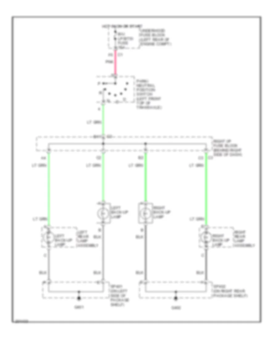
Back-up Lamps Wiring Diagram for Pontiac Grand Am SC/T 2005
List of elements for Back-up Lamps Wiring Diagram for Pontiac Grand Am SC/T 2005:
- B/u lp/btsi fuse 15a
- B11
- C3 c3
- G401
- G402
- Hot in on or start
- Left back-up lamp
- Left rear lamp assembly
- Park/ neutral position switch (left front top of transaxle)
- Pnk
- Right back-up lamp
- Right i/p fuse block (behind right side of dash)
- Right rear lamp assembly
- Sp401 (on left side of package shelf)
- Sp402 (on right rear package shelf)
- Underhood fuse block (left rear of engine compt)
Exterior Lamps Wiring Diagram for Pontiac Grand Am SC/T 2005
List of elements for Exterior Lamps Wiring Diagram for Pontiac Grand Am SC/T 2005:
- (below right side of dash) body control module (bcm)
- A10
- A12
- Air conditioning system
- Auto park lamp cntrl relay 19
- B10
- B11
- B12
- B12 c2
- Battery voltage
- C10
- C12
- C2 b
- Center high mounted stop lamp (chmsl)
- F12
- G101
- G201
- G202
- G401
- G402
- Ground
- Ground distribution system
- Hazard lps fuse 15a
- Hazard switch
- Head
- Hot at all times
- Hot in on or start
- Ign 1 voltage
- Instrument panel cluster (ipc)
- Interior lights system
- Left
- Left front auxiliary park lamp
- Left front marker lamp
- Left front park/turn signal lamp
- Left i/p fuse block (behind left side of dash)
- Left rear lamp assembly
- Left turn indicator
- Left turn signal lamp
- License lamp
- Off
- On sig
- Park
- Park lps fuse 15a
- Pnk
- Power
- Right
- Right front auxiliary park lamp
- Right front marker lamp
- Right front park/ turn signal lamp
- Right i/p fuse block (behind right side of dash)
- Right rear lamp assembly
- Right turn indicator
- Right turn signal lamp
- Rly ctrl
- Sounds system
- Sp101 (on left side of engine compt, near strut
- Sp101 (on left side of engine compt, near strut)
- Sp201 (on left front of dash, near fuse block
- Sp202 (on left front side of dash, near fuse block)
- Sp401 (on left side of package shelf)
- Sp402 (on right rear package shelf)
- Stop
- Stop lamp switch (below left side of dash)
- Stop lps fuse 20a
- Turn
- Turn lps fuse 10a
- Turn signal flasher
- Turn signal/ multi- function switch
- Underhood fuse block (left rear of engine compartment)
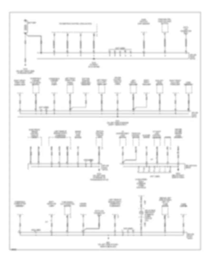
GROUND DISTRIBUTION
Ground Distribution Wiring Diagram (1 of 3) for Pontiac Grand Am SC/T 2005
List of elements for Ground Distribution Wiring Diagram (1 of 3) for Pontiac Grand Am SC/T 2005:
- (behind left side of dash) left i/p fuse block
- (if equipped) right steering wheel controls
- (left rear of engine compt) underhood fuse block
- (not used)
- (not used) b
- A/t
- A/t shift lock control solenoid
- A10
- Battery
- Blower motor
- Brake fluid level switch
- C12
- C206
- C207
- Cigar lighter
- Coolant level switch
- Cruise control module (ccm)
- D10
- Data link connector (dlc)
- Daytime running lamps (drl) resistor
- E10
- Electronic brake control module (ebcm)
- G101 (on left side of engine compt, near strut)
- G102 (in front of starter)
- G103 (on left side of engine, on transmission stud)
- G104 (on left front side of engine compt)
- G201 (on left side of dash, near fuse block)
- G203 (below right side of dash)
- Hazard switch
- Heated oxygen sensor (ho2s) sensor 2
- Horn assembly
- I/p compartment lamp/ switch
- Ignition control module (icm)
- Inflatable restraint steering wheel module coil
- Left front auxiliary park lamp
- Left front fog lamp
- Left front park/turn signal lamp
- Mass air flow (maf) sensor
- Nca c
- Park/neutral position (pnp) switch
- Powertrain control module (pcm)
- Radio
- Right front auxiliary park lamp
- Right front fog lamp
- Right front park/turn signal lamp
- Shift indicator lamp
- Splice pack sp101
- Splice pack sp102
- Splice pack sp103
- Splice pack sp201
- Splice pack sp203
- Traction control switch
- Turn signal/ multi-function switch
- Windshield washer fluid level switch
- Windshield washer fluid pump
- Windshield wiper motor assembly
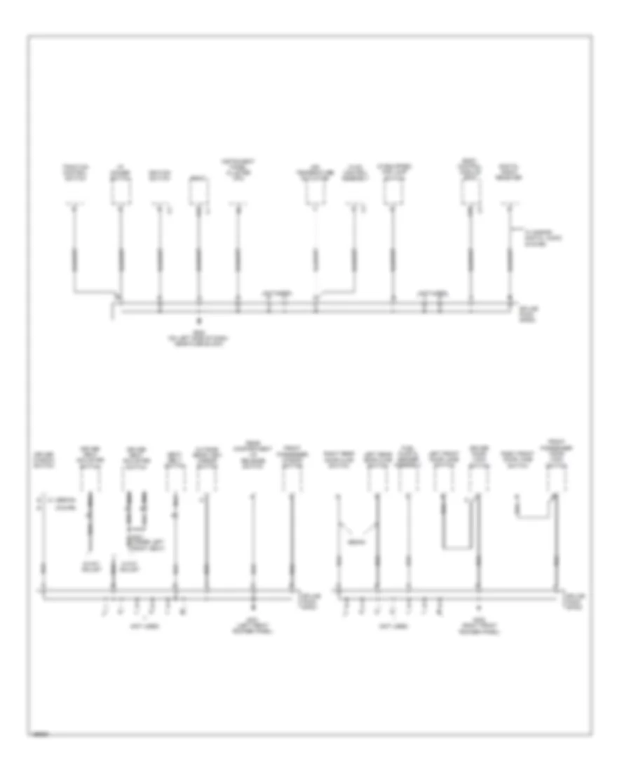
Ground Distribution Wiring Diagram (2 of 3) for Pontiac Grand Am SC/T 2005
List of elements for Ground Distribution Wiring Diagram (2 of 3) for Pontiac Grand Am SC/T 2005:
- (coupe)
- (if equipped) fog lamp switch
- (not used)
- (sedan)
- 4-way adjust
- 6-way adjust
- A10
- A12
- Air temperature actuator
- Body control module (bcm)
- Digital radio receiver
- Driver door lock switch
- Driver seat adjuster switch
- Driver window switch
- Front passenger door lock switch
- Front passenger window switch
- Fuel pump & sender assembly
- G202 (on left side of dash, near fuse block)
- G301 (left front rocker panel)
- G302 (right front rocker panel)
- Hvac control assembly
- I/p dimmer switch
- Ignition switch
- Instrument panel cluster (ipc)
- Left front door jamb switch
- Left rear door ajar switch
- Nca
- Outside rear view mirror switch
- Radio
- Rear compartment lid release switch
- Right front door jamb switch
- Right rear door ajar switch
- Seat belt switch
- Sedan
- Splice pack sp202
- Splice pack sp301
- Splice pack sp302
- Traction control switch
- W/ s-band digital audio system
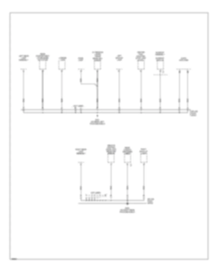
Ground Distribution Wiring Diagram (3 of 3) for Pontiac Grand Am SC/T 2005
List of elements for Ground Distribution Wiring Diagram (3 of 3) for Pontiac Grand Am SC/T 2005:
- (not used)
- (w/ reading lamps) inside rearview mirror
- Audio amplifier
- Center high mounted stop lamp (chmsl)
- Dome lamp
- G401 (on rear left package shelf)
- G402 (on right rear package shelf)
- Left backup lamp
- Left rear lamp assembly
- License lamp
- Rear compartment lid release actuator
- Rear window defogger grid
- Remote control door lock receiver (rcdlr)
- Right back-up lamp
- Right rear lamp assembly
- Splice pack sp401
- Splice pack sp402
- Sunroof assembly
- Sunroof module
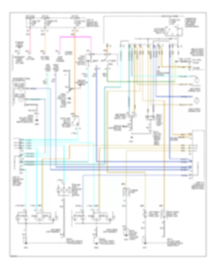
HEADLIGHTS
Headlights Wiring Diagram for Pontiac Grand Am SC/T 2005
List of elements for Headlights Wiring Diagram for Pontiac Grand Am SC/T 2005:
- A10 c3
- A12
- Al sens ref
- Al sens sig
- Ambient light sensor (on top of dash trim pad)
- Auto hdlp ctrl relay
- B12 c3
- B3 c3
- Batt
- Body control module (bcm) (below right side of dash)
- C pnk
- C4 c3
- C9 c2
- Computer data lines system
- D10 c2
- D11 c2
- Daytime running lamps (drl) resistor (on center rear of impact bar)
- Drl relay
- F12
- Flash-to -pass
- Flash-to -pass high
- Fog lamp switch
- Fog lp relay
- Fog lp sw
- Fog lps fuse f 10a
- Fog lps relay
- G101
- G201
- G202
- Head
- High beam
- High beam in
- High beam ind
- Hot at all times
- Hot in run
- Htr a/c fuse 46 10a
- Instrument panel cluster (ipc)
- Left front fog lamp
- Left headlamp
- Lh hdlp fuse 51 15a
- Lo beam rly
- Logic
- Low
- Low beam
- Low beam in
- Off
- On indicator
- Park
- Park brake switch (part of park brake assembly)
- Pk brake sw
- Pnk
- Q10
- Q11
- Q12
- Rh hdlp fuse 50 15a
- Right front fog lamp
- Right headlamp
- Right i/p fuse block (behind right side of dash)
- S10
- S11
- S12
- Serial data
- Sp101 (on left side of engine compartment, near strut)
- Sp101 (on left side of engine compt, near strut)
- Sp201 (on left front side of dash, near fuse block)
- Sp202 (on left front side of dash, near fuse block)
- Turn signal/ multi-function switch
- Underhood fuse block (left rear of engine compartment)
- Underhood fuse block (left rear of engine compt)
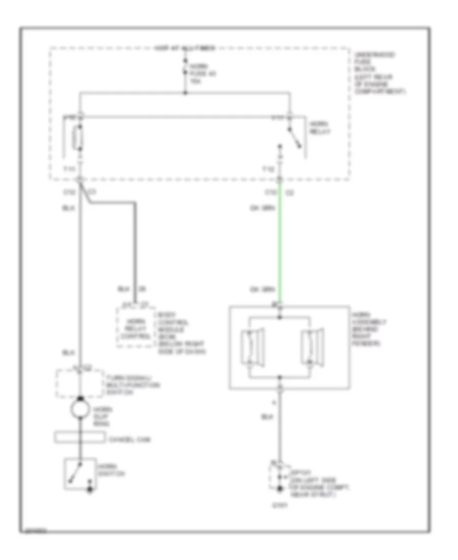
HORN
Horn Wiring Diagram for Pontiac Grand Am SC/T 2005
List of elements for Horn Wiring Diagram for Pontiac Grand Am SC/T 2005:
- Body control module (bcm) (below right side of dash)
- C12
- C2 a
- Cancel cam
- G101
- Horn assembly (behind right fender)
- Horn fuse 43 15a
- Horn relay
- Horn relay control
- Horn slip ring
- Horn switch
- Hot at all times
- Sp101 (on left side of engine compt, near strut)
- T11
- T12
- Turn signal/ multi-function switch
- Underhood fuse block (left rear of engine compartment)
- V11
- V12
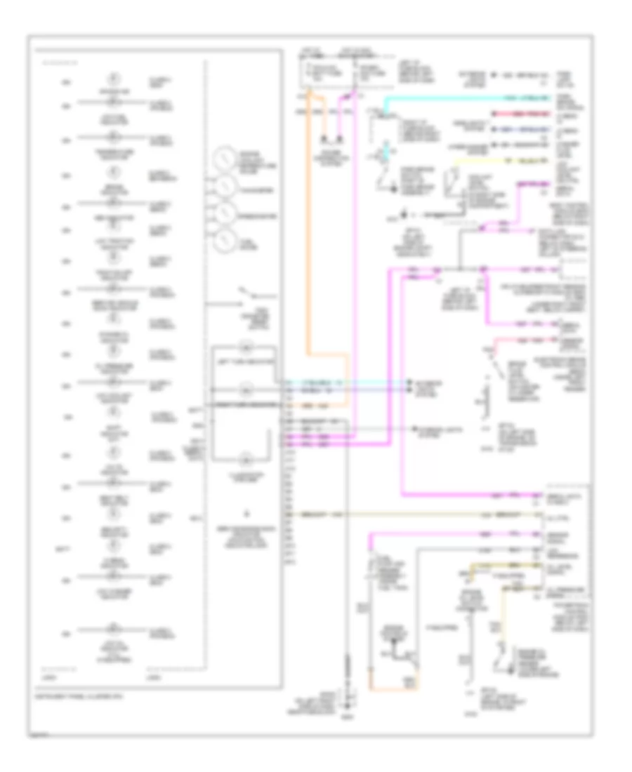
INSTRUMENT CLUSTER
Instrument Cluster Wiring Diagram for Pontiac Grand Am SC/T 2005
List of elements for Instrument Cluster Wiring Diagram for Pontiac Grand Am SC/T 2005:
- A10
- A11
- A12
- Abs indicator
- Air bag ind
- B10
- B11
- B12
- Batt
- Body control module (bcm) (below right side of dash)
- Brake fluid level switch (on master cylinder reservoir)
- Brake indicator
- C6 sensor signal
- C8 serial data
- Change oil indicator
- Class 2 (bcm)
- Class 2 (bcm/ebcm)
- Class 2 (ebcm)
- Class 2 (ipc/bcm)
- Class 2 (pcm/bcm)
- Class 2 (sdm)
- Class 2 serial data
- Coolant
- Coolant level switch (in right side of engine compartment)
- Data link connector (dlc) (below dash, left of steering column)
- Electronic brake control module (ebcm) (inside left front fender)
- Engine
- Engine controls system
- Engine oil level switch connector
- Engine oil pressure sensor (lower left side of engine)
- Exterior lights system
- Fuel
- Fuel pump and sender assembly (inside fuel tank)
- G101
- G102
- G103
- G202
- Gauge
- Gnd
- Headlights system
- Hi beam in
- Hi beam indicator
- Hot at all times
- Hot in acc run or start
- If equipped
- Ign
- Ign 0
- Illumination (5 bulbs)
- Inflatable restraint sensing & diagnostic module (sdm) (w/ abs) (under right front seat, below carpet)
- Instrument panel cluster (ipc)
- Interior lights system
- Ipc/bfc acc fuse 10a
- Ipc/hvac batt fuse 10a
- Left i/p fuse block (behind left side of dash)
- Left turn indicator
- Lo beam in
- Logic
- Low coolant indicator
- Low coolant level ind ctrl
- Low fuel indicator
- Low oil indicator (3.4l) (if equipped)
- Low reference
- Low traction indicator
- Low washer indicator
- Mil ctrl
- Oil level signal
- Oil pressure indicator
- Oil pressure signal
- Park brake sw signal
- Park brake switch (part of park brake assembly)
- Park lamp sw on
- Pnk
- Power distribution system
- Powertrain control module (pcm) (below left side of dash)
- Right i/p fuse block (behind right side of dash)
- Right turn indicator
- Seat belt indicator
- Security indicator
- Sensor signal
- Serial data
- Serial data class 2
- Service engine soon indicator (malfunction indicator lamp)
- Service vehicle soon indicator
- Shift indicator (m/t)
- Sp101 (on left side of engine compt, near strut)
- Sp102 (left side of engine, in front of starter)
- Sp103 (on left side of engine, on transmission stud)
- Sp202 (on left front side of dash, near fuse block)
- Speedometer
- Tachometer
- Temperature
- Temperature indicator
- Traction off indicator
- Trip/ odometer reset switch
- Volts indicator
- Washer fluid level
- Wiper/washer system
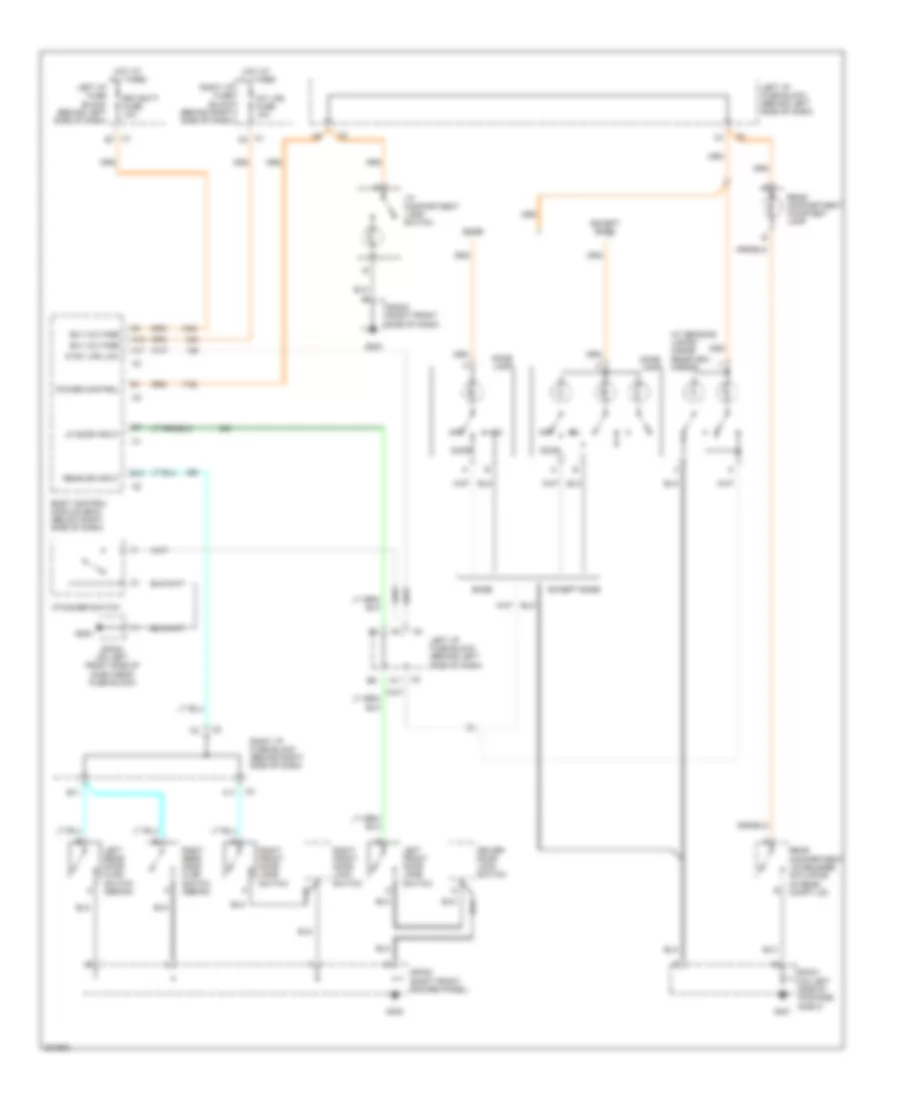
INTERIOR LIGHTS
Courtesy Lamps Wiring Diagram for Pontiac Grand Am SC/T 2005
List of elements for Courtesy Lamps Wiring Diagram for Pontiac Grand Am SC/T 2005:
- (in rear compt lid)
- (w/ reading lamps) inside rearview mirror
- A11
- A12
- B(+) voltage
- B10
- B11
- Base
- Bfc batt fuse 10a
- Body control module (bcm) (below right side of dash)
- C11
- Ctsy lps low
- Dome lamp
- Door
- Driver door lock switch
- Except base
- G202
- G203
- G302
- G401
- Hot at all times
- I/p compartment lamp/ switch
- I/p dimmer switch
- Int lps fuse 10a
- Left front door jamb switch
- Left i/p fuse block (behind left side of dash)
- Left rear door ajar switch (sedan)
- Lf door input
- Off
- Power control
- Rear compartment courtesy lamp
- Rear compartment lid release actuator
- Rear dr input
- Right front door jamb switch
- Right front door lock switch
- Right i/p fuse block (behind right side of dash)
- Right rear door ajar switch (sedan)
- Sp202 (on left front side of dash near fuse block)
- Sp203 (right front side of dash)
- Sp302 (right front rocker panel)
- Sp401 (on left side of package shelf)
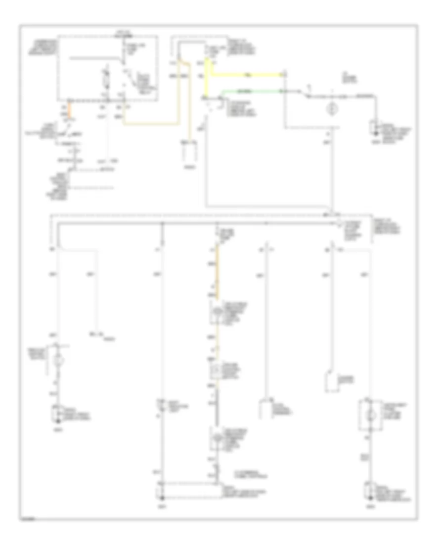
Instrument Illumination Wiring Diagram (1 of 2) for Pontiac Grand Am SC/T 2005
List of elements for Instrument Illumination Wiring Diagram (1 of 2) for Pontiac Grand Am SC/T 2005:
- Auto park lamp control relay
- B12
- Body control module (bcm) (behind right side of dash)
- C1 b1
- C1 b4
- C2 j
- C3 b5
- Cruise control on/off switch
- Cruise sw lps fuse 2a
- E12
- F12
- G201
- G202
- G203
- Hazard switch
- Head
- Hot at all times
- Hvac control assembly
- I/p dimmer switch
- I/p dimming module (behind left side of dash)
- Inflatable restraint steering wheel module coil
- Inst lps fuse 10a
- Instrument panel cluster (5 bulbs)
- Off
- Park
- Park lps fuse 15a
- Radio
- Right i/p fuse block (behind right side of dash)
- Shift indicator light
- Sp201 (on left side of dash, near fuse block)
- Sp202 (on left front side of dash, near fuse block)
- Sp203 (right front side of dash)
- To right i/p fuse block (diagram 2 of 2)
- Traction control switch
- Turn/ signal multi-function switch
- Underhood fuse block (left rear of engine compt)
- W/ steering wheel controls
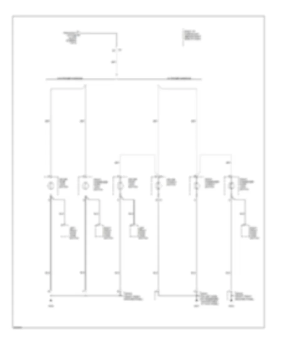
Instrument Illumination Wiring Diagram (2 of 2) for Pontiac Grand Am SC/T 2005
List of elements for Instrument Illumination Wiring Diagram (2 of 2) for Pontiac Grand Am SC/T 2005:
- B c1
- Driver door lock switch
- Driver window switch
- From right a i/p fuse block (diagram 1 of 2)
- Front passenger door lock switch
- Front passenger window switch
- G301
- G302
- Left front door jamb switch
- Right front door jamb switch
- Right i/p fuse block (behind right side of dash)
- Sp301 (on left side of passenger compartment, at kick panel)
- Sp302 (right front rocker panel)
- W/ power windows
- W/o power windows
POWER DISTRIBUTION
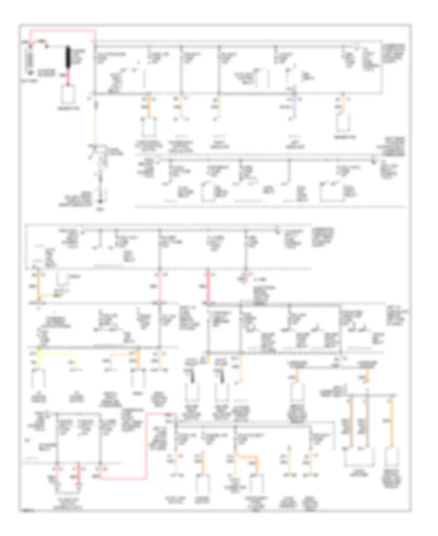
Power Distribution Wiring Diagram (1 of 2) for Pontiac Grand Am SC/T 2005
List of elements for Power Distribution Wiring Diagram (1 of 2) for Pontiac Grand Am SC/T 2005:
- (left rear of engine compartment) underhood fuse block
- 4 speaker system
- 4-way adjust
- 6-way adjust
- 8 speaker system
- A nca
- A10
- A12
- Abs fuse 50a
- Audio amplifier
- Auto hdlp control relay
- Auto prk lmp ctrl relay
- Aux pwr/cigar fuse 20a
- B10
- B11
- B12
- Battery
- Bfc batt fuse 10a
- Body control module (bcm)
- C12
- Cigar lighter
- Cool fan 1 fuse 30a
- Cool fan 1 relay
- Cool fan 2 fuse 15a
- Cool fan 2 relay
- Cool fan mode relay
- D10 d10
- Data link connector (dlc)
- Digital radio receiver (if equipped)
- Dr lock fuse 15a
- Driver door lock relay
- Driver door unlock relay
- Driver door unlock relay (w/ rke)
- Driver seat adjuster switch
- Drl relay
- E11
- E12
- Electronic brake control module (ebcm)
- F nca
- F12
- Fog lps fuse 10a
- Fog lps relay
- From a gen bat fuse (diagram 1 of 2)
- From c abs fuse (diagram 1 of 2)
- From cool b fan 2 relay (diagram 1 of 2)
- Fusible link (10 ga- rust)
- G201
- Gen batt fuse 10a
- Generator
- Hazard lps fuse 15a
- Hazard switch
- Hi blo mot fuse 30a
- Horn fuse 15a
- Horn relay
- Hvac blower relay
- Hvac control assembly
- I/p dimmer switch
- I/p dimming module
- Ign sw batt 1 fuse 40a
- Ign sw- batt 2 fuse 30a
- Inst lps fuse 10a
- Instrument panel cluster (ipc)
- Int lps fuse 10a
- Interior & exterior lights systems
- Ipc/hvac batt fuse 10a
- K10
- L/h bec batt 1 fuse 40a
- L/h bec batt 2 fuse 30a
- Left headlamp
- Left i/p fuse block (behind left side of dash)
- Lh hdlp fuse 15a
- Outside rearview mirror switch
- Park lps fuse 15a
- Pcm batt fuse 10a
- Powertrain control module (pcm)
- Pwr mirror fuse 10a
- Pwr seat circuit breaker 25a
- Q12
- R/h bec batt fuse 30a
- R11
- Radio
- Radio batt fuse 15a
- Red
- Red a
- Remote control door lock receiver (rcdlr)
- Rh hdlp fuse 15a
- Right headlamp
- Right i/p fuse block (behind right side of dash)
- Rr defog fuse 30a
- Rr defog relay
- S10
- Sp201 (on left front side of dash, near fuse block)
- Sp311 (under right front seat)
- Starter relay
- Starter solenoid
- Stop lamp switch
- Stop lps fuse 20a
- To cool fan relay 1 (diagram 1 of 2)
- To hi blo mot fuse (diagram 1 of 2)
- To ign-sw batt 2 fuse (diagram 1 of 2)
- To ignition switch (diagram 2 of 2)
- Trunk rel relay
- Trunk rel/ radio amp fuse 20a
- Turn signal/ multifunction switch
- Underhood fuse block (left rear of engine compt)
- V11
- V12
- W/ abs
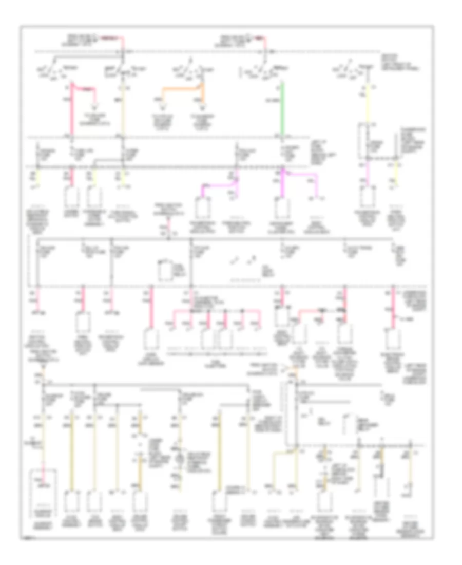
Power Distribution Wiring Diagram (2 of 2) for Pontiac Grand Am SC/T 2005
List of elements for Power Distribution Wiring Diagram (2 of 2) for Pontiac Grand Am SC/T 2005:
- (diagram 1 of 2)
- (in injector harness, 16 cm from c130) s101
- (left rear of engine compt) underhood fuse block
- 1-2 shift solenoid (1-2 ss) valve
- 2-3 shift solenoid (2-3 ss) valve
- A/c bfc fuse 10a
- A/c comp relay
- A11
- A12
- A7 c3
- Abs/ evo/ ign fuse 15a
- Acc
- Air bag fuse 10a
- Air temperature actuator
- Auto trans fuse 10a
- B/u lp/ btsi fuse 15a
- B11
- Body control module (bcm)
- C2 b
- C2 c
- C2 c2
- C3 a8
- C3 c11
- Crank fuse 10a
- Cruise control module (ccm)
- Cruise control on/off switch
- Cruise fuse 10a
- Cruise sw fuse 2a
- Driver window switch
- Drl relay
- Electronic brake control module (ebcm)
- Erls fuse 10a
- Evaporative emission (evap) canister purge solenoid
- Evaporative emission (evap) canister vent solenoid
- F/p injr fuse 15a
- F11
- From ign sw batt 2 fuse d
- From ign sw e batt 1 fuse (diagram 1 of 2)
- From ignition switch (diagram 2 of 2)
- Front passenger window switch (coupe)
- Fuel injectors
- Fuel pump relay
- G (coupe)
- G (sedan)
- Hazard switch
- Heated oxygen sensor (ho2s) sensor 1
- Heated oxygen sensor (ho2s) sensor 2
- Htr a/c fuse 10a
- Hvac blower fuse 20a
- Hvac control assembly
- Ign mod fuse 10a
- Ignition control module (icm)
- Ignition switch (left front of instrument panel)
- Inflatable restraint sensing & diagnostic module (sdm)
- Inflatable restraint steering wheel module coil
- Instrument panel cluster (ipc)
- Ipc/bfc acc fuse 10a
- Left i/p fuse block (behind left side of dash)
- Left i/p fuse block (behind right side of dash)
- Lock
- Mass airflow (maf) sensor
- Nca
- Off
- Park/ neutral position switch (a/t)
- Park/neutral position switch
- Pcm acc fuse 10a
- Pcm ign fuse 10a
- Pnk
- Powertrain control module (pcm)
- Pwr wndw circuit breaker 25a
- Q11
- Rear defogger relay
- Red
- Right i/p fuse block (behind right side of dash)
- S103
- Start
- Sunroof assembly
- Sunroof fuse 20a
- Sunroof module
- Tcc/ brake switch
- To htr a/c ign fuse (diagram 2 of 2)
- To ign mod fuse (diagram 2 of 2)
- To sunroof fuse (diagram 2 of 2)
- Torque converter clutch pulse width modulation (tcc pwm) solenoid valve
- Turn lps fuse 10a
- Turn signal/ multifunction switch
- Under- hood fuse block (left rear of engine compt)
- Underhood fuse block (left rear of engine compt)
- W/ sunroof
- W/ abs
- Windshield wiper motor assembly
- Wiper fuse 25a
POWER DOOR LOCKS
Power Door Locks Wiring Diagram for Pontiac Grand Am SC/T 2005
List of elements for Power Door Locks Wiring Diagram for Pontiac Grand Am SC/T 2005:
- A10
- Battery (b+)
- Body control module (bcm) (below right side of dash)
- C10
- Computer data lines system
- D10
- Door lk
- Door lk/unlk in
- Door lock fuse 15a
- Door lock relay
- Door unlk
- Door unlock relay
- Driver door lk
- Driver door lock actuator
- Driver door lock switch
- Driver door unlock relay (w/ rke)
- E10
- E11
- F10
- Front passenger door lock actuator
- Front passenger door lock switch
- G11
- G201
- G302
- G402
- Ground
- H10
- H11
- Hot at all times
- Interior lights system
- J10
- K11
- Left i/p fuse block (behind left side of dash)
- Left rear door lock actuator
- Lock
- Remote control door lock receiver (rcdlr) (on rear package shelf)
- Right i/p fuse block (behind right side of dash)
- Right rear door lock actuator
- Serial data
- Sp201 (on left front side of dash, near fuse block)
- Sp302 (right front rocker panel)
- Sp311 (under right front seat)
- Sp402 (on right rear package shelf)
- Tan
- Trunk rel/ radio amp fuse 20a
- Unlock
- W/ 8 speaker audio system
- W/ rke
- W/o 8 speaker audio system
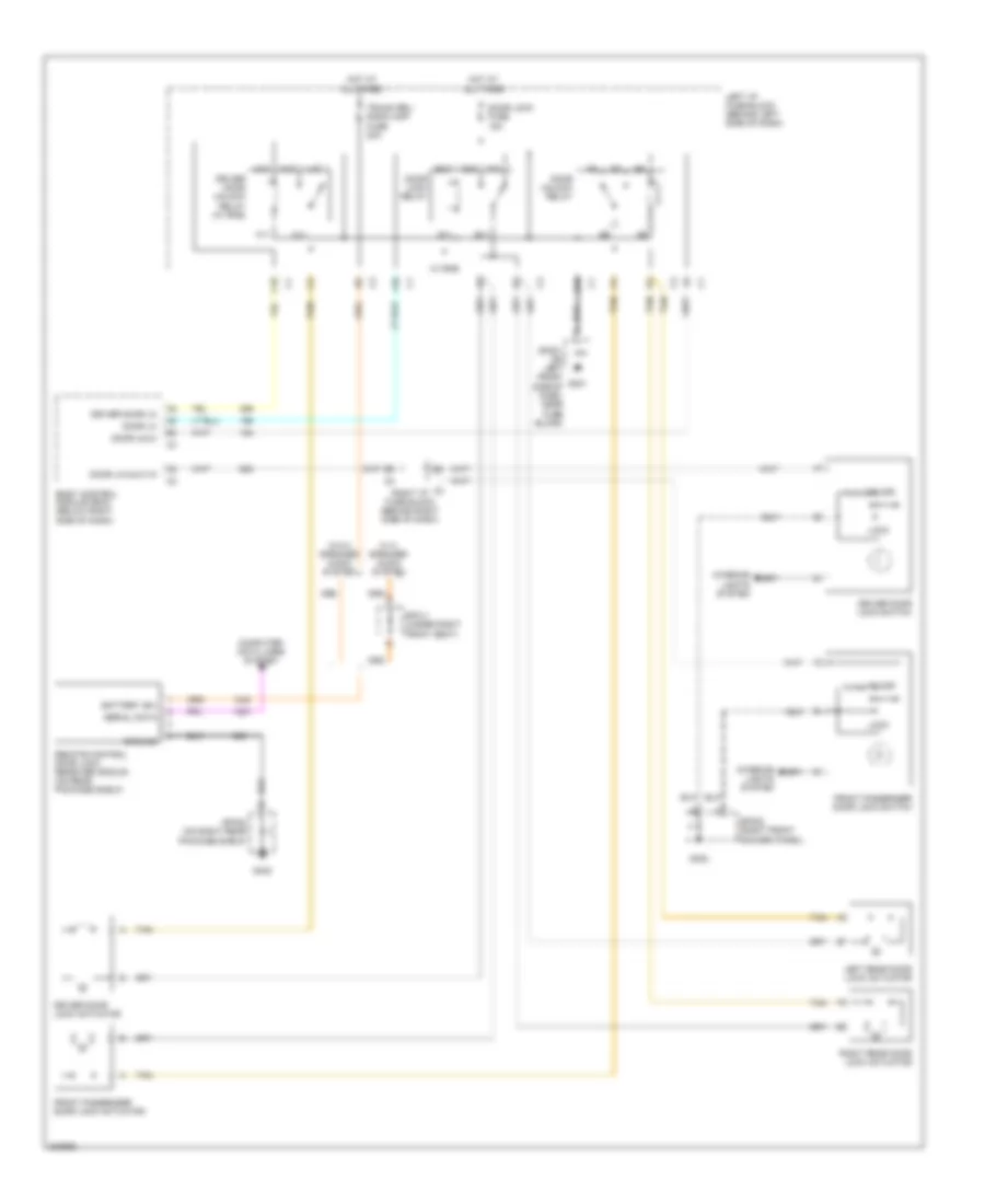
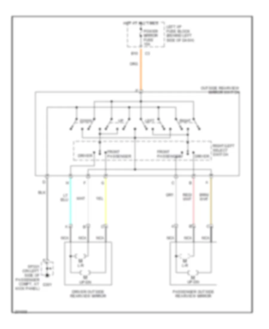
POWER MIRRORS
Power Mirrors Wiring Diagram for Pontiac Grand Am SC/T 2005
List of elements for Power Mirrors Wiring Diagram for Pontiac Grand Am SC/T 2005:
- B10
- Down
- Driver
- Driver outside rearview mirror
- Front passenger
- G301
- Hot at all times
- L-r
- Left
- Left i/p fuse block (behind left
- Nca
- Outside rearview mirror switch
- Passenger outside rearview mirror
- Power mirror fuse 10a
- Right
- Right/left select switch driver
- Side of dash)
- Sp301 (on left side of passenger compt, at kick panel)
- Up-dn
POWER SEATS
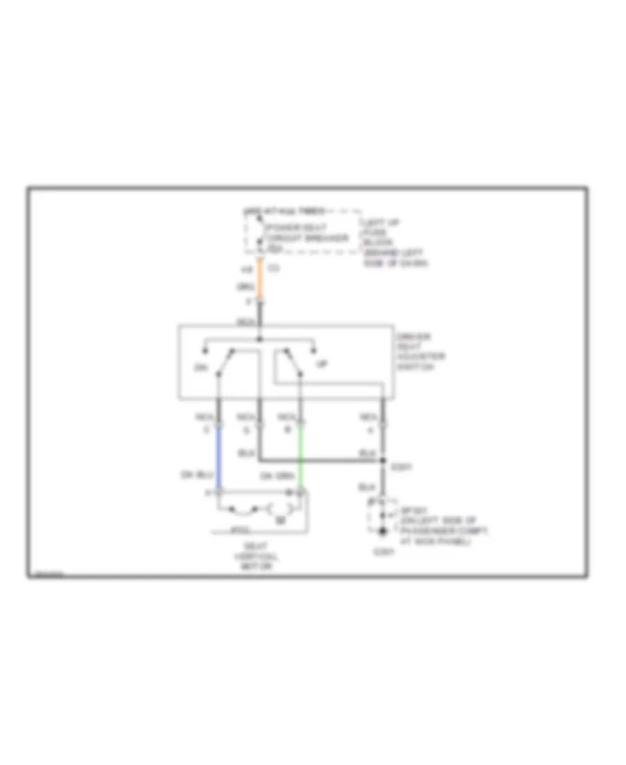
4-Way Adjustable Power Seat Wiring Diagram for Pontiac Grand Am SC/T 2005
List of elements for 4-Way Adjustable Power Seat Wiring Diagram for Pontiac Grand Am SC/T 2005:
- Driver seat adjuster switch
- G301
- Hot at all times
- Left i/p fuse block (behind left side of dash)
- Nca
- Power seat circuit breaker 25a
- Ptc
- S201
- Seat vertical motor
- Sp301 (on left side of passenger compt, at kick panel)
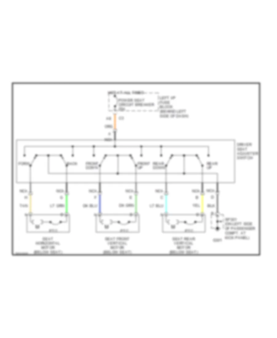
6-Way Power Seat Wiring Diagram for Pontiac Grand Am SC/T 2005
List of elements for 6-Way Power Seat Wiring Diagram for Pontiac Grand Am SC/T 2005:
- Back
- Driver seat adjuster switch
- Forw
- Front down
- Front up
- G301
- Hot at all times
- Left i/p fuse block (behind left side of dash)
- Nca
- Power seat circuit breaker 25a
- Ptc
- Rear down
- Rear up
- Seat front vertical motor (below seat)
- Seat horizontal motor (below seat)
- Seat rear vertical motor (below seat)
- Sp301 (on left side of passenger compt, at kick panel)
- Tan
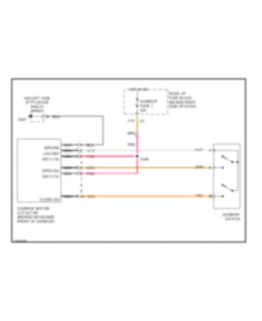
POWER TOP/SUNROOF
Power Top/Sunroof Wiring Diagram for Pontiac Grand Am SC/T 2005
List of elements for Power Top/Sunroof Wiring Diagram for Pontiac Grand Am SC/T 2005:
- (on left side of package shelf) sp401
- A12
- Close sig
- G401
- Ground
- Hot in on
- Ign 3 vol
- Low ref
- Nca
- Open sig
- Pnk
- Right i/p fuse block (behind right side of dash)
- S309
- Sunroof fuse 1 20a
- Sunroof motor/ actuator (behind headliner, front of sunroof)
- Sunroof switch
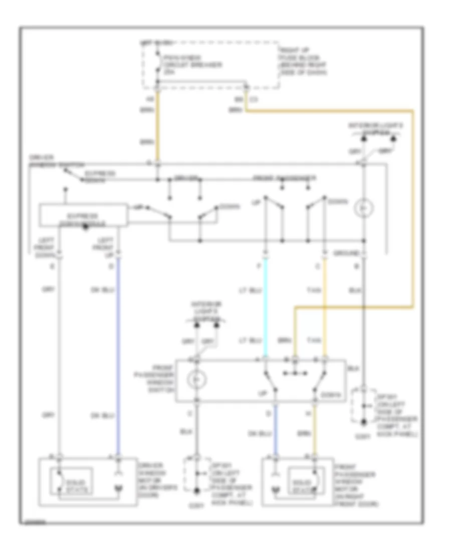
POWER WINDOWS
Power Windows Wiring Diagram, 2 Door for Pontiac Grand Am SC/T 2005
List of elements for Power Windows Wiring Diagram, 2 Door for Pontiac Grand Am SC/T 2005:
- C3 b8
- Down
- Driver
- Driver window motor (in driver's door)
- Driver window switch
- Express down
- Express down module
- Front passenger
- Front passenger window motor (in right front door)
- Front passenger window switch
- G301
- Ground
- Hot in on
- Interior lights system
- Left front down
- Left front up
- Pwn wndw circuit breaker 25a
- Right i/p fuse block (behind right side of dash)
- Solid state
- Sp301 (on left side of passenger compt, at kick panel)
- Tan
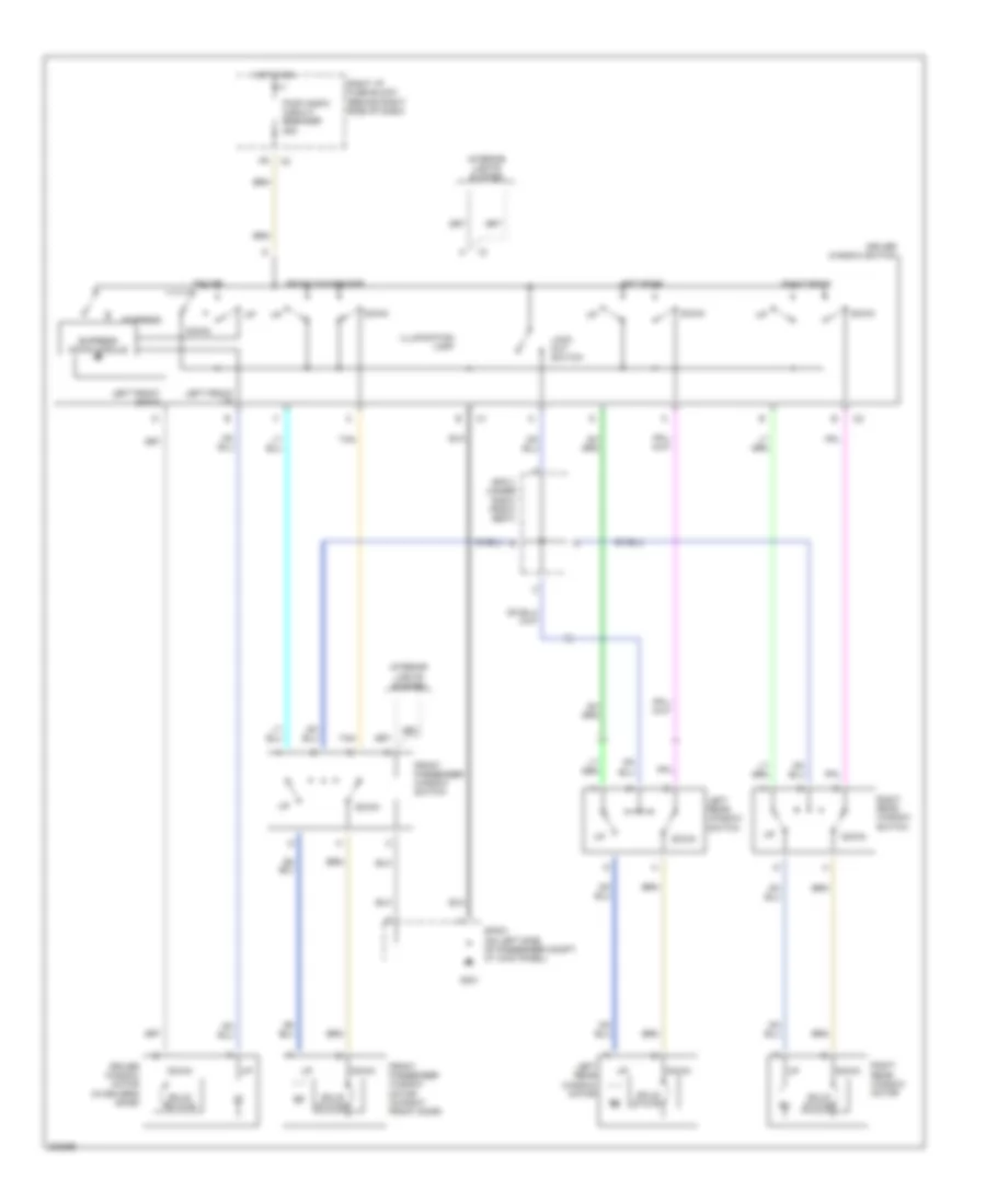
Power Windows Wiring Diagram, 4 Door for Pontiac Grand Am SC/T 2005
List of elements for Power Windows Wiring Diagram, 4 Door for Pontiac Grand Am SC/T 2005:
- Down
- Driver
- Driver window motor (in driver's door)
- Driver window switch
- Express
- Express down module
- Front passenger
- Front passenger window motor (in right front door)
- Front passenger window switch
- G301
- Hot in on
- Illumination lamp
- Interior lights system
- Left front down
- Left front up
- Left rear
- Left rear window motor
- Left rear window switch
- Lock out switch
- Pwr wndw circuit breaker 25a
- Right i/p fuse block (behind right side of dash)
- Right rear
- Right rear window motor
- Right rear window switch
- Solid state
- Sp301 (on left side of passenger compt, at kick panel)
- Sp311 (under right front seat)
- Tan
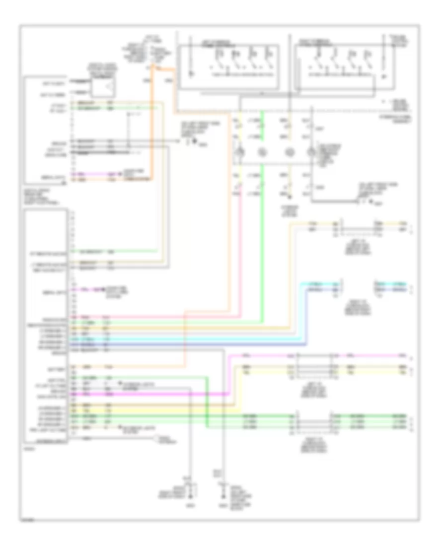
RADIO
Radio Wiring Diagram, with Amplifier (1 of 2) for Pontiac Grand Am SC/T 2005
List of elements for Radio Wiring Diagram, with Amplifier (1 of 2) for Pontiac Grand Am SC/T 2005:
- (digital audio system s-band) digital radio antenna
- (on left front side of dash, near fuse block)
- (on left front side of dash,near fuse block) sp202
- A10
- A11
- A12
- Am/
- Amp ctrl
- Ant in (sat)
- Ant in (terr)
- Antenna input
- Aud out -
- B10
- B11
- B12
- Bare
- Battery
- C10
- C12
- C206
- C207
- Coax
- Computer data lines system
- Cruise control system
- Digital radio receiver (if equipped) (right kick panel)
- Drain wire
- Exterior lights system
- G201
- G202
- G203
- Gain cntrl sig
- Ground
- Hot at all times
- I/p lmp voltage
- Inflatable restraint steering wheel module coil
- Interior lights system
- Left i/p fuse block (behind left side of dash)
- Left steering wheel controls
- Lf aud +
- Lf speaker (+)
- Lf speaker (-)
- Lr speaker (+)
- Lr speaker (-)
- Lt remote aud sig
- Mute
- Nca
- Play
- Pnk
- Pre-
- Prk lamp voltage
- Radio
- Radio antenna
- Radio battery fuse 15a
- Radio on sig
- Rem aud sig out -
- Remote radio cntrl
- Rf speaker (+)
- Rf speaker (-)
- Right i/p fuse block (behind right side of dash)
- Right steering wheel controls
- Rr speaker (+)
- Rr speaker (-)
- Rt aud +
- Rt remote aud sig
- Seek dn
- Seek up
- Serial data
- Set
- Sp201
- Sp202 (on left front side of dash, near fuse block)
- Sp203 (right front side of dash)
- Steering wheel assembly
- Tan
- Up vol
- Vol dn
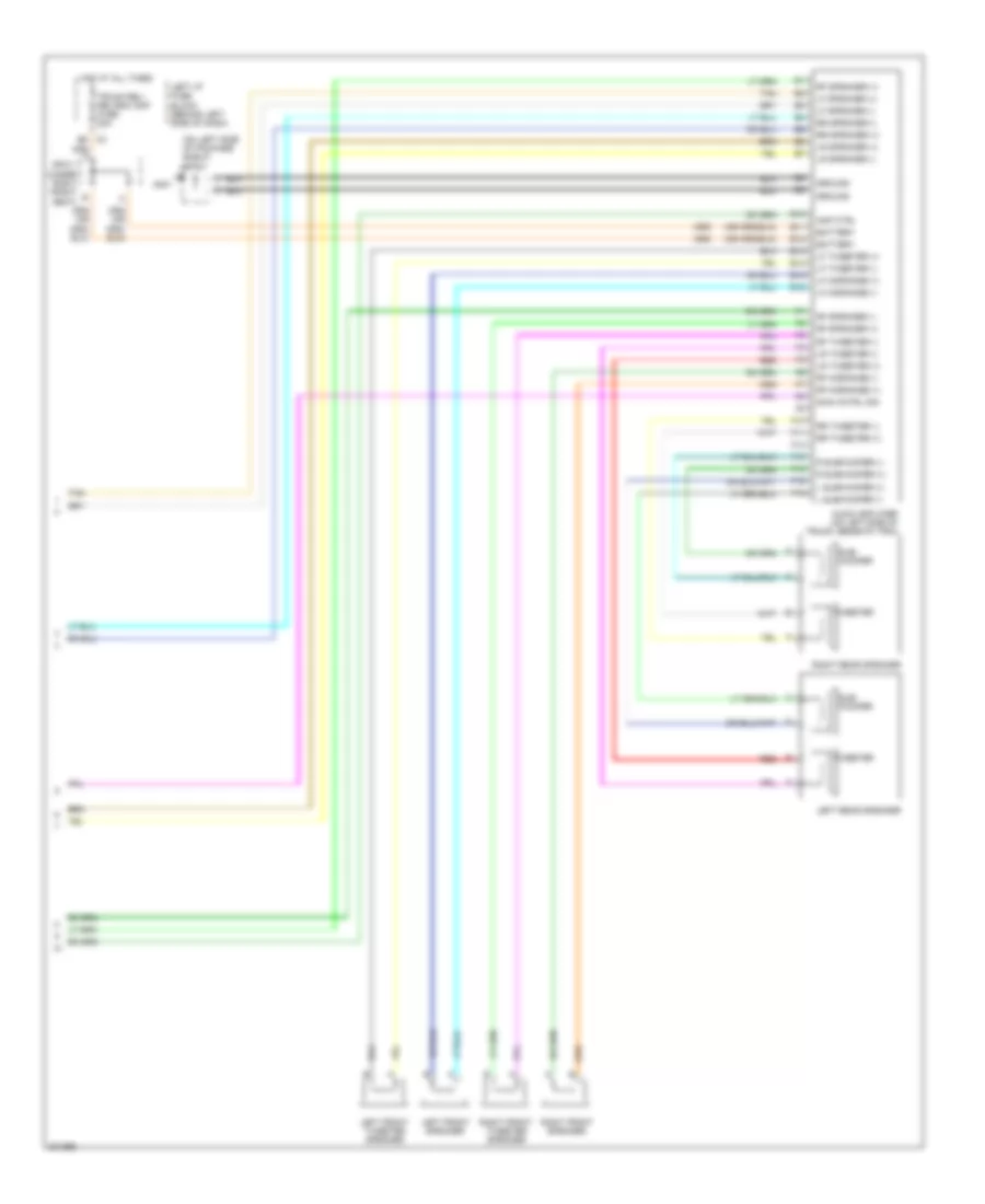
Radio Wiring Diagram, with Amplifier (2 of 2) for Pontiac Grand Am SC/T 2005
List of elements for Radio Wiring Diagram, with Amplifier (2 of 2) for Pontiac Grand Am SC/T 2005:
- (on left side of package shelf) sp401
- Amp ctrl
- Audio amplifier (on left side of trunk, beneath trim)
- B5 c3
- Battery
- E10
- E11
- E12
- E13
- E14
- E15
- E16
- F10
- F11
- F12
- F13
- F14
- F15
- F16
- G401
- Gain cntrl sig
- Ground
- Hot at all times
- L subwoofer (+)
- L subwoofer (-)
- Left front speaker
- Left front tweeter speaker
- Left i/p fuse block (behind left side of dash)
- Left rear speaker
- Lf midrange (+)
- Lf midrange (-)
- Lf speaker (+)
- Lf speaker (-)
- Lf tweeter (+)
- Lf tweeter (-)
- Lr speaker (+)
- Lr speaker (-)
- Lr tweeter (+)
- Lr tweeter (-)
- R subwoofer (+)
- R subwoofer (-)
- Red
- Rf midrange (+)
- Rf midrange (-)
- Rf speaker (+)
- Rf speaker (-)
- Rf tweeter (-)
- Right front speaker
- Right front tweeter speaker
- Right rear speaker
- Rr speaker (+)
- Rr speaker (-)
- Rr tweeter (+)
- Rr tweeter (-)
- Sp311 (under right front seat)
- Sub- woofer
- Tan
- Trunk rel/ rel/rdo amp fuse 20a
- Tweeter
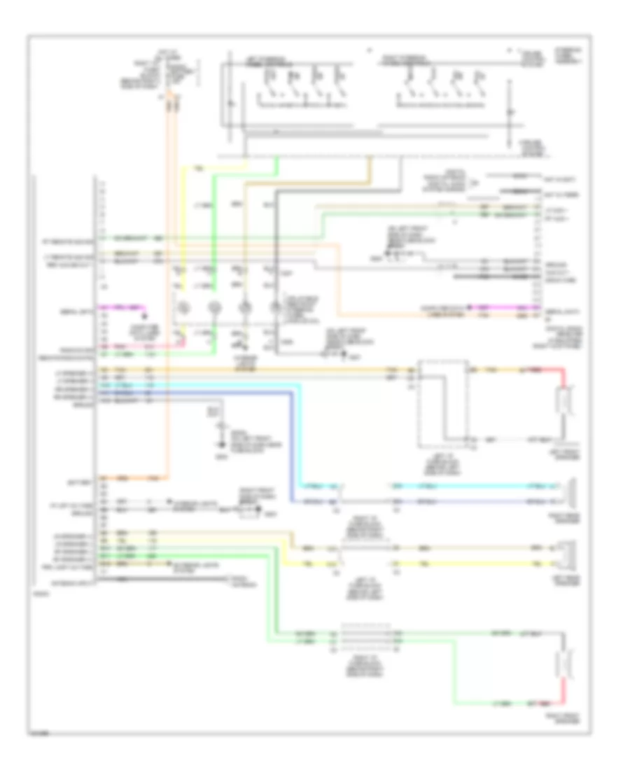
Radio Wiring Diagram, without Amplifier for Pontiac Grand Am SC/T 2005
List of elements for Radio Wiring Diagram, without Amplifier for Pontiac Grand Am SC/T 2005:
- (on left front side of dash, near fuse block) sp201
- (on left front side of dash, near fuse block) sp202
- (right front side of dash) sp203
- A10
- A11
- A12
- Am/
- Ant in (sat)
- Ant in (terr)
- Antenna input
- Aud out -
- B10
- B11
- B12
- Bare
- Battery
- C10
- C12
- C206
- C207
- Coax
- Computer data lines system
- Cruise control system
- Digital radio antenna (digital audio system s-band)
- Digital radio receiver (if equipped) (right kick panel)
- Dn vol
- Drain wire
- Exterior lights system
- G201
- G202
- G203
- Ground
- Hot at all times
- I/p lmp voltage
- Inflatable restraint steering wheel module coil
- Interior lights system
- Left front speaker
- Left i/p fuse block (behind left side of dash)
- Left rear speaker
- Left steering wheel controls
- Lf aud +
- Lf speaker (+)
- Lf speaker (-)
- Lr speaker (+)
- Lr speaker (-)
- Lt remote aud sig
- Mute
- Nca
- Play
- Pnk
- Pre-
- Prk lamp voltage
- Radio
- Radio antenna
- Radio battery fuse 15a
- Radio on sig
- Red
- Rem aud sig out -
- Remote radio cntrl
- Rf speaker (+)
- Rf speaker (-)
- Right front speaker
- Right i/p fuse block (behind right side of dash)
- Right rear speaker
- Right steering wheel controls
- Rr speaker (+)
- Rr speaker (-)
- Rt aud +
- Rt remote aud sig
- Seek dn
- Serial data
- Set
- Sp202 (on left front side of dash,near fuse block)
- Steering wheel assembly
- Tan
- Up seek
- Vol up
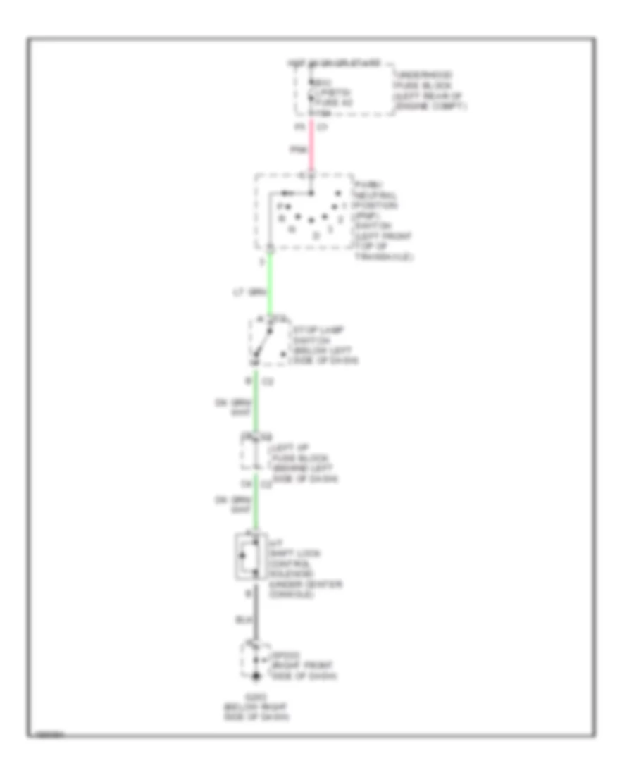
SHIFT INTERLOCK
Shift Interlock Wiring Diagram for Pontiac Grand Am SC/T 2005
List of elements for Shift Interlock Wiring Diagram for Pontiac Grand Am SC/T 2005:
- A/t shift lock control solenoid (under center console)
- B/u lp/btsi fuse 42 15a
- G203 (below right side of dash)
- Hot in on or start
- Left i/p fuse block (behind left side of dash) c2
- Park/ neutral position (pnp) switch (left front top of transaxle)
- Pnk
- Sp203 (right front side of dash)
- Stop lamp switch (below left side of dash)
- Underhood fuse block (left rear of engine compt)
STARTING/CHARGING
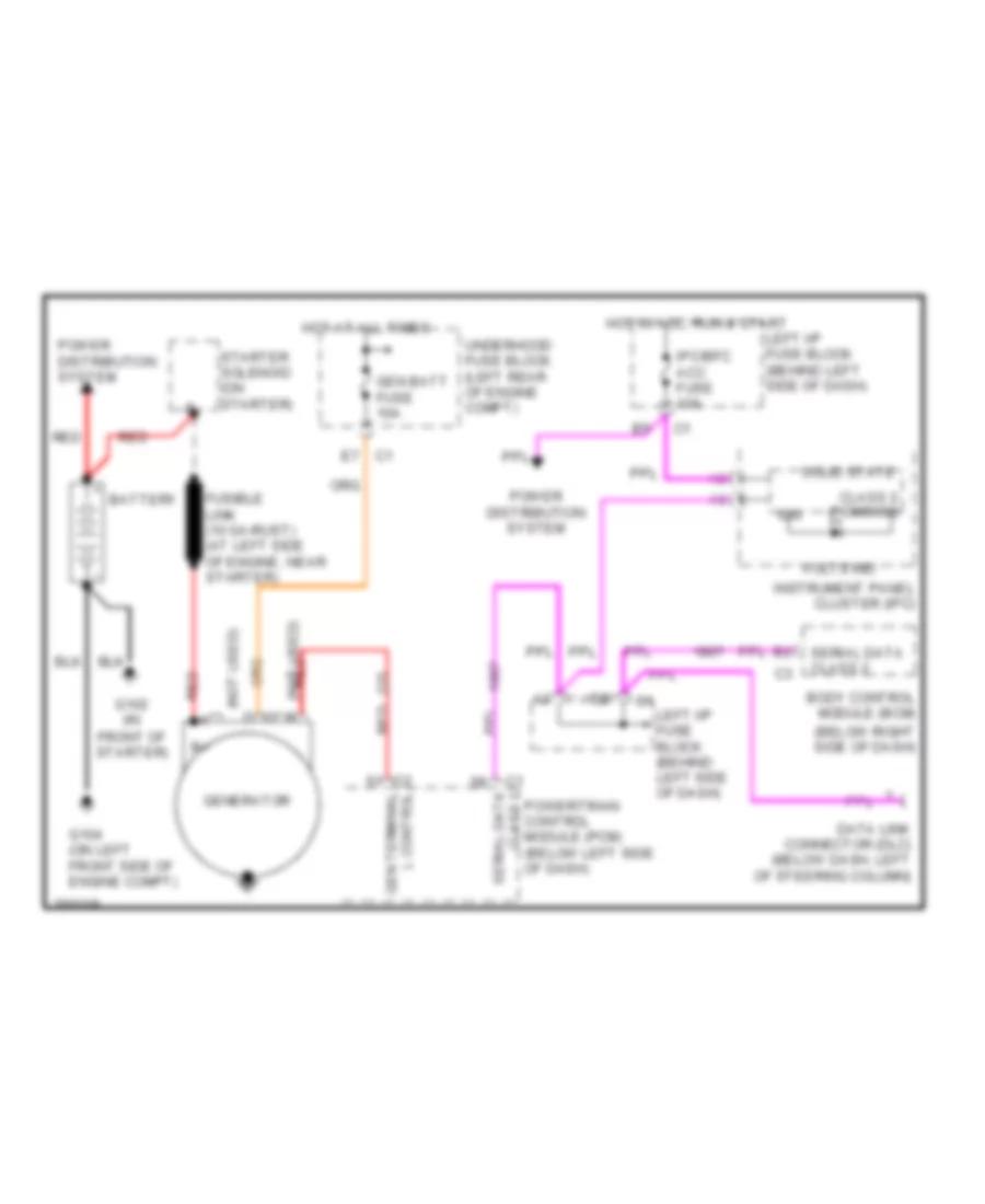
Charging Wiring Diagram for Pontiac Grand Am SC/T 2005
List of elements for Charging Wiring Diagram for Pontiac Grand Am SC/T 2005:
- (below right side of dash)
- (not used) c
- A (not used)
- Battery
- Body control module (bcm)
- C1 e7
- C1 left i/p fuse block (behind left side of dash)
- Class 2 (pcm/bcm)
- Data link connector (dlc) (below dash, left of steering column)
- Fusible link (10 ga-rust) (at left side of engine, near starter)
- G102 (in front of starter)
- G104 (on left front side of engine compt)
- Gen batt fuse 10a
- Gen terminal l control
- Generator
- Hot at all times
- Hot in acc, run & start
- Ign
- Instrument panel cluster (ipc)
- Ipc/bfc acc fuse 10a
- Left i/p fuse block (behind left side of dash)
- Power distribution system
- Powertrain control module (pcm) (below left side of dash)
- Red
- Serial data class 2
- Solid state
- Starter solenoid (on starter)
- Underhood fuse block (left rear of engine compt)
- Volts ind
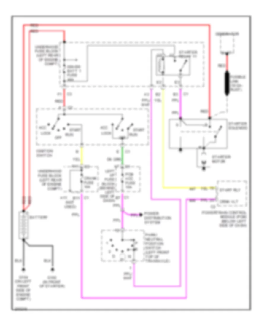
Starting Wiring Diagram for Pontiac Grand Am SC/T 2005
List of elements for Starting Wiring Diagram for Pontiac Grand Am SC/T 2005:
- (not used)
- A11
- Acc
- Batt
- Battery
- C1 b11
- C1 b7
- Crank fuse 10a
- Crnk vlt
- F11
- Fusible link (10 ga- rust)
- G102 (in front of starter)
- G104 (on left front side of engine compt)
- Generator
- Ign-sw batt 1 fuse 40a
- Ignition switch
- Left i/p fuse block (behind left side of dash)
- Lock
- Off
- Park/ neutral position switch (left front top of transaxle)
- Pcm acc fuse 10a
- Power distribution system
- Powertrain control module (pcm) (below left side of dash)
- Red
- Run
- Start
- Start rly
- Starter motor
- Starter relay 11
- Starter solenoid
- Underhood fuse block (left rear of engine compt)
SUPPLEMENTAL RESTRAINTS
Supplemental Restraints Wiring Diagram for Pontiac Grand Am SC/T 2005
List of elements for Supplemental Restraints Wiring Diagram for Pontiac Grand Am SC/T 2005:
- A10
- A11
- A12
- A13
- A14
- A15
- A16
- A17
- A18
- Air bag fuse e 10a
- Air bag indicator
- Anti-lock brakes system
- Body control module (bcm) (behind right side of dash)
- Case ground
- Class 2
- Class 2 serial data
- Class 2 serial data primary
- Data link connector (dlc) (below dash, left of steering column)
- Engine controls system
- High control
- Hot in on or start
- Ign
- Ignition
- Inflatable restraint i/p module (right side of instrument panel)
- Inflatable restraint sensing & diagnostic module (sdm) (under right front seat, below carpet)
- Inflatable restraint steering wheel module (center of steering wheel)
- Inflatable restraint steering wheel module coil
- Instrument panel cluster (ipc)
- Left i/p fuse block (behind left side of dash)
- Logic
- Low control
- Nca
- Serial data
- Shorting bar
TRANSMISSION
2.2L VIN F
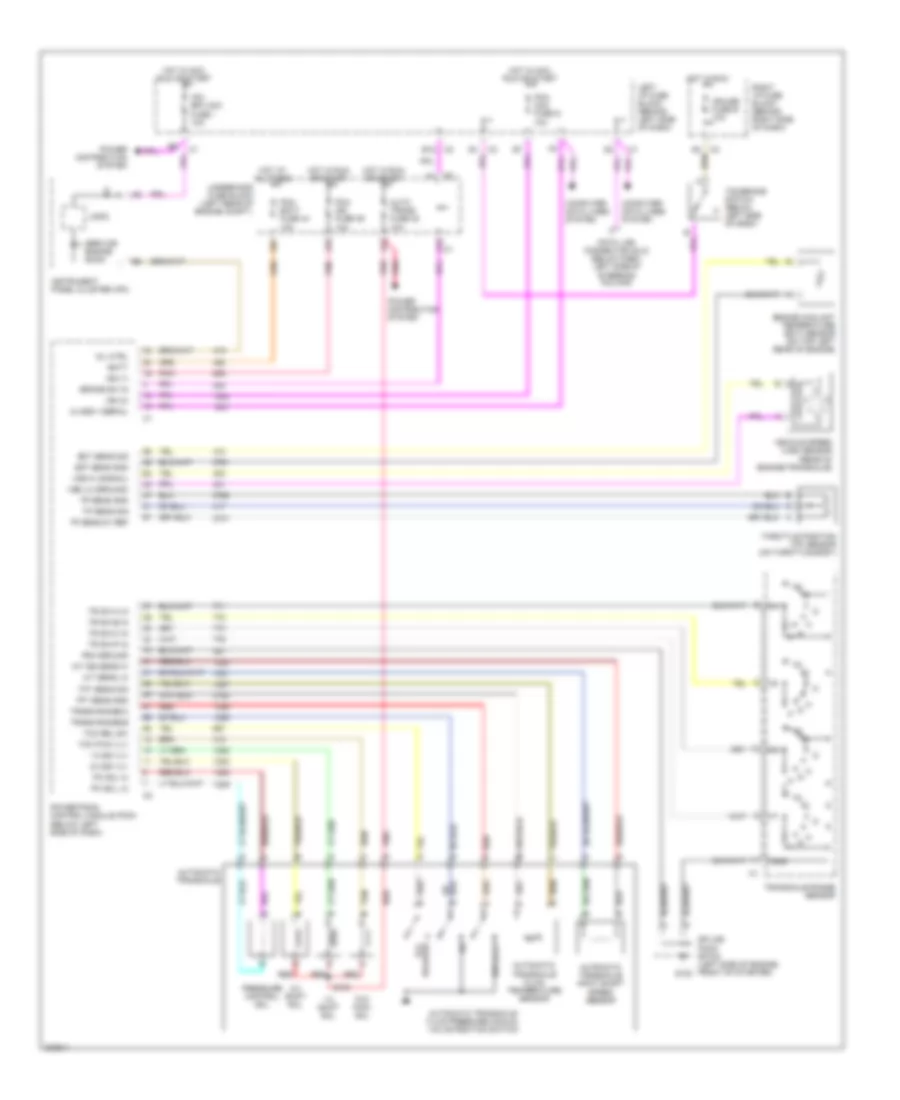
2.2L VIN F, A/T Wiring Diagram for Pontiac Grand Am SC/T 2005
List of elements for 2.2L VIN F, A/T Wiring Diagram for Pontiac Grand Am SC/T 2005:
- 1-2 shift sol
- 1-2 ss vlv
- 2-3 shift sol
- 2-3 ss vlv
- A/t iss sens hi
- A/t sens lo
- Auto trans fuse 38 10a
- Automatic transaxle
- Automatic transaxle fluid pressure manual valve position switch
- Automatic transaxle fluid temperature sensor
- Automatic transaxle input shaft speed sensor
- B12
- Batt
- Brake sw in
- Class ii serial
- Computer data lines system
- Cruise fuse e 10a
- Data link connector (dlc) (below dash, left side of steering column)
- Ect sens gnd
- Ect sens sig
- Engine coolant temperature (ect) sensor (on top left rear of engine)
- G102
- Gnd
- Hot at all times
- Hot in acc, run or start
- Hot in run
- Hot in run or start
- Ign (0)
- Ign (1)
- Instrument panel cluster (ipc)
- Ipc/ bfc acc fuse i 10a
- Left i/p fuse block (behind left side of dash)
- Logic
- Mil ctrl
- Pc sol hi
- Pc sol lo
- Pcm acc fuse g 10a
- Pcm batt fuse 44 10a
- Pcm ground
- Pcm ign fuse 39 10a
- Pnk
- Power distribution system
- Powertrain control module (pcm) (below left side of dash)
- Pressure control sol
- Red
- Release tcc
- Rev,d,2,1
- Right i/p fuse block (behind right side of dash)
- S103
- Service engine soon
- Splice pack sp102 (left side of engine, front of starter)
- Tan
- Tcc pwm sol
- Tcc pwm vlv
- Tcc rel sw
- Tcc/brake switch (below left side of dash)
- Tft sens gnd
- Tft sens sig
- Throttle position (tp) sensor (on throttle body)
- Tp sens 5v ref
- Tp sens gnd
- Tp sens sig
- Tr sw-a in
- Tr sw-b in
- Tr sw-c in
- Tr sw-p in
- Trans range-b
- Trans range-c
- Transaxle range sensor
- Underhood fuse block (left rear of engine compt.)
- Vehicle speed (vss) sensor (rear of engine/transaxle)
- Vss hi (signal)
- Vss lo (ground)
3.4L VIN E
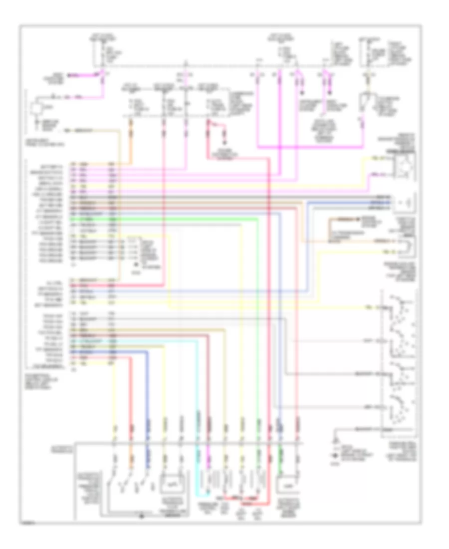
3.4L VIN E, A/T Wiring Diagram for Pontiac Grand Am SC/T 2005
List of elements for 3.4L VIN E, A/T Wiring Diagram for Pontiac Grand Am SC/T 2005:
- (in transmission harness) s102
- (rear of engine/transaxle assembly) vehicle speed sensor
- 1-2 shift sol
- 2-3 shift sol
- A/t sensor hi
- A/t sensor lo
- Auto trans fuse 38 10a
- Automatic transaxle
- Automatic transaxle fluid pressure manual valve position switch
- Automatic transaxle fluid temperature sensor
- Automatic transaxle input shaft speed sensor
- B12
- Battery in
- Body computer system
- Brake switch in
- C3 a9
- Cruise fuse e 10a
- Data link connector (below dash, left of steering column)
- Ect return
- Ect sensor in
- Engine controls system
- Engine coolant temperature sensor (top left rear of engine)
- G102
- Gnd
- Hot at all times
- Hot in acc, run or start
- Hot in run
- Hot in run or start
- Ignition (1) in
- Ignition (2) in
- Instrument cluster system
- Instrument panel cluster (ipc)
- Ipc/ bfc acc fuse i 10a
- Left i/p fuse block (behind left side of dash)
- Logic
- Mil ctrl
- Park/neutral position (pnp) switch (left front top of transaxle)
- Pc sol hi
- Pc sol lo
- Pcm acc fuse g 10a
- Pcm batt fuse 44 10a
- Pcm ground
- Pcm ign fuse 39 10a
- Pnk
- Power distribution system
- Powertrain control module (below left side of dash)
- Pressure control sol
- Red
- Rev
- Right i/p fuse block (behind right side of dash)
- S103
- Serial data
- Service engine soon
- Sp102 (left side of engine, in front of starter)
- Tan
- Tcc
- Tcc pwm sol
- Tcc release in
- Tcc/brake switch (below left side of dash)
- Tfp sw b
- Tfp sw c
- Tft sensor gnd
- Tft sensor in
- Throttle position sensor (on throttle body)
- Tp 5v ref
- Tp sensor in
- Tps return
- Tr sw in-a
- Tr sw in-b
- Tr sw in-c
- Tr sw in-p
- Underhood fuse block (left rear of engine compt)
- Vss hi (signal)
- Vss lo (ground)
TRUNK, TAILGATE, FUEL DOOR
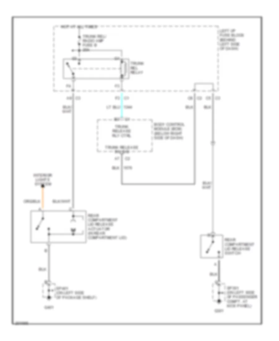
Trunk Release Wiring Diagram for Pontiac Grand Am SC/T 2005
List of elements for Trunk Release Wiring Diagram for Pontiac Grand Am SC/T 2005:
- A9 c3
- Body control module (bcm) (below right side of dash)
- C5 c3
- C8 c2
- F3 c1
- G301
- G401
- Hot at all times
- Interior lights system
- Left i/p fuse block (behind left side of dash)
- Rear compartment lid release actuator (in rear compartment lid)
- Rear compartment lid release switch
- Sp301 (on left side of passenger compt, at kick panel)
- Sp401 (on left side of package shelf)
- Trunk rel relay
- Trunk rel/ radio amp fuse b 20a
- Trunk release rly ctrl
- Trunk release sw sig
WARNING SYSTEMS
Warning Systems Wiring Diagram for Pontiac Grand Am SC/T 2005
List of elements for Warning Systems Wiring Diagram for Pontiac Grand Am SC/T 2005:
- A/c bfc fuse 37 10a
- A10
- A11
- A12
- A8 c2
- B10
- B11
- B12
- Battery
- Bfc batt fuse f 10a
- Body control module (bcm) (below right side of dash)
- C1 a2
- C1 d2
- C1 e7
- C2 b4
- C2 c2
- C3 b12
- C3 b9
- C3 c4
- Class 2 (bcm)
- Class 2 serial data
- Coolant level switch (closed w/ low fluid level) (in right side of engine compt)
- Courtesy lamps volt
- Ctsy lamps low ctrl
- Data link connector (dlc) (below dash, left of steering column)
- Dr lock/unlock sig
- Driver door ajar sig
- Driver unlock door lock switch
- Front unlock pass- enger door lock switch
- G101
- G202
- G301
- G302
- Ground
- Head
- Hot at all times
- Hot in on or start
- Ign
- Ignition 1 voltage
- Ignition switch (key warning switch)
- Instrument panel cluster (ipc)
- Int lps fuse g 10a
- Interior lights system
- Key in ignition sw
- Left front door jamb switch
- Left i/p fuse block (behind left side of dash)
- Left rear door ajar switch (sedan) (left "b"pillar)
- Left seat belt sw
- Lock
- Logic
- Low coolant level ind
- Nca
- Off
- Park
- Park brake sw signal
- Park brake switch (part of park brake assembly)
- Park lamp on signal
- Park lps fuse 45 15a
- Pass door ajar sw sig
- Pnk
- Powertrain control module (pcm) (below left side of dash)
- Radio
- Right front door jamb switch
- Right i/p fuse block (behind right side of dash)
- Right rear door ajar switch (sedan) (left "b" pillar)
- Seat belt ind
- Seat belt switch (part of driver's seat belt buckle)
- Serial data
- Sp101 (on left side of engine compt, near strut)
- Sp202 (on left front side of dash, near fuse block)
- Sp301 (on left side of passenger compt, at kick panel)
- Sp302 (right front rocker panel)
- Turn signal/ multi-function switch
- Underhood fuse block (left rear of engine compt)
- Washer level signal
- Windshield washer fluid level switch (closed w/ low fluid level)
WIPER/WASHER
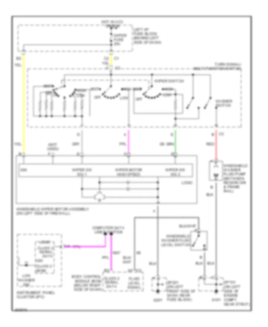
Wiper/Washer Wiring Diagram for Pontiac Grand Am SC/T 2005
List of elements for Wiper/Washer Wiring Diagram for Pontiac Grand Am SC/T 2005:
- (not used)
- Body control module (bcm) (below right side of dash)
- C3 a6
- Class 2 (bcm)
- Class 2 serial data
- Computer data lines system
- Fluid level signal
- G101
- G201
- High
- Hot in acc or run
- Ign
- Instrument panel cluster (ipc)
- Left i/p fuse block (behind left side of dash)
- Logic
- Low
- Low washer ind
- Mist
- Off
- Red
- Sp101 (on left side of engine compt, near strut)
- Sp201 (on left front side of dash, near fuse block)
- Turn signal/ multi-function switch
- Washer switch
- Windshield washer fluid level switch
- Windshield washer fluid pump (between reservoir & frame rail)
- Windshield wiper motor assembly (on left side of firewall)
- Wiper fuse 25a
- Wiper motor high speed
- Wiper sw sig 1
- Wiper sw sig 2
- Wiper switch

 Čeština
 Dansk
Dansk Deutsch
 Ελληνικά
 English
 English
 Suomi
Suomi Français
 Français
 עברית
עברית Hrvatski
 Magyar
 Italiano
 日本語
日本語 한국어
한국어 Nederlands
 Polski
 Português
 Português
 Română
 Русский
 Slovenčina
 Slovenščina
 Svenska
 Türkçe
 中文 (中国)