EXTERIOR LIGHTS
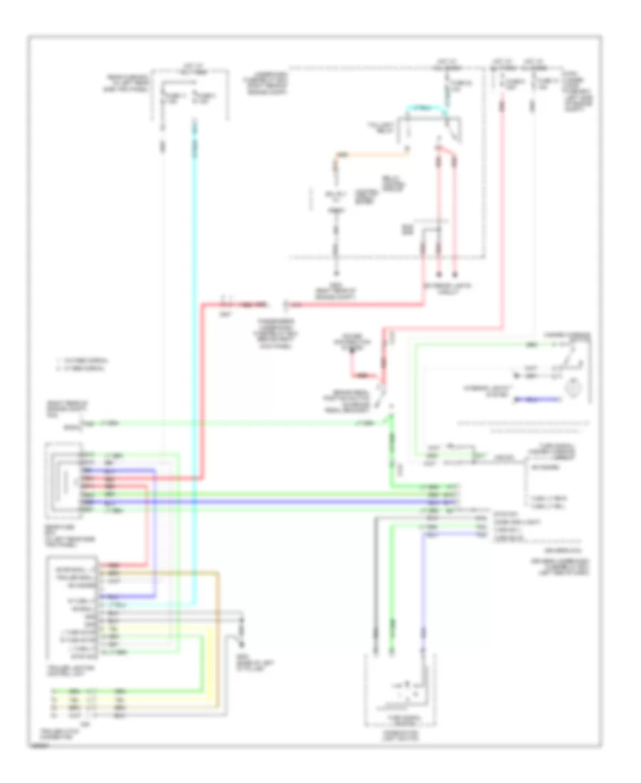
Backup Lamps Wiring Diagram for Honda Odyssey Touring 2013

List of elements for Backup Lamps Wiring Diagram for Honda Odyssey Touring 2013:
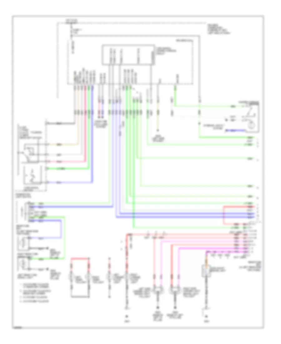
Exterior Lamps Wiring Diagram (1 of 2) for Honda Odyssey Touring 2013
List of elements for Exterior Lamps Wiring Diagram (1 of 2) for Honda Odyssey Touring 2013:
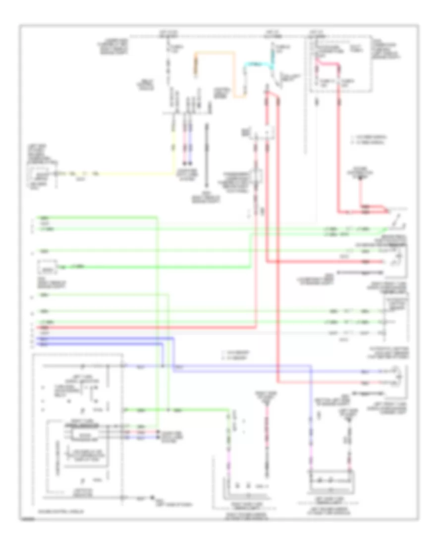
Exterior Lamps Wiring Diagram (2 of 2) for Honda Odyssey Touring 2013
List of elements for Exterior Lamps Wiring Diagram (2 of 2) for Honda Odyssey Touring 2013:
Trailer Tow Wiring Diagram for Honda Odyssey Touring 2013
List of elements for Trailer Tow Wiring Diagram for Honda Odyssey Touring 2013: