EXTERIOR LIGHTS
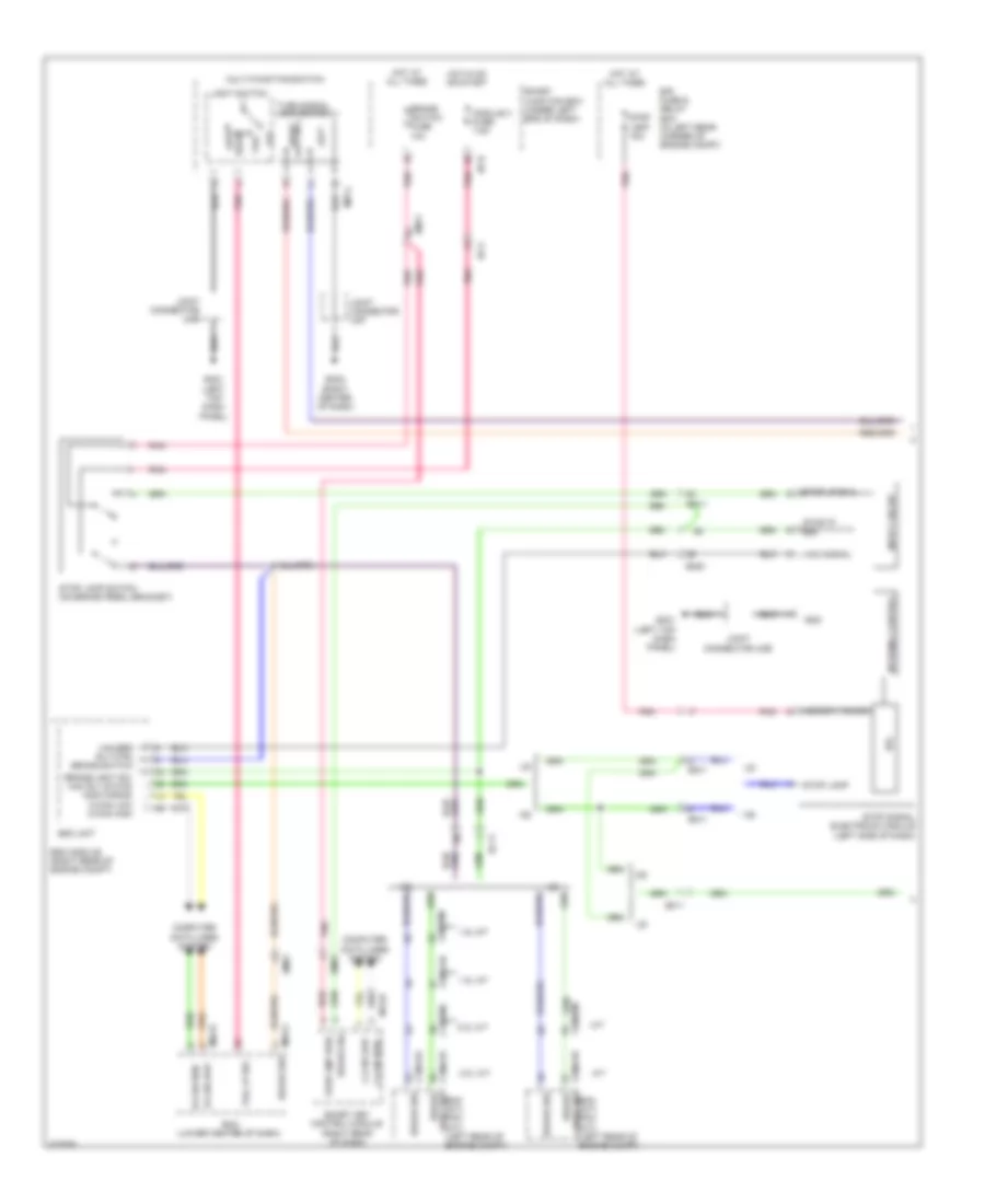
Backup Lamps Wiring Diagram for Hyundai Elantra Sport 2014

List of elements for Backup Lamps Wiring Diagram for Hyundai Elantra Sport 2014:
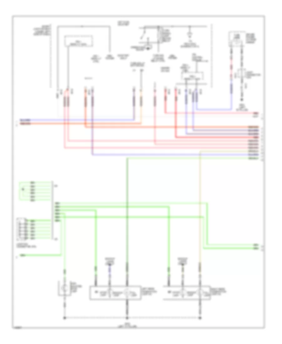
Exterior Lamps Wiring Diagram (1 of 4) for Hyundai Elantra Sport 2014
List of elements for Exterior Lamps Wiring Diagram (1 of 4) for Hyundai Elantra Sport 2014:
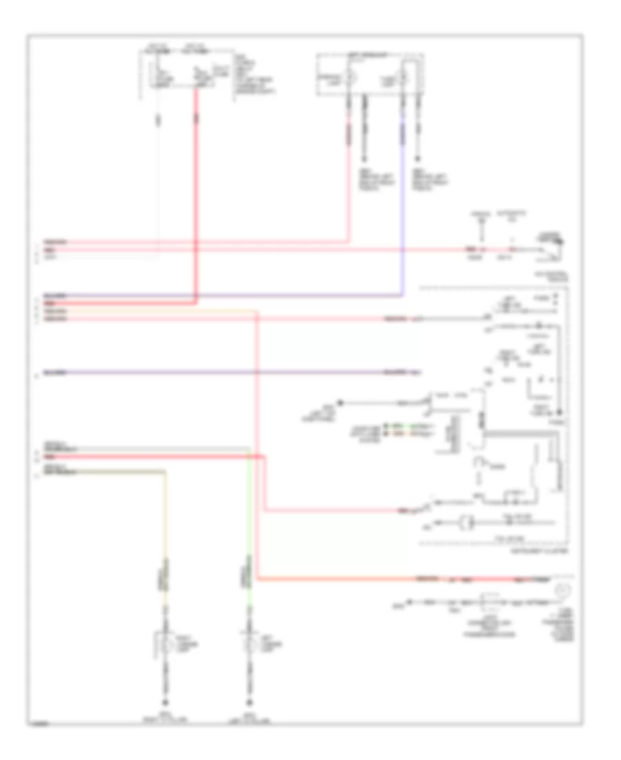
Exterior Lamps Wiring Diagram (2 of 4) for Hyundai Elantra Sport 2014
List of elements for Exterior Lamps Wiring Diagram (2 of 4) for Hyundai Elantra Sport 2014:
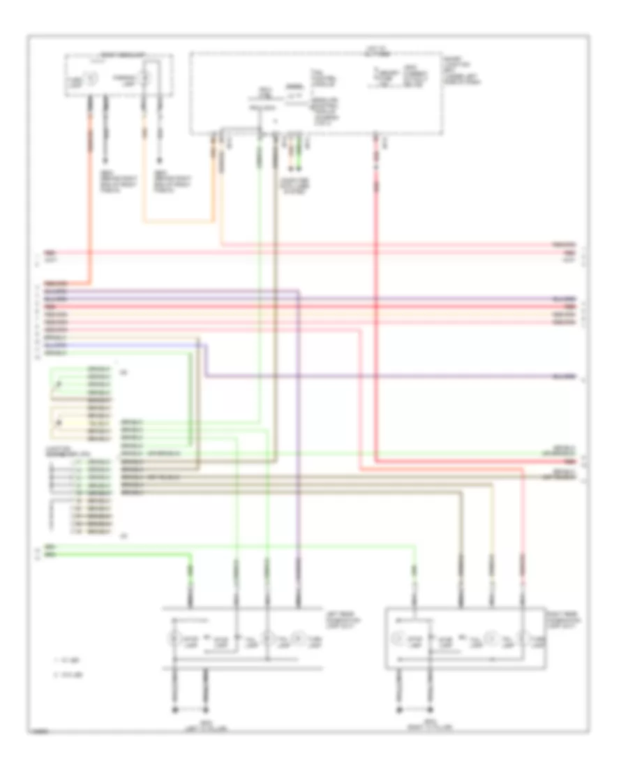
Exterior Lamps Wiring Diagram (3 of 4) for Hyundai Elantra Sport 2014
List of elements for Exterior Lamps Wiring Diagram (3 of 4) for Hyundai Elantra Sport 2014:
Exterior Lamps Wiring Diagram (4 of 4) for Hyundai Elantra Sport 2014
List of elements for Exterior Lamps Wiring Diagram (4 of 4) for Hyundai Elantra Sport 2014: