EXTERIOR LIGHTS
Back-up Lamps Wiring Diagram for Mitsubishi Lancer ES 2007

List of elements for Back-up Lamps Wiring Diagram for Mitsubishi Lancer ES 2007:
- (behind instrument cluster) joint connector 2
- A/t
- Back-up light switch (on top of transaxle)
- C210
- G8 (at rear shelf panel)
- G9 (at rear shelf panel)
- Hot in on or start
- Junction block (behind left end of dash)
- Left back-up light
- Left rear combination light assembly
- M/t
- Multi- purpose fuse 3 7.5a
- Nca
- Red
- Right back-up light
- Right rear combination light assembly
- Transmission range switch (left front of engine compt)
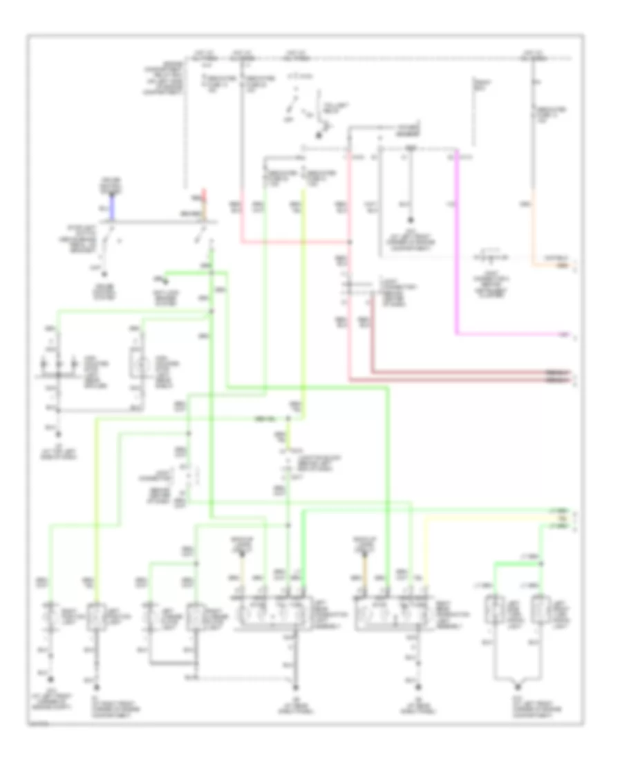
Exterior Lamps Wiring Diagram (1 of 2) for Mitsubishi Lancer ES 2007
List of elements for Exterior Lamps Wiring Diagram (1 of 2) for Mitsubishi Lancer ES 2007:
- A10x
- A11x
- Anti-lock brakes system
- Back-up lamps circuit
- C210
- C217
- Cruise control system
- Dedicated fuse 10 15a
- Dedicated fuse 13 10a
- Dedicated fuse 20 7.5a
- Dedicated fuse 21 7.5a
- Dedicated fuse 22 10a
- Engine compartment relay box (on left side of engine compartment)
- Front ecu
- G1 (at right front corner of engine compartment)
- G13 (at left front corner of engine compartment)
- G13 (at left front corner of engine compt)
- G7 (at top left side of dash)
- G8 (at rear shelf panel)
- G9 (at rear shelf panel)
- Gnd
- High mounted stop light (rear shelf)
- High mounted stop light (rear spoiler)
- Hot at all times
- Joint connector (behind center of dash)
- Joint connector 1 (behind center of dash)
- Joint connector 2 (behind instrument cluster)
- Junction block (behind left end of dash)
- Left front turn signal light
- Left license plate light
- Left position light
- Left rear combination light assembly
- Left side turn signal light
- Nca
- Off
- Power source
- Red
- Right license plate light
- Right position light
- Right rear combination light assembly
- Stop
- Stoplight switch (above brake pedal, on bracket)
- Tail
- Taillight relay
- Turn
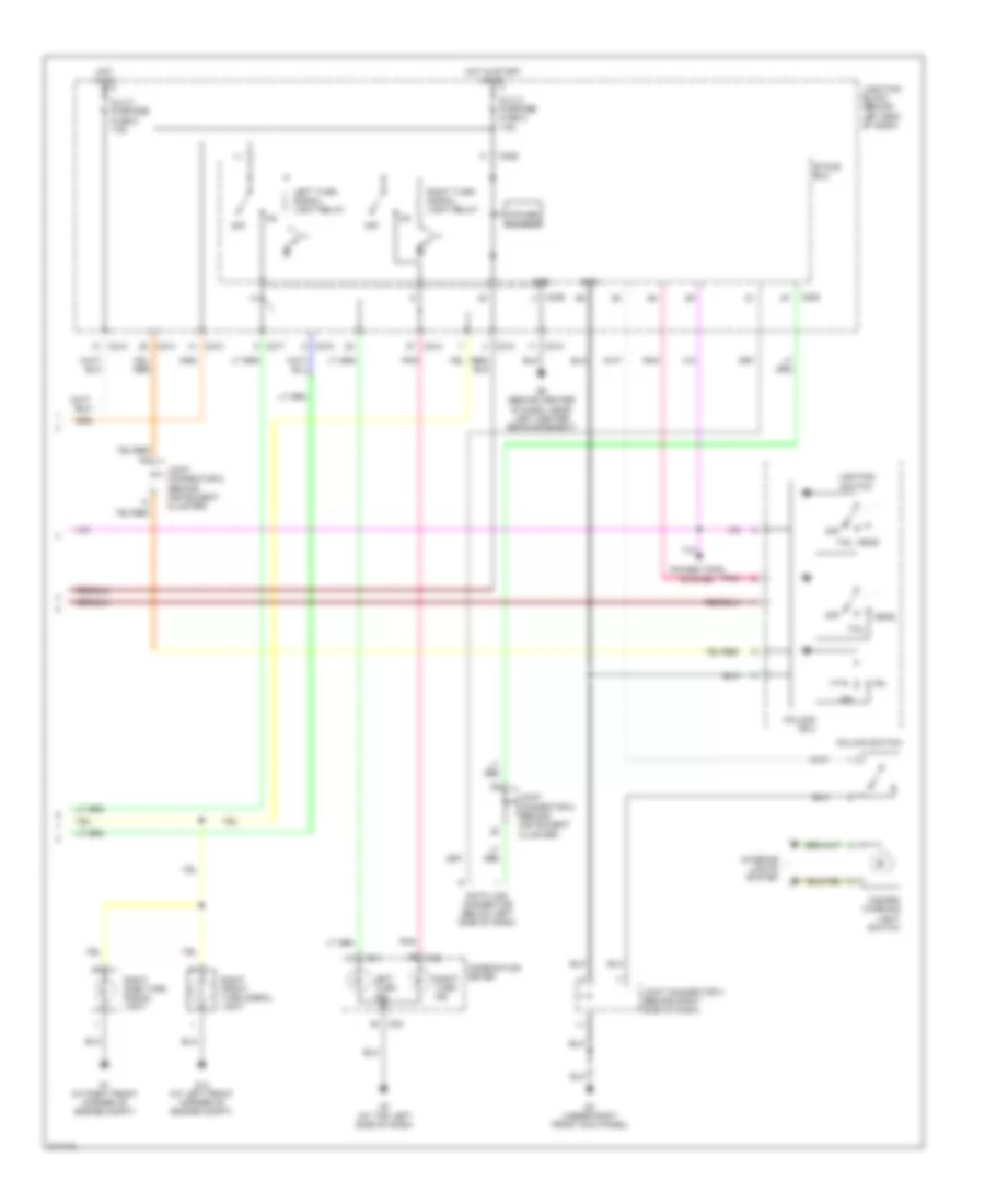
Exterior Lamps Wiring Diagram (2 of 2) for Mitsubishi Lancer ES 2007
List of elements for Exterior Lamps Wiring Diagram (2 of 2) for Mitsubishi Lancer ES 2007:
- C01
- C02
- C210
- C214
- C217
- C226
- C228
- Column ecu
- Column switch
- Combination meter
- Data link connector (below left side of dash)
- Etacs ecu
- G1 (at right front corner of engine compt)
- G13 (at left front corner of engine compt)
- G3 (under right front kick panel)
- G6 (behind center of dash, near left center reinforcement)
- G7 (at top left side of dash)
- Gnd
- Hazard warning light switch
- Head
- Hot in on
- Hot in start or on
- Interior lights system
- Joint connector 2 (behind instrument cluster)
- Joint connector 3 (behind right side of dash)
- Joint connector 5 (behind instrument cluster)
- Junction block (behind left end of dash)
- Left turn ind
- Left turn signal light relay
- Lighting switch
- Multi- purpose fuse 2 7.5a
- Multi- purpose fuse 5 7.5a
- Off
- Pnk
- Power source
- Power tops system
- Right front turn signal light
- Right side turn signal light
- Right turn ind
- Right turn signal light relay
- Tail