EXTERIOR LIGHTS
Back-up Lamps Wiring Diagram, Evolution for Mitsubishi Lancer LS 2004

List of elements for Back-up Lamps Wiring Diagram, Evolution for Mitsubishi Lancer LS 2004:
- Back-up light switch
- C210
- G8 (under rear seat back, at right upper corner of rear shelf panel)
- G9 (under rear seat back, at left upper corner of rear shelf panel)
- Hot in run or start
- Joint connector 4
- Junction block (behind left end of dash)
- Left back-up light
- Left rear combination light assembly
- Multi- purpose fuse 3 7.5a
- Nca
- Red
- Right back-up light
- Right rear combination light assembly
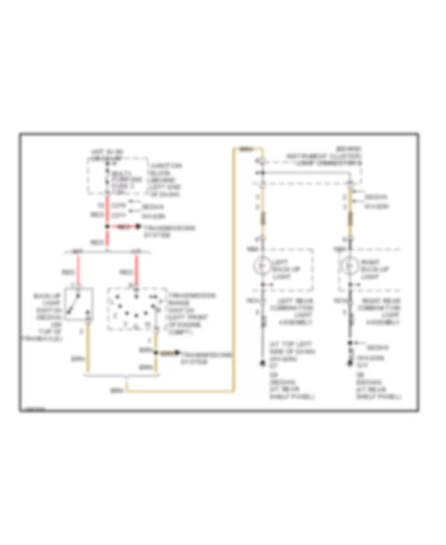
Back-up Lamps Wiring Diagram, Except Evolution for Mitsubishi Lancer LS 2004
List of elements for Back-up Lamps Wiring Diagram, Except Evolution for Mitsubishi Lancer LS 2004:
- (at top left side of dash) (wagon) g7
- (behind instrument cluster) joint connector 2
- (wagon) g17
- A/t
- Back-up light switch (sedan) (on top of transaxle)
- C210
- G8 (sedan) (at rear shelf panel)
- G9 (sedan) (at rear shelf panel)
- Hot in on or start
- Junction block (behind left end of dash)
- Left back-up light
- Left rear combination light assembly
- M/t
- Multi- purpose fuse 3 7.5a
- Nca
- Red
- Red c211
- Right back-up light
- Right rear combination light assembly
- Sedan
- Transmission range switch (left front of engine compt)
- Transmissions system
- Wagon
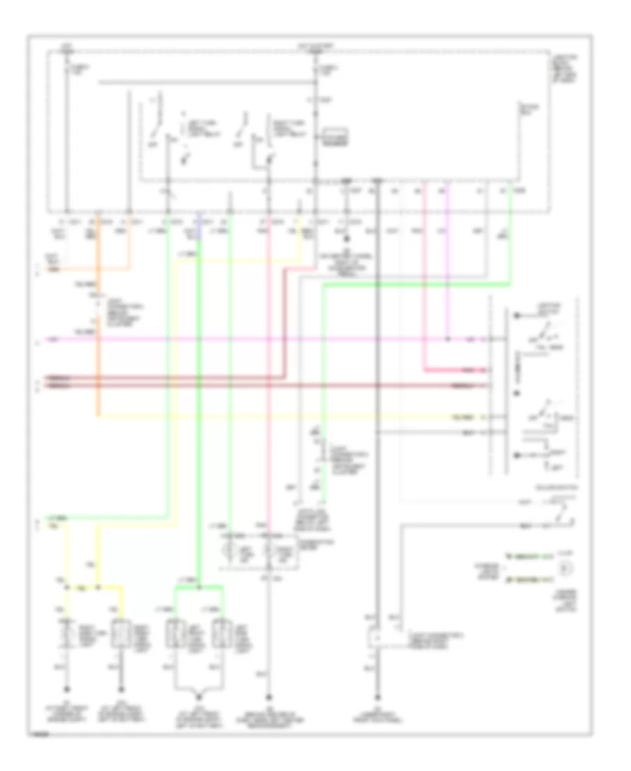
Exterior Lamps Wiring Diagram, Evolution (1 of 2) for Mitsubishi Lancer LS 2004
List of elements for Exterior Lamps Wiring Diagram, Evolution (1 of 2) for Mitsubishi Lancer LS 2004:
- (not used)
- A10x
- A11x
- Air conditioning system
- Anti-lock brakes system
- Anti-theft system
- Back-up lamps circuit
- C210
- C217
- Dedicated fuse 10 15a
- Dedicated fuse 13 10a
- Dedicated fuse 20 7.5a
- Dedicated fuse 21 7.5a
- Dedicated fuse 22 10a
- Engine compartment relay box (on left side of engine compartment)
- Front ecu
- G1 (at right front corner of engine compartment)
- G13 (at left front corner of engine compartment)
- G8 (under rear seat back, at right upper corner of rear shelf panel)
- G9 (under rear seat back, at left upper corner of rear shelf panel)
- Gnd
- Headlights system
- High mounted stop light
- Hot at all times
- Joint connector 1 (behind center of dash)
- Joint connector 2 (behind instrument cluster)
- Junction block (behind left end of dash)
- Left front combi- nation assembly
- Left license plate light
- Left rear combination light assembly turn
- Left rear side marker light
- Left side turn signal light
- Nca
- Off
- Position
- Power source
- Red
- Right license plate light
- Right rear combination light assembly turn
- Right rear side marker light
- Stop
- Stoplight switch (above brake pedal, on bracket)
- Tail
- Taillight relay
- Turn
- Vehicles w/ halogen headlights
- Vehicles w/ hid headlights
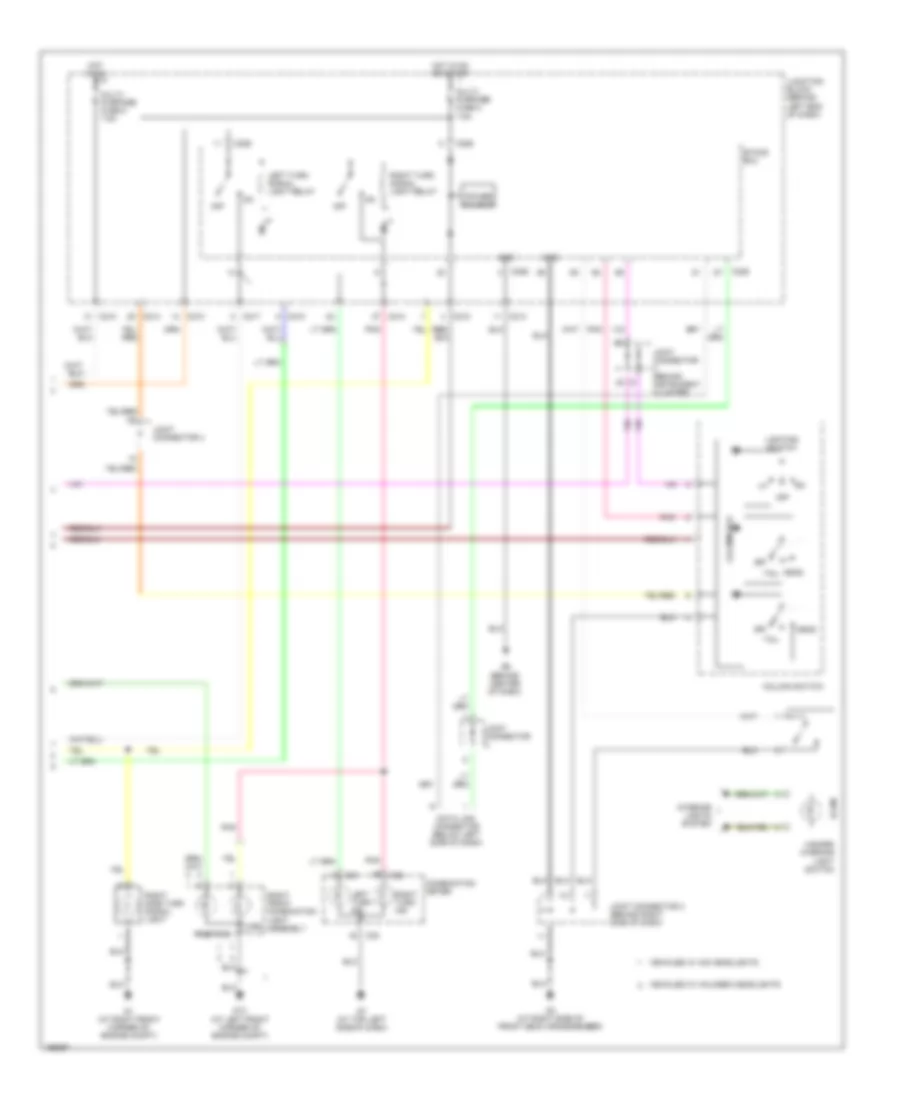
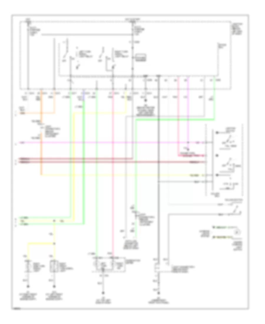
Exterior Lamps Wiring Diagram, Evolution (2 of 2) for Mitsubishi Lancer LS 2004
List of elements for Exterior Lamps Wiring Diagram, Evolution (2 of 2) for Mitsubishi Lancer LS 2004:
- C01
- C02
- C210
- C214
- C217
- C226
- C228
- Column switch
- Column-ecu
- Combination meter
- Data link connector (below left side of dash)
- Etacs ecu
- G1 (at right front corner of engine compt)
- G13 (at left front corner of engine compt)
- G3 (at right side of front deck crossmember)
- G6 (behind center of dash)
- G7 (at top left side of dash)
- Gnd
- Hazard warning light switch
- Head
- Hot in on
- Hot in on or start
- Illum
- Interior lights system
- Joint connector
- Joint connector (behind instrument cluster)
- Joint connector 3 (behind right side of dash)
- Joint connector 4
- Junction block (behind left end of dash)
- Left turn ind
- Left turn signal light relay
- Lighting switch
- Multi- purpose fuse 2 7.5a
- Multi- purpose fuse 5 7.5a
- Off
- Pnk
- Position
- Power source
- Right front combination light assembly
- Right side turn signal light
- Right turn ind
- Right turn signal light relay
- Tail
- Turn
- Vehicles w/ halogen headlights
- Vehicles w/ hid headlights
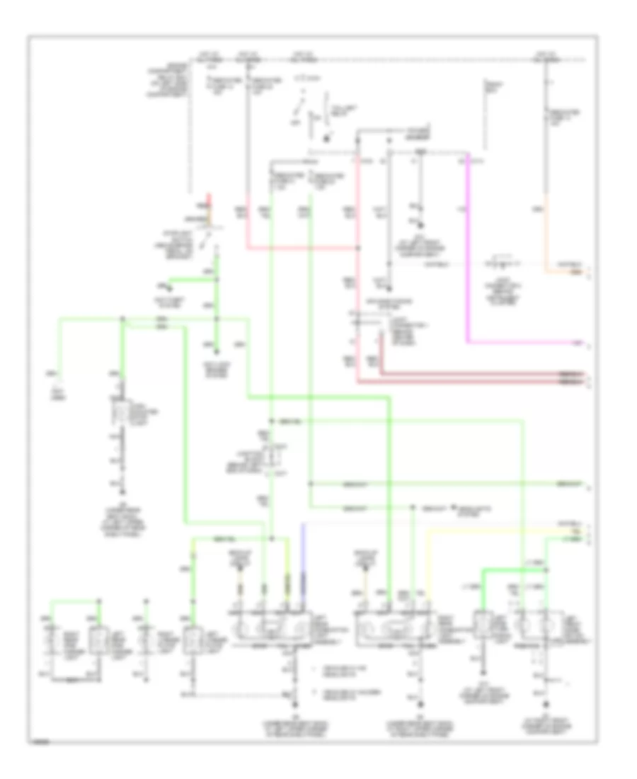
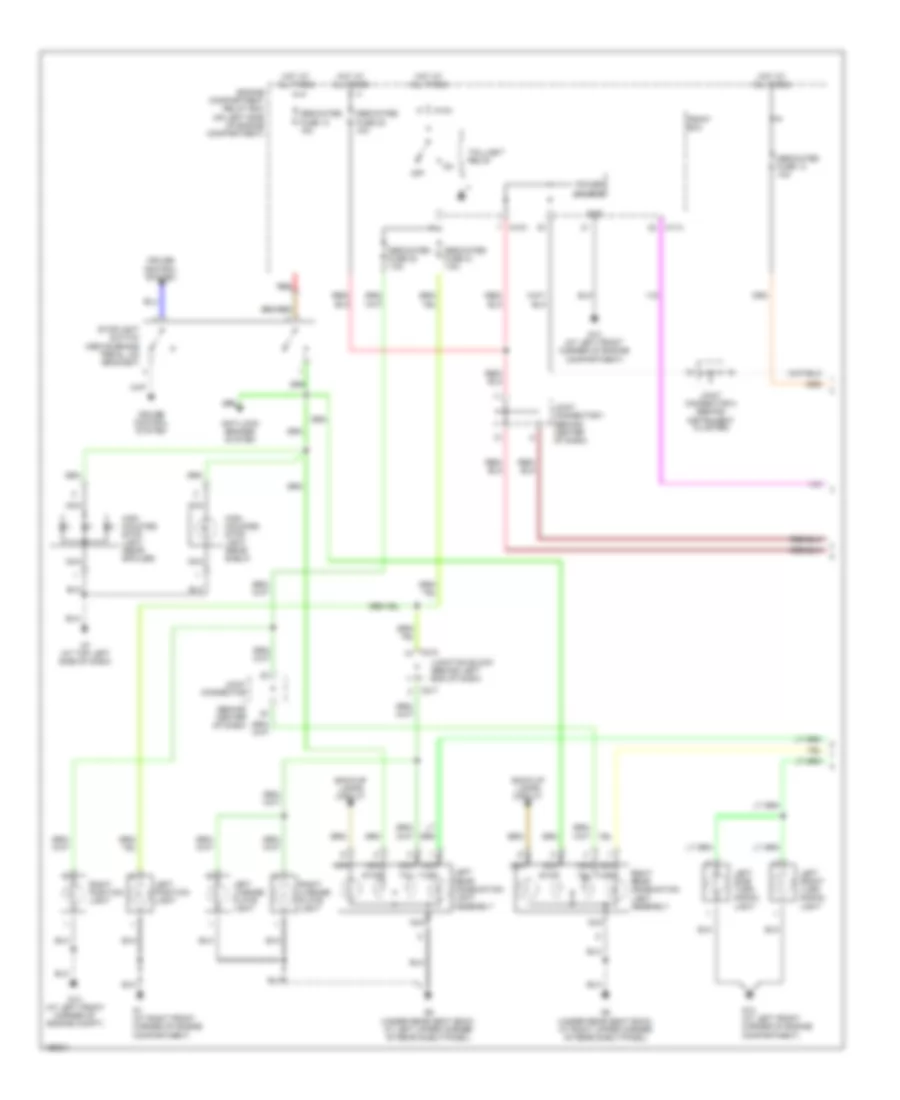
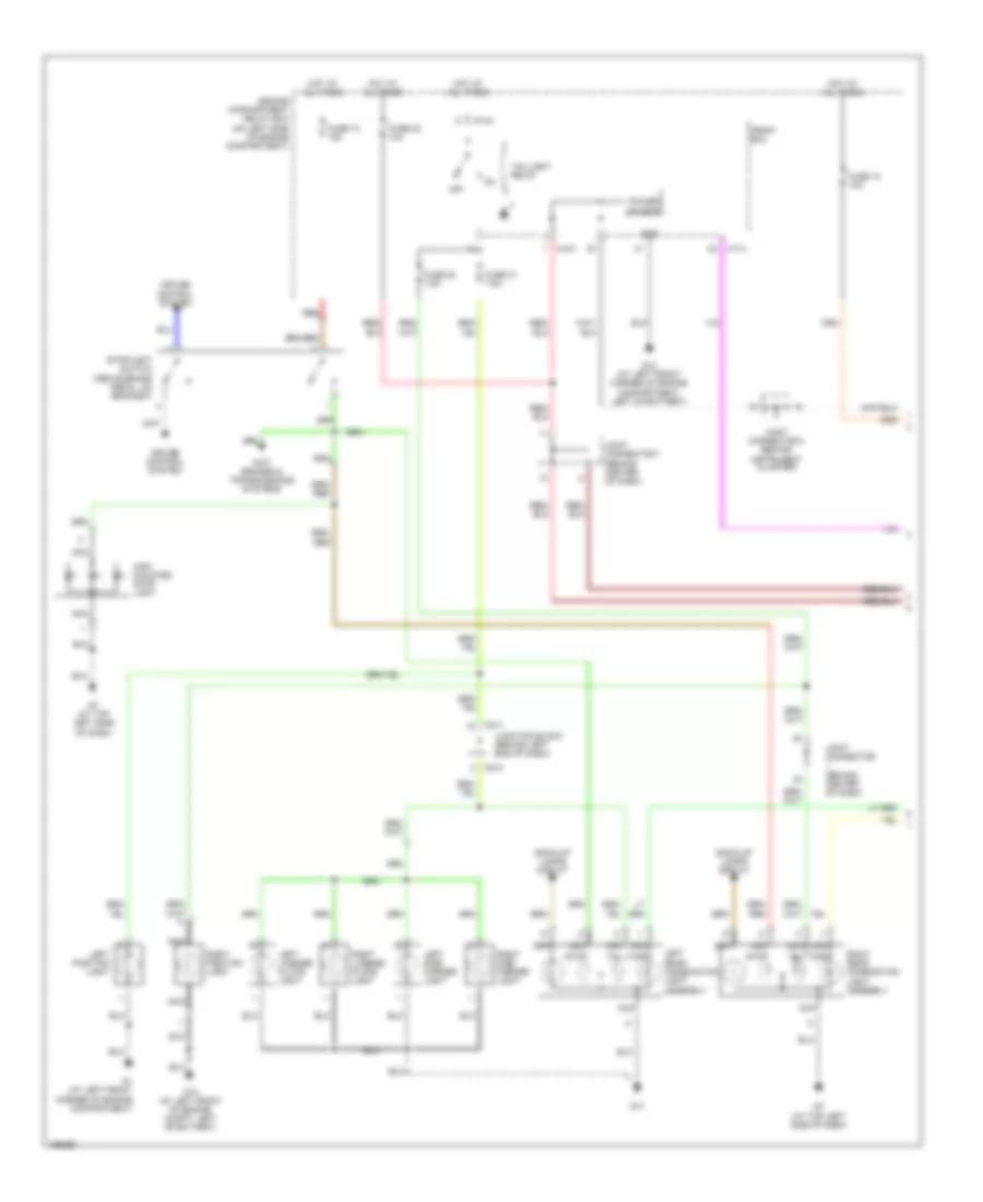
Exterior Lamps Wiring Diagram, Except Wagon or Evolution (1 of 2) for Mitsubishi Lancer LS 2004
List of elements for Exterior Lamps Wiring Diagram, Except Wagon or Evolution (1 of 2) for Mitsubishi Lancer LS 2004:
- A10x
- A11x
- Anti-lock brakes system
- Back-up lamps circuit
- C210
- C217
- Cruise control system
- Dedicated fuse 10 15a
- Dedicated fuse 13 10a
- Dedicated fuse 20 7.5a
- Dedicated fuse 21 7.5a
- Dedicated fuse 22 10a
- Engine compartment relay box (on left side of engine compartment)
- Front ecu
- G1 (at right front corner of engine compartment)
- G13 (at left front corner of engine compartment)
- G13 (at left front corner of engine compt)
- G7 (at top left side of dash)
- G8 (under rear seat back, at right upper corner of rear shelf panel)
- G9 (under rear seat back, at left upper corner of rear shelf panel)
- Gnd
- High mounted stop light (rear shelf)
- High mounted stop light (rear spoiler)
- Hot at all times
- Joint connector (behind center of dash)
- Joint connector 1 (behind center of dash)
- Joint connector 2 (behind instrument cluster)
- Junction block (behind left end of dash)
- Left front turn signal light
- Left license plate light
- Left position light
- Left rear combination light assembly
- Left side turn signal light
- Nca
- Off
- Power source
- Red
- Right license plate light
- Right position light
- Right rear combination light assembly
- Stop
- Stoplight switch (above brake pedal, on bracket)
- Tail
- Taillight relay
- Turn
Exterior Lamps Wiring Diagram, Except Wagon or Evolution (2 of 2) for Mitsubishi Lancer LS 2004
List of elements for Exterior Lamps Wiring Diagram, Except Wagon or Evolution (2 of 2) for Mitsubishi Lancer LS 2004:
- C01
- C02
- C210
- C214
- C217
- C226
- C228
- Column ecu
- Column switch
- Combination meter
- Data link connector (below left side of dash)
- Etacs ecu
- G1 (at right front corner of engine compt)
- G13 (at left front corner of engine compt)
- G3 (under right front kick panel)
- G6 (behind center of dash, near left center reinforcement)
- G7 (at top left side of dash)
- Gnd
- Hazard warning light switch
- Head
- Hot in on
- Hot in start or on
- Interior lights system
- Joint connector 2 (behind instrument cluster)
- Joint connector 3 (behind right side of dash)
- Joint connector 5 (behind instrument cluster)
- Junction block (behind left end of dash)
- Left turn ind
- Left turn signal light relay
- Lighting switch
- Multi- purpose fuse 2 7.5a
- Multi- purpose fuse 5 7.5a
- Off
- Pnk
- Power source
- Power tops system
- Right front turn signal light
- Right side turn signal light
- Right turn ind
- Right turn signal light relay
- Tail
Exterior Lamps Wiring Diagram, Wagon (1 of 2) for Mitsubishi Lancer LS 2004
List of elements for Exterior Lamps Wiring Diagram, Wagon (1 of 2) for Mitsubishi Lancer LS 2004:
- A10x
- A11x
- Anti brakes & transmissions systems
- Back-up lamps circuit
- C211
- C218
- Cruise control system
- Engine compartment relay box (on left side of engine compartment)
- Front ecu
- Fuse 10 15a
- Fuse 13 10a
- Fuse 20 7.5a
- Fuse 21 7.5a
- Fuse 22 10a
- G1 (at left front corner of engine compartment)
- G12 (at left front corner of engine compartment, left of battery)
- G12 (at left front of engine compt, left of battery)
- G17
- G7 (at top left side of dash)
- Gnd
- High mounted stop light
- Hot at all times
- Joint connector (behind center of dash)
- Joint connector 1 (behind center of dash)
- Joint connector 2 (behind instrument cluster)
- Junction block (behind left end of dash)
- Left license plate light
- Left position light
- Left rear combination light assembly
- Left side marker light
- Nca
- Off
- Power source
- Red
- Right license plate light
- Right position light
- Right rear combination light assembly
- Right side marker light
- Stop
- Stoplight switch (above brake pedal, on bracket)
- Tail
- Taillight relay
- Turn
Exterior Lamps Wiring Diagram, Wagon (2 of 2) for Mitsubishi Lancer LS 2004
List of elements for Exterior Lamps Wiring Diagram, Wagon (2 of 2) for Mitsubishi Lancer LS 2004:
- C02
- C04
- C211
- C215
- C218
- C227
- C229
- Column ecu
- Column switch
- Combination meter
- Data link connector (below left side of dash)
- Etacs ecu
- Fuse 2 7.5a
- Fuse 5 7.5a
- G1 (at right front corner of engine compt)
- G12 (at left front of engine compt, left of battery)
- G3 (under right front kick panel)
- G5 (on center tunnel, right of accelerator pedal)
- G6 (behind center of dash, near left center reinforcement)
- Gnd
- Hazard warning light switch
- Head
- Hot in on
- Hot in start or on
- Illum
- Interior lights system
- Joint connector 2 (behind instrument cluster)
- Joint connector 3 (behind right side of dash)
- Joint connector 5 (behind instrument cluster)
- Junction block (behind left end of dash)
- Left
- Left front turn signal light
- Left side turn signal light
- Left turn ind
- Left turn signal light relay
- Lighting switch
- Off
- Pnk
- Power source
- Right
- Right front turn signal light
- Right side turn signal light
- Right turn ind
- Right turn signal light relay
- Tail