EXTERIOR LIGHTS
Back-up Lamps Wiring Diagram for Toyota Avalon XLS 1997

List of elements for Back-up Lamps Wiring Diagram for Toyota Avalon XLS 1997:
- 1995 only
- B18 (body harness, behind left rear comb meter)
- Back-up light relay (behind right kick panel)
- Back-up light switch (on left side of transaxle)
- Center j/b (right side of dash)
- Cig/ radio fuse 15a
- Column shift
- Diode (for a/t indicat- or light switch)
- Driver's side j/b (left kick panel)
- Floor shift
- G200 (left kick panel)
- G206 (behind center of dash)
- G407 (center rear of trunk)
- Gauge fuse 7.5a
- Hot in acc, on or run
- Hot in on or run
- I/p j/b (left side of dash)
- I11
- L10
- Left back-up light (left rear comb light)
- Red
- Right back-up light (right rear comb light)
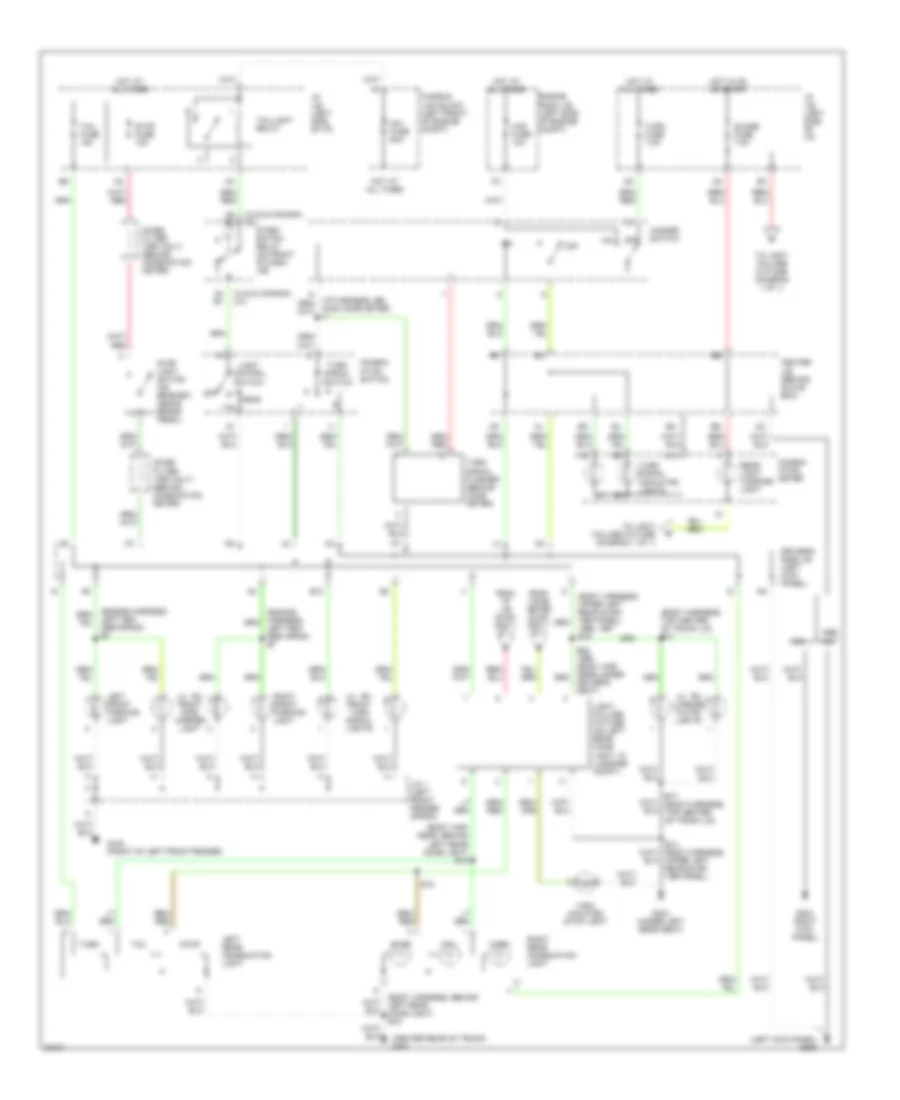
Exterior Lamps Wiring Diagram for Toyota Avalon XLS 1997
List of elements for Exterior Lamps Wiring Diagram for Toyota Avalon XLS 1997:
- (body har- ness, behind left rear comb light) b18
- (body harness, behind left rear comb light) b18
- (body harness, top center of trunk lid) b17
- (body harness, upper left rear quar- ter panel) 1996, 1997 b15
- (center rear of trunk) g407
- (left kick panel) g200
- (xls & canada) (xl)
- 1996,
- A14
- A15
- A4 b1
- A5 b2
- Am1 fuse 80a
- B10
- B14 (body harness, upper left rear quar- ter panel)
- B18
- Center j/b (behind glove box)
- Combin- ation meter
- Combin- ation switch
- Driver's seat)
- Driver's side j/b (left kick panel)
- Engine room j/b (left side of engine compt)
- From comb meter (diag- ram 1 of 1)
- From i/p j/b (diag- ram 1 of 1)
- Fusible link block (left front of engine compt)
- G100 (front of left front fender)
- G203 right kick panel)
- G304 (under left rear seat)
- Guage fuse 7.5a
- Haz fuse 10a
- Hazard switch
- Head
- High mounted stop light
- Hind comb meter) i7
- Hot at all times
- Hot in on or start
- I/p j/b (left side of i/p)
- Integ- ration relay (on front of dash j/b)
- J/c 1 (left front fender apron)
- Left fen- der apron e7
- Left fen- der apron) e7
- Left front parking light
- Left rear combination light
- Lh rh front side marker light
- Lh rh front turn signal lights
- Lh rh license plate lights
- Light control switch
- Light failure fixture (on left rear comb light, in luggage compt)
- Noise filter (1997 0nly) (behind combination meter)
- Off
- Rear light warning light
- Right front parking light
- Right rear combination light
- Stop
- Stop fuse 15a
- Stop light switch (on bracket, above brake pedal)
- Tail
- Tail fuse 15a
- Taillight relay
- To light failure fixture (diagram 1 of 1)
- Turn
- Turn fuse 7.5a
- Turn signal flasher (behind comb meter)
- Turn signal indicator lights
- Turn signal switch