EXTERIOR LIGHTS
Back-up Lamps Wiring Diagram for Toyota Sequoia SR5 2004

List of elements for Back-up Lamps Wiring Diagram for Toyota Sequoia SR5 2004:
- Back-up light relay
- Back-up light switch (park/ neutral position switch)
- Bk (at right "b" pillar)
- E19
- Gauge fuse 15a
- Hot in on or start
- Instrument panel j/b (behind left end of dash)
- Ipo
- J31
- J46
- Junction connector 19 (on left rear of cargo area, behind trim panel)
- Junction connector 20 (on left rear of cargo area, behind trim panel)
- Junction connector 31 & 32 (left kick j32 panel)
- Junction connector 46 & 47 (right kick j47 panel)
- Junction connector 8 (behind left end of dash)
- Left back-up light (rear combination light)
- Right back-up light (rear combination light)
- Sub j/b 3 (behind right side of instrument cluster)
- Sub j/b 4 (behind right side of instrument cluster)
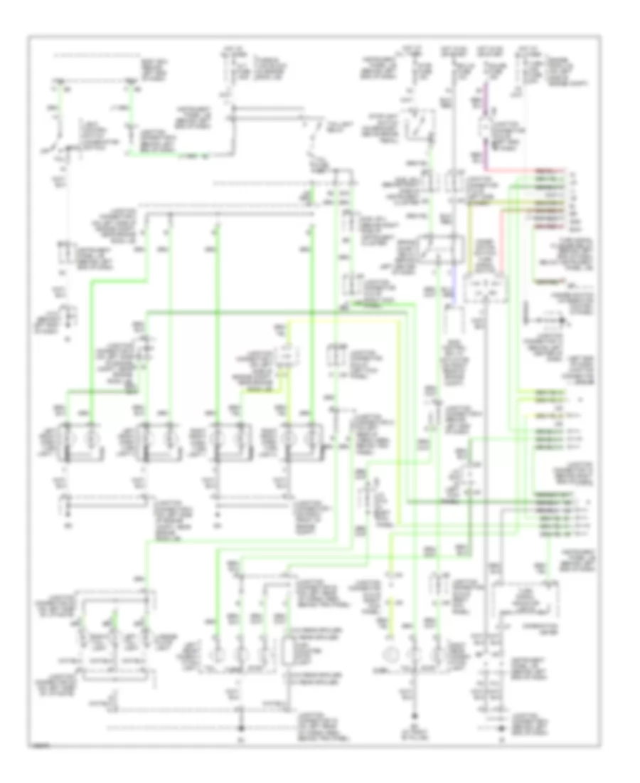
Exterior Lamps Wiring Diagram for Toyota Sequoia SR5 2004
List of elements for Exterior Lamps Wiring Diagram for Toyota Sequoia SR5 2004:
- (combi- nation switch) turn signal switch
- (left end of dash) junction connector 35 & 36
- (w/ rear spoiler)
- (w/o rear spoiler)
- A j48
- Alt fuse 140a
- Bk (at right "b" pillar)
- Body ecu (behind left end of dash)
- Brake inhibit relay (behind left center of dash)
- Combination meter
- E j30
- E11
- E18
- Ecu-ig fuse 10a
- Ehw
- Engine room j/b (on left side of engine compt)
- F10
- Fusible link block (in engine room j/b)
- Gauge fuse 15a
- Gnd
- Hazard switch (integration control & panel)
- Head
- High mounted stop light
- Hot at all times
- Hot in on or start
- Instrument panel j/b (behind left end of dash)
- J/c 29 & (left kick panel)
- J/c 8 (behind left end of dash)
- J29
- J33 j/c 33 & (left kick j34 panel)
- J35
- J36
- J37 a
- J38 a
- J44
- J44 f
- J45 m
- J49 g
- Junction connector 1 (on right front of engine compt)
- Junction connector 12 (behind left center of dash)
- Junction connector 16 (behind right end of dash)
- Junction connector 19 (on left rear of cargo area, behind trim panel)
- Junction connector 2 (on left side of engine compt, near engine room j/b)
- Junction connector 20 (on left rear of cargo area, behind trim panel)
- Junction connector 21 (on left rear of cargo area, behind trim panel)
- Junction connector 22 (on left side of liftgate)
- Junction connector 29 & 30 (left kick panel)
- Junction connector 3 (on left side of engine compt, near engine room j/b)
- Junction connector 35 & 36 (left end of dash) j36
- Junction connector 37 & 38 (left side of dash)
- Junction connector 4 (on left side of engine b compt, near engine room j/b)
- Junction connector 44 & 45 (right kick panel)
- Junction connector 48 & 49 (right kick panel)
- Junction connector 5 (on left side of engine compt, near engine room j/b)
- Junction connector 8 (behind left end of dash)
- Junction connector 9 (behind left end of dash)
- L j29
- Left front park/ turn light 1
- Left front park/ turn light 2
- Left rear combin- ation light
- Left tail- light
- License plate light
- Light control switch (combination switch)
- M j30
- Off
- Park
- Right front park/ turn light 1
- Right front park/ turn light 2
- Right rear combin- ation light
- Right tail- light
- Skid control ecu w/ actuator (on right rear of engine compt)
- Stop
- Stop fuse 15a
- Stoplight switch (on bracket, above brake pedal)
- Sub j/b 4 (behind right side of instrument cluster)
- Tail
- Tail fuse 15a
- Taillight relay
- Trly
- Turn
- Turn signal flasher relay (behind left end of dash, below instrument panel j/b)
- Turn signal indicator lights
- Turn- haz fuse 20a
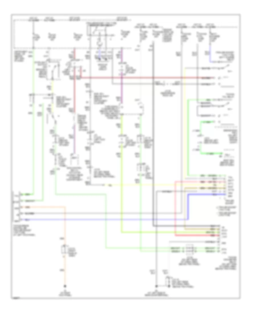
Trailer Tow Wiring Diagram for Toyota Sequoia SR5 2004
List of elements for Trailer Tow Wiring Diagram for Toyota Sequoia SR5 2004:
- (trailer socket 7 pin type) back-up light relay
- (trailer socket 7 pin type) batt charge relay
- 4 pin type
- 7 pin type
- A j32
- B/up
- Back-up lamps circuit
- Batt
- Batt charge fuse 30a
- Bj (at left side of rear quarterpanel)
- Body ecu (behind left end of dash)
- Brake inhibit relay (behind left center of dash)
- Brk
- Bsw
- E18
- E19
- Ecu-ig fuse 10a
- Engine room j/b (on left side of engine compt)
- Engine room r/b 3 (on left side of engine compt)
- Gauge fuse 15a
- Gnd
- Hot at all times
- Hot in on or start
- Ig (at right kick panel)
- Instrument panel j/b (behind left end of dash)
- Ipo
- J/c 16 (behind right end of dash)
- J/c 19 (on left rear of cargo area, behind trim panel)
- J/c 20 (on left rear of cargo area, behind trim panel)
- J/c 28 (near engine room j/b)
- J/c 29 & (left kick panel)
- J/c 31 & 32 (left kick panel)
- J/c 33 & 34 (left kick panel)
- J/c 35 & 36 (left end of dash)
- J/c 37 & (left side of dash)
- J/c 43 (right side of dash)
- J/c 9 (behind left end of dash)
- J29
- J30 e
- J31
- J33
- J35
- J36 d
- J36 e
- J37
- J38
- K12
- Ltin
- Ltot
- Red
- Rtin
- Rtot
- Skid control ecu w/ actuator (on right rear of engine compartment)
- Stin
- Stop
- Stop fuse 15a
- Stoplight switch (on bracket above brake pedal)
- Sttl
- Sttr
- Sub j/b 4 (behind right side of instrument cluster)
- Tail
- Tail fuse 15a
- Towing brake controller (trailer socket 7 pin type) (at left kick panel)
- Towing brk fuse 30a
- Towing converter relay (on left side of cargo area, behind trim panel)
- Towing fuse 30a
- Towing tail fuse 30a
- Towing tail relay
- Trailer socket
- Trly
- Turn signal flasher relay (behind left end of dash, below instrument panel j/b)
- Turn- haz fuse 20a