ANTI-LOCK BRAKES
Anti-lock Brakes Wiring Diagram for Hyundai Accent GS 2007
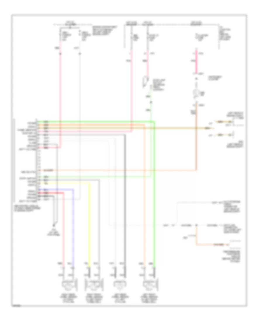
List of elements for Anti-lock Brakes Wiring Diagram for Hyundai Accent GS 2007:
- (left rear of engine compt) pcm
- A/t
- Abs 1 fusible link 40a
- Abs 2 fusible link 40a
- Abs control module (at right rear corner of engine compt)
- Abs fuse 10a
- Abs ind
- Abs ind ctrl
- Batt voltage
- C01-1
- Cluster fuse 10a
- Data link connector (at lower left side of dash)
- Ecm (left rear of engine compt)
- Engine compartment relay & fuse box (on left side of engine compt)
- G12 (at left kick panel)
- Ground
- Hot at all times
- Hot in on or start
- I/p junction box (behind left side of dash)
- I/p-f
- I/p-g
- Instrument cluster
- K-line
- Left front wheel sensor (in left front wheelwell)
- Left rear wheel sensor (at left "c" pillar)
- M/t
- M09-1
- M09-3
- Multipurpose check connector (left rear of engine compt)
- Nca
- On/start in
- Pnk
- Power
- Red
- Right front wheel sensor (in left front wheelwell)
- Right rear wheel sensor (at right "c" pillar)
- Signal
- Stop lamp sw
- Stop lamp switch (on brake pedal support)
- Stop lp fuse 15a
- Tire pressure monitoring module (behind center of dash)
- Usa
- Wheel sens sig
 Čeština
 Dansk
Dansk Deutsch
 Ελληνικά
 English
 English
 Español
 Français
 Français
 עברית
עברית Hrvatski
 Magyar
 Italiano
 日本語
日本語 한국어
한국어 Nederlands
 Polski
 Português
 Português
 Română
 Русский
 Slovenčina
 Slovenščina
 Svenska
 Türkçe
 中文 (中国)
 Suomi
Suomi