CRUISE CONTROL
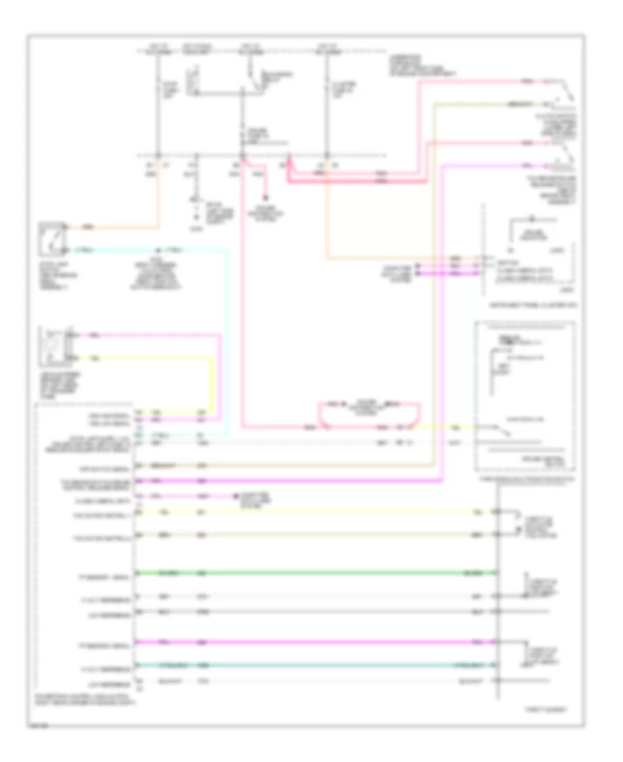
Cruise Control Wiring Diagram for Isuzu i-370 LS 2007
List of elements for Cruise Control Wiring Diagram for Isuzu i-370 LS 2007:
- 5 volt reference
- Class 2 serial data
- Cluster fuse 38 10a
- Clutch switch (if equipped) (lower left side of dash)
- Coast
- Computer data lines system
- Cpp switch signal
- Cruise control switch
- Cruise fuse 19 10a
- Cruise indicator
- E11
- G105
- Hot at all times
- Hot in run or start
- Ignition
- Instrument panel cluster (ipc)
- Logic
- Low reference
- Pnk
- Power distribution system
- Powertrain control module (pcm) (right rear corner of engine compt)
- Resume/ accel
- Run/crank relay
- S100 (body harness, 14.5 cm from accelerator pedal position switch breakout)
- Set/
- Sp105 (left side of engine compt)
- Stop fuse 1 20a
- Stop lamp switch (above brake pedal assembly)
- Tac motor control-1
- Tac motor control-2
- Tcc brake switch/cruise control release signal
- Tcc brake/cruise release switch (above brake pedal assembly)
- Throttle actuator control (tac) motor
- Throttle body
- Throttle position (tp) sens 1
- Throttle position (tp) sens 2
- Tp sensor 1 signal
- Tp sensor 2 signal
- Turn signal/multifunction switch
- Underhood fuse block (on left front side of engine compartment)
- Vehicle speed sensor (vss) (on left rear of transfer case)
- Vss high signal
- Vss low signal
 Čeština
 Dansk
Dansk Deutsch
 Ελληνικά
 English
 English
 Español
 Français
 Français
 עברית
עברית Hrvatski
 Magyar
 Italiano
 日本語
日本語 한국어
한국어 Nederlands
 Polski
 Português
 Português
 Română
 Русский
 Slovenčina
 Slovenščina
 Svenska
 Türkçe
 中文 (中国)
 Suomi
Suomi