ENGINE PERFORMANCE
3.0L
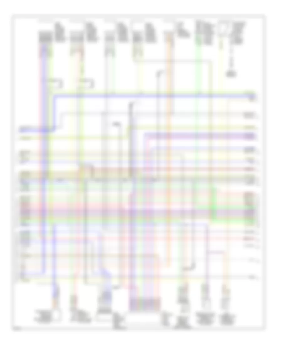
3.0L, Engine Performance Wiring Diagrams (1 of 3) for Infiniti J30 t 1997


List of elements for 3.0L, Engine Performance Wiring Diagrams (1 of 3) for Infiniti J30 t 1997:
- (rear of engine)
- (right front of engine compt)
- (right front of trunk)
- 08/27/96
- 56a
- 57a
- A/c system
- Acc
- Box)
- Cooling fan system
- Dropping resistor (right rear of trunk)
- Eccs relay (in relay & fuse
- Engine control module (right kick panel)
- Fuel pump (in fuel tank)
- Fuel pump control module (right rear of trunk)
- Fuel pump relay (above left kick panel)
- Fuse 15a
- Fuse 7.5a
- Fuse and fusible link box
- Fuse block (in j/b)
- Fuse block (j/b)
- G100
- G115
- G401
- Hot at all
- Hot at all times
- Hot in start
- Iacv-aac valve
- Iacv-air regulator
- Iacv-ficd solenoid valve
- Ignition switch
- Instrument cluster system
- Intake air temperature sensor (left front corner of eng compt)
- J/c 13 (right front of trunk)
- Knock sensor (center rear of engine)
- Nca
- Off
- Or on
- Pnk
- Power steering oil pressure switch (on power steering high pressure line)
- Power transistor unit (top right front of engine)
- Start
- Times
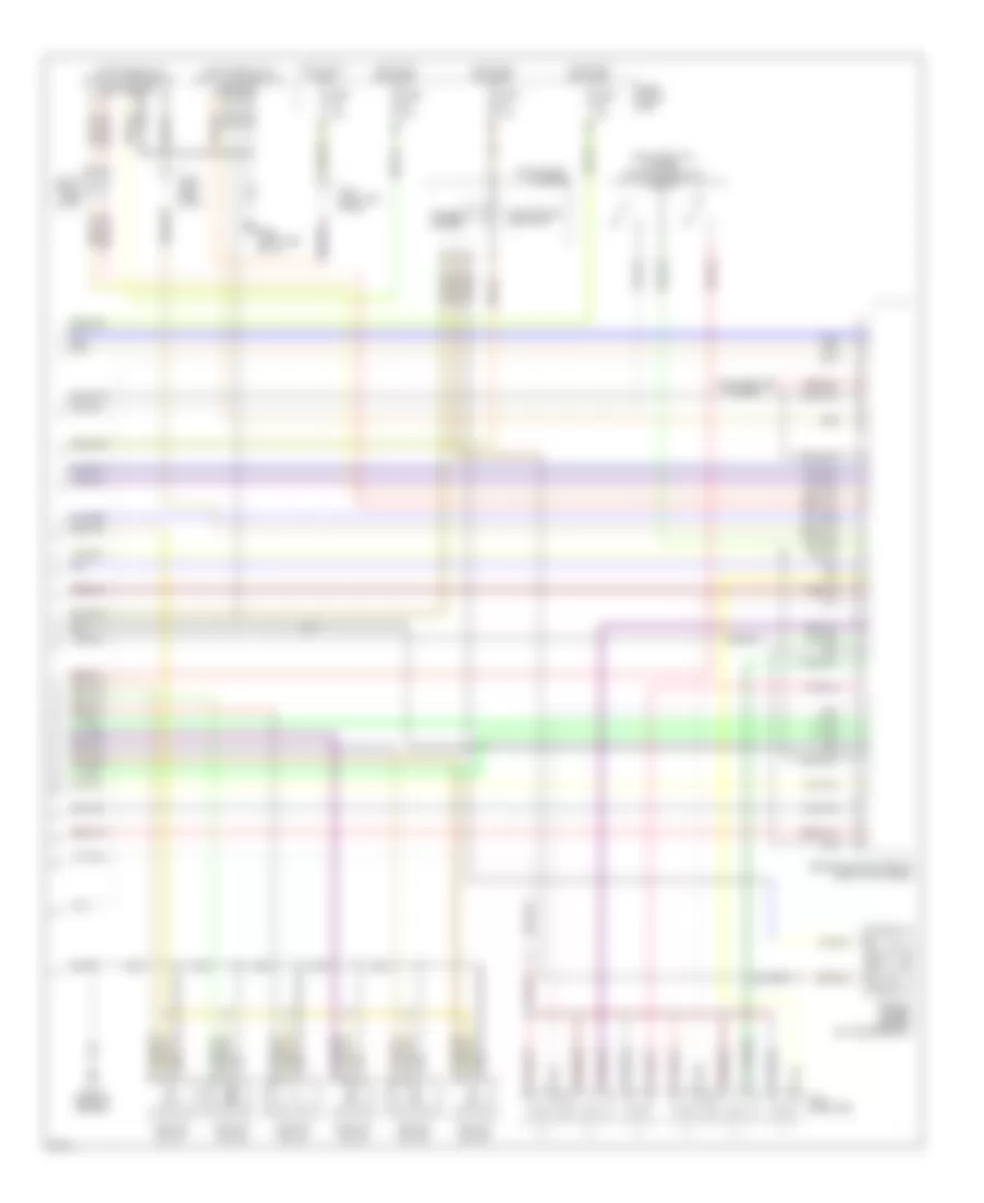
3.0L, Engine Performance Wiring Diagrams (2 of 3) for Infiniti J30 t 1997
List of elements for 3.0L, Engine Performance Wiring Diagrams (2 of 3) for Infiniti J30 t 1997:
- A/t control unit (left kick panel)
- Cam- shaft position sensor (left front of engine)
- Canister control vacuum check switch (left side of engine compt)
- Crankshaft position sensor (center rear of engine)
- Egr temperature sensor (top center of engine)
- Egrc solenoid valve (left front of engine)
- Engine coolant temperature sensor (front center of engine)
- Evap canister purge control solenoid valve (on left strut tower)
- G115 (rear of engine)
- Left front heated oxygen sensor (on left exhaust manifold)
- Left rear heated oxygen sensor (below center of vehicle)
- Mass air flow sensor (left side of engine)
- Nca
- Right front heated oxygen sensor (on right exhaust manifold)
- Right rear heated oxygen sensor (below center of vehicle)
- Throttle position sensor (on side of throttle body)
3.0L, Engine Performance Wiring Diagrams (3 of 3) for Infiniti J30 t 1997
List of elements for 3.0L, Engine Performance Wiring Diagrams (3 of 3) for Infiniti J30 t 1997:
- (left front of engine) throttle position switch
- (left side of i/p) data link connector (for consult)
- (left side of i/p) data link connector (for gst)
- 25a
- 64a
- Cluster
- Defogger system
- Engine control module (right kick panel)
- Fuel injectors
- Fuse 15a
- Fuse 7.5a
- Fuse block (j/b)
- G115 (rear of engine)
- G202 (left side of i/p)
- Hot at all times
- Hot in on or start
- Ignition coil #1
- Ignition coil #2
- Ignition coil #3
- Ignition coil #4
- Ignition coil #5
- Ignition coil #6
- Instrument
- J/c 11 (right side of i/p)
- J/c 7 (left kick panel)
- J/c 9 (left side of i/p)
- Malfunction indicator
- Speedo- meter
- Vehicle speed sensor (on transmission)

 Čeština
 Dansk
Dansk Deutsch
 Ελληνικά
 English
 English
 Español
 Français
 Français
 עברית
עברית Hrvatski
 Magyar
 Italiano
 日本語
日本語 한국어
한국어 Nederlands
 Polski
 Português
 Português
 Română
 Русский
 Slovenčina
 Slovenščina
 Svenska
 Türkçe
 中文 (中国)