SHIFT INTERLOCK
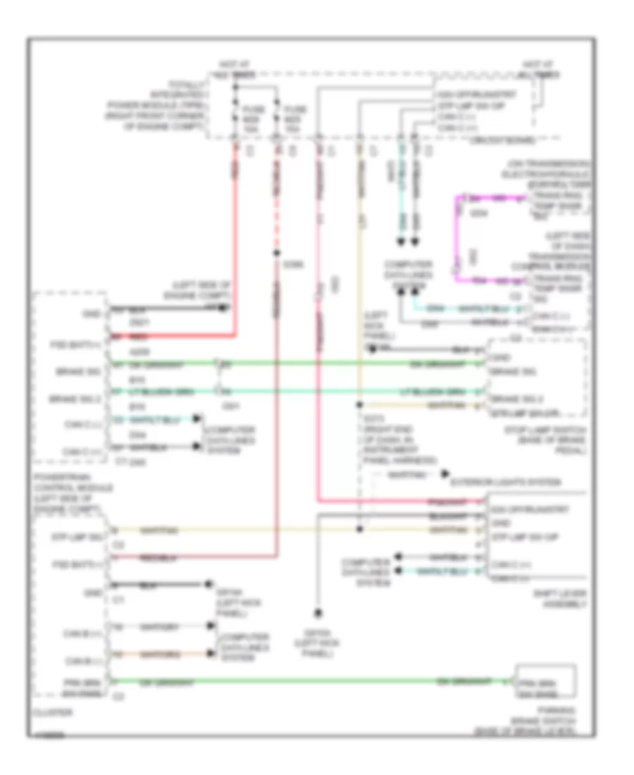
Shift Interlock Wiring Diagram for Jeep Wrangler Sport 2014
List of elements for Shift Interlock Wiring Diagram for Jeep Wrangler Sport 2014:
- (left kick panel) g914a
- (left side of dash) transmission control module
- (left side of engine compt) g921a
- (on transmission) electrohydraulic control unit
- A209
- B15
- B16
- Brake sig
- Brake sig 2
- Can b (+)
- Can b (-)
- Can c (+)
- Can c (-)
- Circuit board
- Cluster
- Computer data lines system
- D64
- D65
- Exterior lights system
- Fsd batt(+)
- Fuse m20 15a
- Fuse m28 10a
- G910a (left kick panel)
- G914a (left kick panel)
- Gnd
- Hot at all times
- I204
- I301
- I302
- Ign off/run/strt
- L51
- Parking brake switch (base of brake lever)
- Powertrain control module (left side of engine compt)
- Prk brk sw snse
- Red
- S373 (right end of dash, in instrument panel harness)
- S396
- Shift lever assembly
- Stop lamp switch (base of brake pedal)
- Stp lmp sig
- Stp lmp sw o/p
- Stp lmp sw o/p can c (-)
- T54
- Totally integrated power module (tipm) (right front corner of engine compt)
- Trans rng temp snsr sig
- Z921
 Čeština
 Dansk
Dansk Deutsch
 Ελληνικά
 English
 English
 Español
 Français
 Français
 עברית
עברית Hrvatski
 Magyar
 Italiano
 日本語
日本語 한국어
한국어 Nederlands
 Polski
 Português
 Português
 Română
 Русский
 Slovenčina
 Slovenščina
 Svenska
 Türkçe
 中文 (中国)
 Suomi
Suomi