SHIFT INTERLOCK
Shift Interlock Wiring Diagram for Lexus IS F 2008
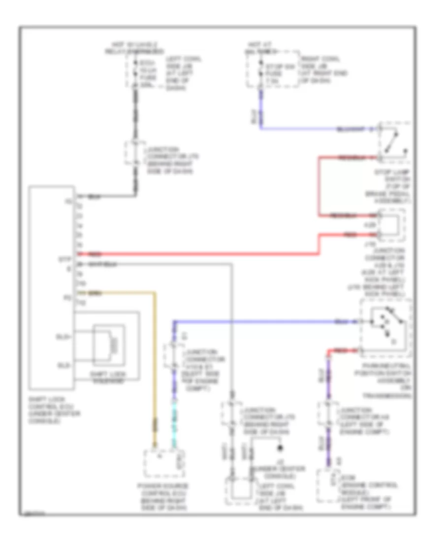
List of elements for Shift Interlock Wiring Diagram for Lexus IS F 2008:
- A29
- D29
- Ecm (engine control module) (left front of engine compt)
- Ecu- ig lh fuse 10a
- Hot at all times
- Hot w/ lh-ig 2 relay energized
- J10
- J2 (under center console)
- Junction connector a10 & e1 (left side a10
- Junction connector a29 & j10 (a29: at left kick panel) (j10: behind left kick panel)
- Junction connector a8 (left side of engine compt)
- Junction connector j70 (behind right side of dash)
- Left cowl side j/b (at left end of dash)
- Of engine compt)
- Park/neutral position switch assembly (on
- Power source control ecu (behind right side of dash)
- Red
- Right cowl side j/b (at right end of dash)
- Shift lock control ecu (under center console)
- Shift lock solenoid
- Sls+
- Sls-
- Sta
- Stop lamp switch (top of brake pedal assembly)
- Stop sw fuse 7.5a
- Stp
- Str1
- Transmission)
 Čeština
 Dansk
Dansk Deutsch
 Ελληνικά
 English
 English
 Español
 Français
 Français
 עברית
עברית Hrvatski
 Magyar
 Italiano
 日本語
日本語 한국어
한국어 Nederlands
 Polski
 Português
 Português
 Română
 Русский
 Slovenčina
 Slovenščina
 Svenska
 Türkçe
 中文 (中国)
 Suomi
Suomi