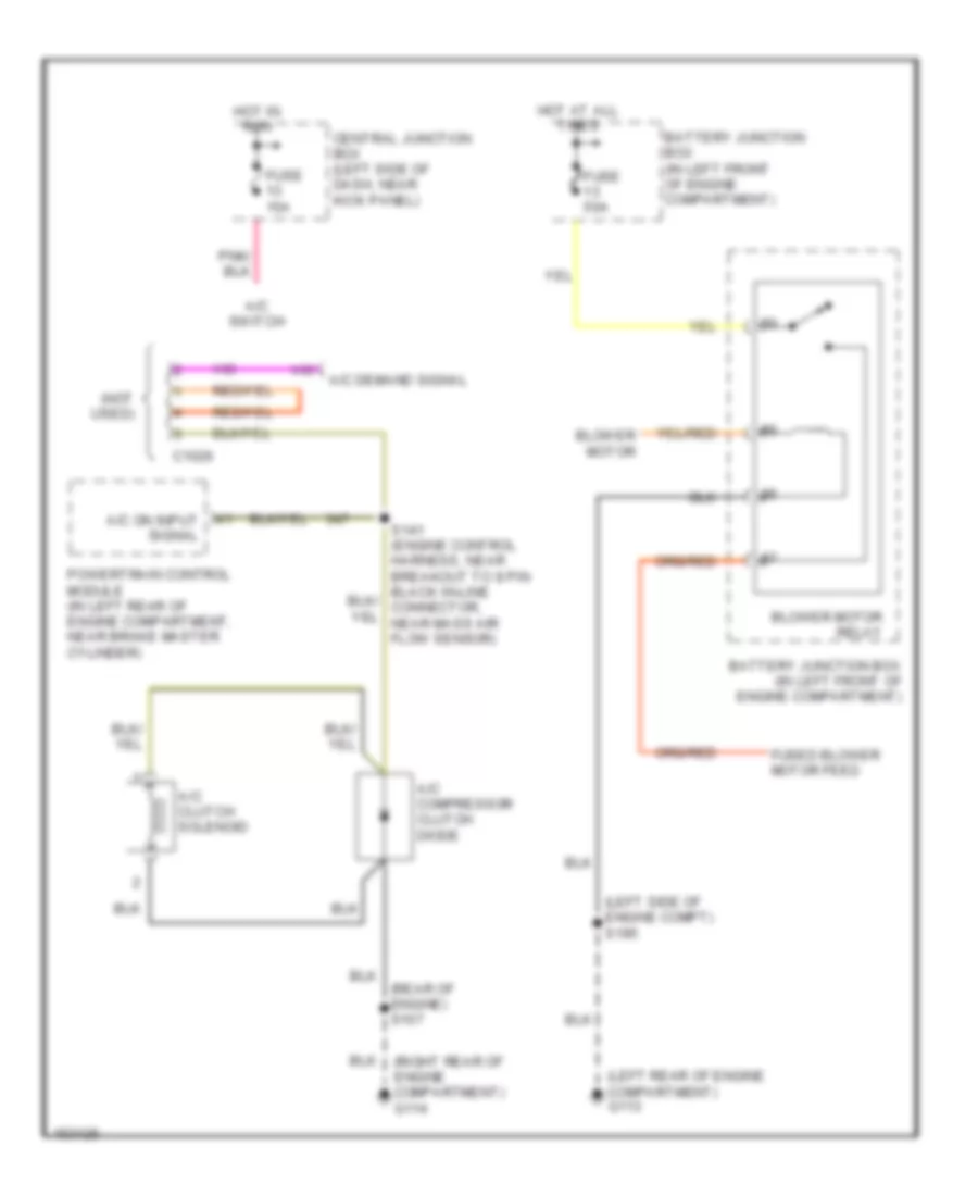
AIR CONDITIONING
4.2L
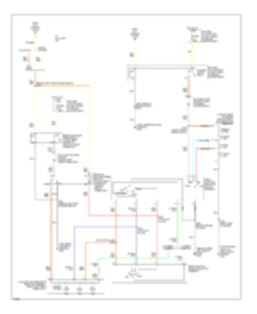
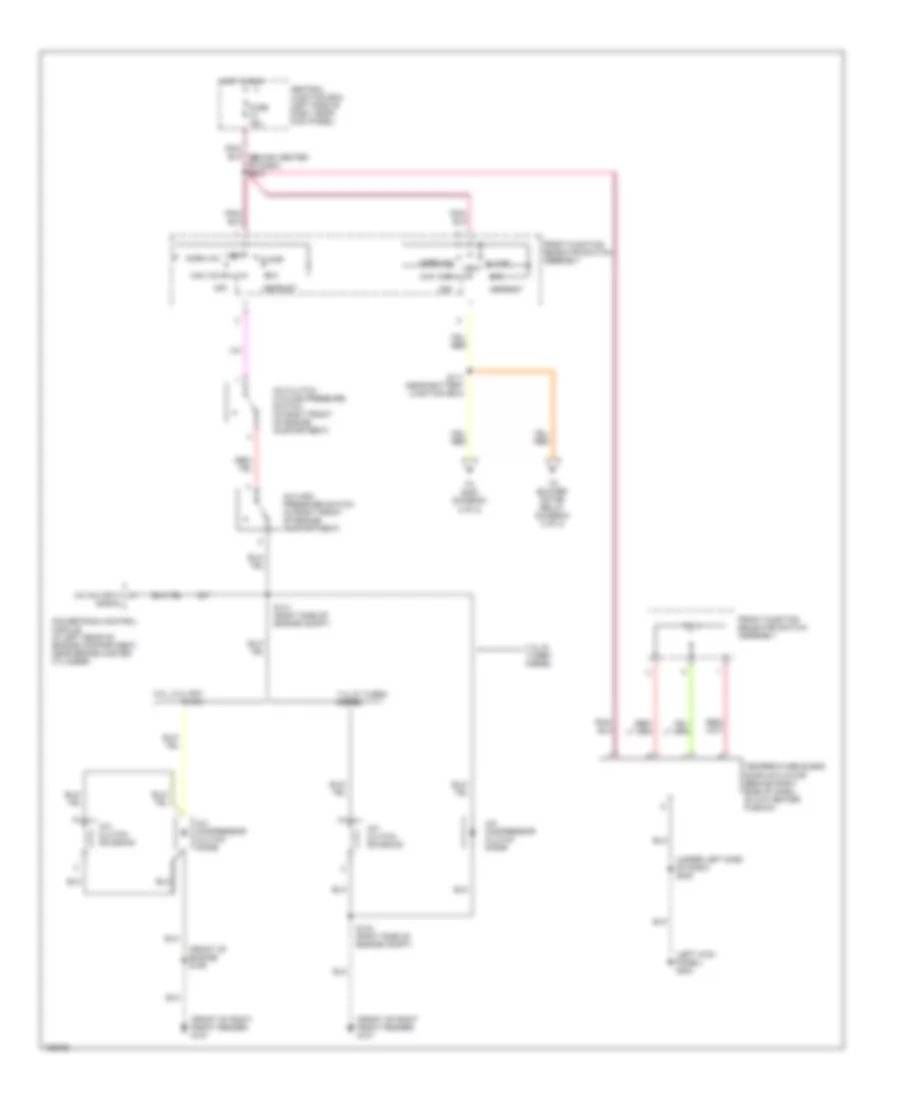
4.2L, Manual A/C Wiring Diagram, with Stripped Chassis for Ford Econoline E350 Super Duty 2002


List of elements for 4.2L, Manual A/C Wiring Diagram, with Stripped Chassis for Ford Econoline E350 Super Duty 2002:
- (engine control harness, near breakout to battery junction box) s110
- (left rear of engine compartment) g113
- (left rear of engine compt)
- (left side of engine compt) s195
- (not used)
- (rear of engine) s107
- (right rear of engine compartment) g114
- 87a
- A/c clutch relay
- A/c clutch solenoid
- A/c compressor clutch diode
- A/c demand signal
- A/c on input signal
- A/c relay control
- A/c switch
- Battery junction box (in left front of engine compartment)
- Blower motor
- Blower motor relay
- C1026
- Central junction box (left side of dash, near kick panel)
- Fuse 10a
- Fuse 15a
- Fuse 30a
- Fuse 50a
- Fused blower motor feed
- Hot at all times
- Hot in run
- Note: pcm power relay energized w/ignition switch in run or start position
- Pcm power relay
- Powertrain control module (in left rear of engine compartment, near brake master cylinder)
- Red
- S142
4.2L, Manual A/C Wiring Diagram, without Stripped Chassis (1 of 2) for Ford Econoline E350 Super Duty 2002
List of elements for 4.2L, Manual A/C Wiring Diagram, without Stripped Chassis (1 of 2) for Ford Econoline E350 Super Duty 2002:
- (front of right front fender) g101
- (left kick panel) g204
- (left rear of engine compt) s142
- (near battery junction box) s110
- (near battery junction box) s111
- (rear of engine) s107
- (under left side of dash) s223
- 87a
- A/c clutch cycling pressure switch (in right front of engine compartment)
- A/c clutch relay
- A/c clutch solenoid
- A/c compressor clutch diode
- A/c high pressure switch) (in right front of engine compartment)
- A/c on input signal
- A/c relay control
- Battery junction box (in left front of engine compartment)
- Blend door actuator (behind right side of dash, on a/c heater plenum)
- Central junction box (left side of dash, near kick panel)
- Defrost
- Floor
- Front function selector switch assembly
- Fuse 10a
- Fuse 15a
- Fuse 30a
- Hot at all times
- Hot in run
- Max a/c
- Mix
- Norm a/c
- Note: pcm power relay energized w/ignition switch in run or start position
- Off
- Pcm power relay
- Powertrain control module (in left rear of engine compartment, near brake master cylinder)
- Red
- To blower motor relay (diagram 2 of 2)
- To s400 (diagram 2 of 2)
- Vent
- Vent norm a/c
4.2L, Manual A/C Wiring Diagram, without Stripped Chassis (2 of 2) for Ford Econoline E350 Super Duty 2002
List of elements for 4.2L, Manual A/C Wiring Diagram, without Stripped Chassis (2 of 2) for Ford Econoline E350 Super Duty 2002:
- (behind left side of rear seats) s400
- (behind upper left side of dash) g203
- (front of right front fender) g101
- (in right rear of engine compartment) blower motor resistor
- (left rear corner of vehicle) g400
- (left rear of engine compt) s122
- (left upper radiator support) g100
- (not used)
- (top of "b" pillar) s303
- .25 ohms +/- 10%
- .8 ohms +/- 10%
- 2.7 ohms +/- 10%
- 87a
- Auxiliary blower motor (above left rear wheelwell)
- Auxiliary blower motor resistor assembly (above left rear wheelwell)
- Battery junction box (in left front of engine compartment)
- Blower motor (on right side of engine compartment)
- Blower motor relay
- Compartment)
- Cutaways
- From s111 (diagram 1 of 2)
- Front function selector switch assembly
- Fuse 50a
- High
- Hot at all times
- Low
- Low/rear
- Off
- Rear a/c blower speed relay 1 (in left rear corner of vehicle, above wheelwell)
- Rear a/c blower speed relay 2 (in left rear corner of vehicle, above wheelwell)
- Rear function selector switch assembly
- S143 (right side of engine
- S144 (right side of engine compt)
- S202 behind center of dash)
- S304 (top of "b" pillar)
- S305 (top of "b" pillar)
- S401 (behind left side of rear seats)
- Thermal limiter
- Vans & wagons
- W/ auxiliary a/c
- W/ rear control
- W/o rear control
4.6L
4.6L, Manual A/C Wiring Diagram, with Stripped Chassis for Ford Econoline E350 Super Duty 2002
List of elements for 4.6L, Manual A/C Wiring Diagram, with Stripped Chassis for Ford Econoline E350 Super Duty 2002:
- (left rear of engine compartment) g113
- (left side of engine compt) s195
- (not used)
- (rear of engine) s107
- (right rear of engine compartment) g114
- A/c clutch solenoid
- A/c compressor clutch diode
- A/c demand signal
- A/c on input signal
- A/c switch
- Battery junction box (in left front of engine compartment)
- Blower motor
- Blower motor relay
- C1026
- Central junction box (left side of dash, near kick panel)
- Fuse 15a
- Fuse 50a
- Fused blower motor feed
- Hot at all times
- Hot in run
- Powertrain control module (in left rear of engine compartment, near brake master cylinder)
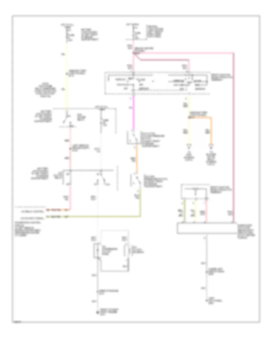
4.6L, Manual A/C Wiring Diagram, without Stripped Chassis (1 of 2) for Ford Econoline E350 Super Duty 2002
List of elements for 4.6L, Manual A/C Wiring Diagram, without Stripped Chassis (1 of 2) for Ford Econoline E350 Super Duty 2002:
- (front of right front fender) g101
- (left kick panel) g204
- (left rear of engine compt) s142
- (near battery junction box) s110
- (near battery junction box) s111
- (rear of engine) s107
- (under left side of dash) s223
- 87a
- A/c clutch cycling pressure switch (in right front of engine compartment)
- A/c clutch relay
- A/c clutch solenoid
- A/c compressor clutch diode
- A/c high pressure switch (in right front of engine compartment)
- A/c on input signal
- A/c relay control
- Battery junction box (in left front of engine compartment)
- Blend door actuator (behind right side of dash, on a/c heater plenum)
- Central junction box (left side of dash, near kick panel)
- Defrost
- Floor
- Front function selector switch assembly
- Fuse 15a
- Fuse 30a
- Hot at all times
- Hot in run
- Max a/c
- Mix
- Norm a/c
- Note: pcm power relay energized w/ignition switch in run or start position
- Off
- Pcm power relay
- Powertrain control module (in left rear of engine compartment, near brake master cylinder)
- Red
- S166 (right side of engine compartment)
- To blower motor relay (diagram 2 of 2)
- To s400 (diagram 2 of 2)
- Vent
- Vent norm a/c
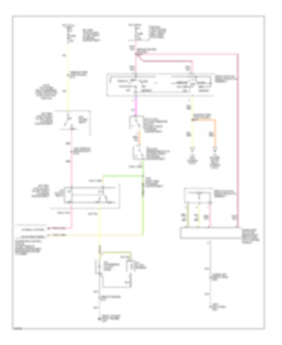
4.6L, Manual A/C Wiring Diagram, without Stripped Chassis (2 of 2) for Ford Econoline E350 Super Duty 2002
List of elements for 4.6L, Manual A/C Wiring Diagram, without Stripped Chassis (2 of 2) for Ford Econoline E350 Super Duty 2002:
- (behind left side of rear seats) s400
- (behind upper left side of dash) g203
- (front of right front fender) g101
- (in right rear of engine compartment) blower motor resistor
- (left rear corner of vehicle) g400
- (left rear of engine compt) s122
- (left upper radiator support) g100
- (not used)
- (top of "b" pillar) s303
- .25 ohms +/- 10%
- .8 ohms +/- 10%
- 2.7 ohms +/- 10%
- 87a
- Auxiliary blower motor (above left rear wheelwell)
- Auxiliary blower motor resistor assembly (above left rear wheelwell)
- Battery junction box (in left front of engine compartment)
- Blower motor (on right side of engine compartment)
- Blower motor relay
- Compartment)
- Cutaways
- From s111 (diagram 1 of 2)
- Front function selector switch assembly
- Fuse 50a
- High
- Hot at all times
- Low
- Low/rear
- Off
- Rear a/c blower speed relay 1 (in left rear corner of vehicle, above wheelwell)
- Rear a/c blower speed relay 2 (in left rear corner of vehicle, above wheelwell)
- Rear function selector switch assembly
- S143 (right side of engine
- S144 (right side of engine compt)
- S202 behind center of dash)
- S304 (top of "b" pillar)
- S305 (top of "b" pillar)
- S401 (behind left side of rear seats)
- Thermal limiter
- Vans & wagons
- W/ auxiliary a/c
- W/ rear control
- W/o rear control
5.4L
5.4L, Manual A/C Wiring Diagram, with Stripped Chassis for Ford Econoline E350 Super Duty 2002
List of elements for 5.4L, Manual A/C Wiring Diagram, with Stripped Chassis for Ford Econoline E350 Super Duty 2002:
- (left rear of engine compartment) g113
- (left side of engine compt) s195
- (not used)
- (rear of engine) s107
- (right rear of engine compartment) g114
- A/c clutch solenoid
- A/c compressor clutch diode
- A/c demand signal
- A/c on input signal
- A/c switch
- Battery junction box (in left front of engine compartment)
- Blower motor
- Blower motor relay
- C1026
- Central junction box (left side of dash, near kick panel)
- Fuse 15a
- Fuse 50a
- Fused blower motor feed
- Hot at all times
- Hot in run
- Powertrain control module (in left rear of engine compartment, near brake master cylinder)
5.4L, Manual A/C Wiring Diagram, without Stripped Chassis (1 of 2) for Ford Econoline E350 Super Duty 2002
List of elements for 5.4L, Manual A/C Wiring Diagram, without Stripped Chassis (1 of 2) for Ford Econoline E350 Super Duty 2002:
- (front of engine) s189
- (front of right front fender) g101
- (left kick panel) g204
- (under left side of dash) s223
- 5.4l, 5.4l ngv & 6.8l
- 7.3l di turbo diesel
- A/c clutch cycling pressure switch (in right front of engine compartment)
- A/c clutch solenoid
- A/c compressor clutch diode
- A/c high pressure switch (in right front of engine compartment)
- A/c on input signal
- Central junction box (left side of dash, near kick panel)
- Defrost
- Floor
- Front function selector switch assembly
- Fuse 15a
- Hot in run
- Max a/c
- Mix
- Norm a/c
- Off
- Powertrain control module (in left rear of engine compartment, near brake master cylinder)
- S111 (near battery junction box)
- S141 (right side of engine compt)
- S143 (right side of engine compt)
- Temperature blend door actuator (behind right side of dash, on a/c heater plenum)
- To blower motor relay (diagram 2 of 2)
- To s400 (diagram 2 of 2)
- Vent
- Vent norm a/c
5.4L, Manual A/C Wiring Diagram, without Stripped Chassis (2 of 2) for Ford Econoline E350 Super Duty 2002
List of elements for 5.4L, Manual A/C Wiring Diagram, without Stripped Chassis (2 of 2) for Ford Econoline E350 Super Duty 2002:
- (behind left side of rear seats) s400
- (behind upper left side of dash) g203
- (front of right front fender) g101
- (in right rear of engine compartment) blower motor resistor
- (left rear corner of vehicle) g400
- (left rear of engine compt) s122
- (left upper radiator support) g100
- (not used)
- (top of "b" pillar) s303
- .25 ohms +/- 10%
- .8 ohms +/- 10%
- 2.7 ohms +/- 10%
- 87a
- Auxiliary blower motor (above left rear wheelwell)
- Auxiliary blower motor resistor assembly (above left rear wheelwell)
- Battery junction box (in left front of engine compartment)
- Blower motor (on right side of engine compartment)
- Blower motor relay
- Compartment)
- Cutaways
- From s111 (diagram 1 of 2)
- Front function selector switch assembly
- Fuse 50a
- High
- Hot at all times
- Low
- Low/rear
- Off
- Rear a/c blower speed relay 1 (in left rear corner of vehicle, above wheelwell)
- Rear a/c blower speed relay 2 (in left rear corner of vehicle, above wheelwell)
- Rear function selector switch assembly
- S143 (right side of engine
- S144 (right side of engine compt)
- S202 behind center of dash)
- S304 (top of "b" pillar)
- S305 (top of "b" pillar)
- S401 (behind left side of rear seats)
- Thermal limiter
- Vans & wagons
- W/ auxiliary a/c
- W/ rear control
- W/o rear control

 Čeština
 Dansk
Dansk Deutsch
 Ελληνικά
 English
 English
 Español
 Français
 Français
 עברית
עברית Hrvatski
 Magyar
 Italiano
 日本語
日本語 한국어
한국어 Nederlands
 Polski
 Português
 Português
 Română
 Русский
 Slovenčina
 Slovenščina
 Svenska
 Türkçe
 中文 (中国)