СИСТЕМА КОНДИЦИОНЕРА
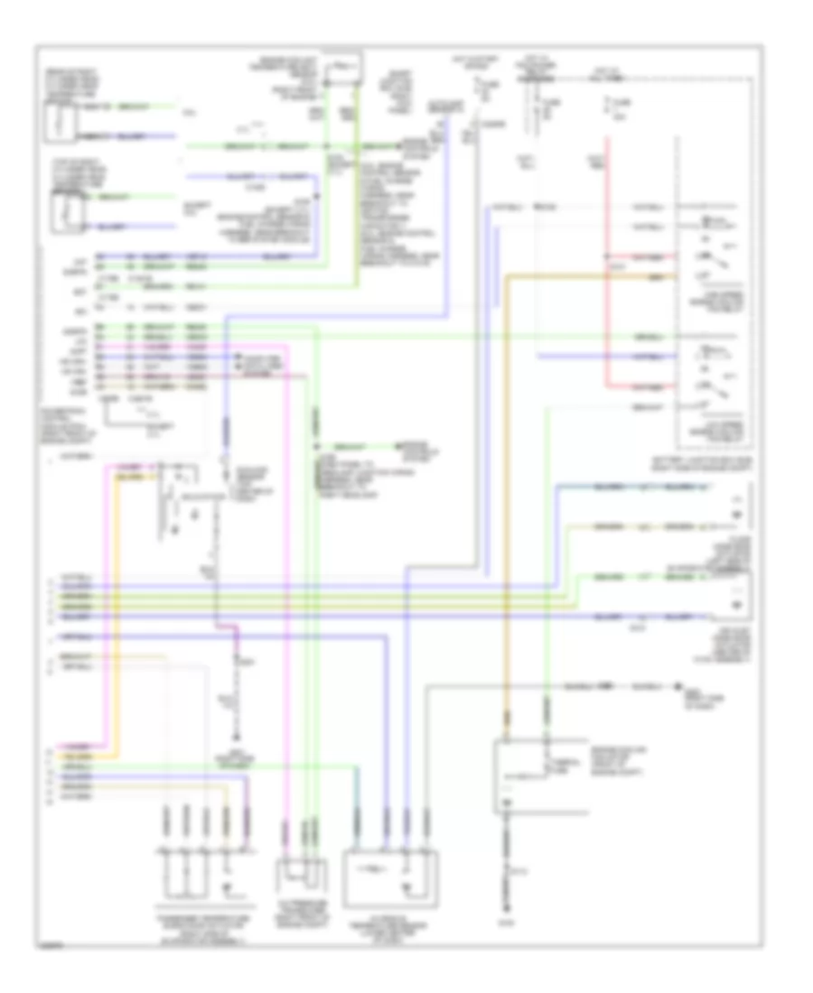
Электросхема кондиционера (1 из 2) для Ford Mustang 2013


Электросхема кондиционера (1 из 2) для Ford Mustang 2013 - Список элементов:
- (blower motor assembly) blower motor speed control
- (front of a/c compressor)
- (main wiring harness, in breakout to front display interface module)
- (near breakout to driver temperature blend door actuator)
- (near breakout to floor mode door actuator)
- (right kick panel)
- (right side of dash) g200
- (right side of engine compt)
- A/c clutch relay
- A/c compressor clutch field coil
- Ambient air temperature sensor (center front of engine compt)
- Battery junction box (bjb)
- Blower motor (under hvac unit)
- Blower motor relay
- Blower relay
- C110
- C211
- C212
- C2280a
- C2280e
- C294a
- C294b
- Ch122
- Ch123
- Ch202
- Ch203
- Ch207
- Ch208
- Ch212
- Ch213
- Ch228
- Ch229
- Ch238
- Ch239
- Chs29
- Chs30
- Computer data lines system
- Defogger system
- Defrost request
- Driv htd seat req
- Driv temp act fdbk
- Driv temp door ccw
- Driv temp door cw
- Driver sunload
- Driver temperature blend door actuator (left side of evaporator assembly)
- Evap temp sensor
- Evaporator discharge air temperature sensor (right side of evaporator assembly)
- Fuse 10a
- Fuse 30a
- Fuse 5a
- G100
- G201 (right side of dash)
- Gd116
- Gnd
- Hot at all times
- Hot in run or acc
- Hvac module
- In car temp sensor
- Lh111
- Mode 1 act fdbk
- Mode door 1 ccw
- Mode door 1 cw
- Mode door 2 ccw
- Mode door 2 cw
- Ms can+
- Ms can-
- Mtr
- Oat
- Panel/defrost mode door actuator (right side of dash)
- Pass htd seat req
- Pass temp act fdbk
- Pass temp door ccw
- Pass temp door cw
- Passenger sunload
- Pwm
- Recirc ccw
- Recirc cw
- Red
- Return
- Rh111
- S112
- S130
- S201
- S202
- S203 (main wiring harness, near breakout to panel/defrost mode door actuator)
- S218
- Sbp15
- Seats system
- Smart junction box (sjb)
- Variable blwr ctrl
- Vbatt
- Vdb06
- Vdb07
- Vh101
- Vh406
- Vh407
- Vh414
- Vh416
- Vh417
- Vh436
- Vh440
- Vh441
- Vref
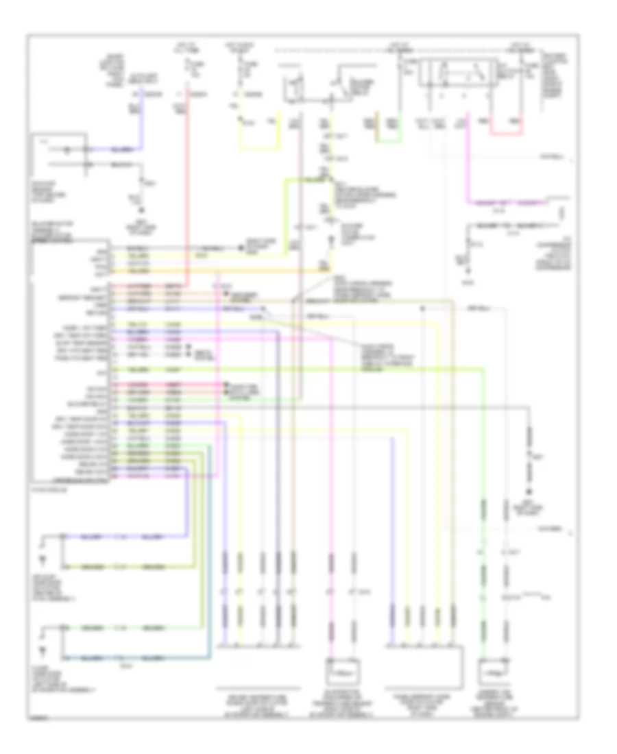
Электросхема кондиционера (2 из 2) для Ford Mustang 2013
Электросхема кондиционера (2 из 2) для Ford Mustang 2013 - Список элементов:
- (5.8l: engine control sensor & fuel charge wiring harness, near breakout to ignition transformer capacitor 1) (5.0l: engine control sensor & fuel charge wiring harness, near breakout to c1019)
- (rear of right cylinder head) cylinder head temperature sensor
- (right kick panel)
- (top of right cylinder head) cylinder head temperature sensor
- 3.7l
- 5.8l
- A/c pressure transducer (right front of engine compt)
- Accr
- Acpt
- Air inlet mode door actuator (center of hvac assembly)
- Autolamp sensor in
- Battery junction box (bjb) (right side of engine compt)
- C1026
- C1381b
- C1381e
- C175b
- C175e
- C212
- C2280b
- Cec01
- Cec02
- Ch302
- Cht
- Computer data lines system
- Ect
- Engine controls system
- Engine coolant temperature (ect) sensor (5.8l) (right front of engine)
- Engine cooling fan motor (front of engine compt)
- Except 3.7l
- Except 5.8l
- Floor mode door actuator (left side of evaporator assembly)
- Fuse 40a
- Fuse 5a
- G100
- G200 (right side of dash)
- G201 (right side of dash)
- Hfc
- High speed engine cooling fan relay
- Hot at all times
- Hot in start or run
- Hot w/ pcm power relay energized
- Hs can+
- Hs can-
- In-vehicle temperature sensor (lower center of dash)
- Le423
- Lfc
- Low speed engine cooling fan relay
- Nca
- Passenger temperature blend door actuator (right side of evaporator assembly)
- Powertrain control module (pcm) (right front of engine compt)
- Re141
- Re405
- S102 (except 3.7l)
- S106 (except 3.7l) (engine control sensor & fuel charge wiring harness, near breakout to egr system module)
- S112
- S121
- S125
- S200
- S201
- Sigrtn
- Smart junction box (sjb)
- Solid state
- Sunload sensor (top center of dash)
- Thermal fuse
- Vdb04
- Vdb05
- Ve712
- Vh433
- Vref
Электросхема кондиционера с ручный управлением (1 из 2) для Ford Mustang 2013
Электросхема кондиционера с ручный управлением (1 из 2) для Ford Mustang 2013 - Список элементов:
- (blower motor assembly) blower motor speed control
- (front of a/c compressor)
- (main wiring harness, in breakout to front display interface module)
- (right kick panel)
- (right side of dash) g200
- (right side of engine compt)
- 5.8l
- A/c clutch relay
- A/c compressor clutch field coil
- Air inlet mode door actuator (center of hvac assembly)
- Ambient air temperature sensor (center front of engine compt)
- Autolamp sens input
- Battery junction box (bjb)
- Blower motor (under hvac unit)
- Blower motor relay
- Blower relay
- C110
- C133
- C211
- C212
- C2280a
- C2280b
- C2280e
- Ch122
- Ch123
- Ch202
- Ch203
- Ch207
- Ch208
- Ch228
- Ch229
- Ch238
- Ch239
- Chs29
- Chs30
- Computer data lines system
- Defogger system
- Defrost request
- Driv htd seat req
- Driv temp act fdbk
- Driv temp door ccw
- Driv temp door cw
- Driver temperature blend door actuator (left side of evaporator assembly)
- Evap temp sensor
- Evaporator discharge air temperature sensor (right side of evaporator assembly)
- Floor mode door actuator (left side of evaporator assembly)
- Fuse 10a
- Fuse 30a
- Fuse 5a
- G100
- G201 (right side of dash)
- Gd116
- Gnd
- Hot at all times
- Hot in run or acc
- Hvac module
- Lh111
- Mode 1 act fdbk
- Mode door 1 ccw
- Mode door 1 cw
- Mode door 2 ccw
- Mode door 2 cw
- Mot-
- Ms can+
- Ms can-
- Oat
- Panel/defrost mode door actuator (right side of dash)
- Pass htd seat req
- Pwm
- Recirc ccw
- Recirc cw
- Red
- Return
- Rh111
- S112
- S130
- S201
- S202
- S203 (main wiring harness, near breakout to panel/defrost mode door actuator)
- S211 (heater blower motor wiring harness, near breakout to c212)
- Sbp15
- Seats system
- Smart junction box (sjb)
- Sunload sensor (top center of dash)
- Variable blwr ctrl
- Vbatt
- Vdb06
- Vdb07
- Vh101
- Vh406
- Vh407
- Vh436
- Vh440
- Vref
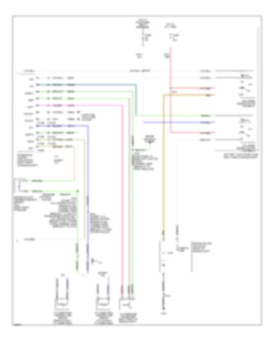
Электросхема кондиционера с ручный управлением (2 из 2) для Ford Mustang 2013
Электросхема кондиционера с ручный управлением (2 из 2) для Ford Mustang 2013 - Список элементов:
- 3.7l
- 5.8l
- A/c pressure transducer (right front of engine compt)
- Accr
- Acpt
- Battery junction box (bjb) (right side of engine compt)
- C1026
- C1381b
- C1381e
- C175b
- C175e
- Cec01
- Cec02
- Ch302
- Cht
- Computer data lines system
- Cylinder head temperature sensor (rear of right cylinder head)
- Cylinder head temperature sensor (top of right cylinder head)
- Ect
- Engine controls system
- Engine coolant temperature (ect) sensor (5.8l) (right front of engine)
- Engine cooling fan motor (front of engine compt)
- Except 3.7l
- Except 5.8l
- Fuse 40a
- Fuse 5a
- G100
- Hfc
- High speed engine cooling fan relay
- Hot at all times
- Hot w/ pcm power relay energized
- Hs can+
- Hs can-
- Le423
- Lfc
- Low speed engine cooling fan relay
- Nca
- Powertrain control module (pcm) (right front of engine compt)
- Re141
- Re405
- S102 (except 3.7l) (5.8l: engine control sensor & fuel charge wiring harness, near breakout to ignition transformer capacitor 1) (5.0l: engine control sensor & fuel charge wiring harness, near breakout to c1019)
- S106 (except 3.7l) (engine control sensor & fuel charge wiring harness, near breakout to egr system module)
- S112
- S121
- S125
- S199 (dash panel to headlamp junction wiring harness, near breakout to right headlamp)
- Sigrtn
- Thermal fuse
- Vdb04
- Vdb05
- Ve712
- Vh433
- Vref

 Čeština
 Dansk
Dansk Deutsch
 Ελληνικά
 English
 English
 Español
 Français
 Français
 עברית
עברית Hrvatski
 Magyar
 Italiano
 日本語
日本語 한국어
한국어 Nederlands
 Polski
 Português
 Português
 Română
 Русский
 Slovenčina
 Slovenščina
 Svenska
 Türkçe
 中文 (中国)