POWER DISTRIBUTION
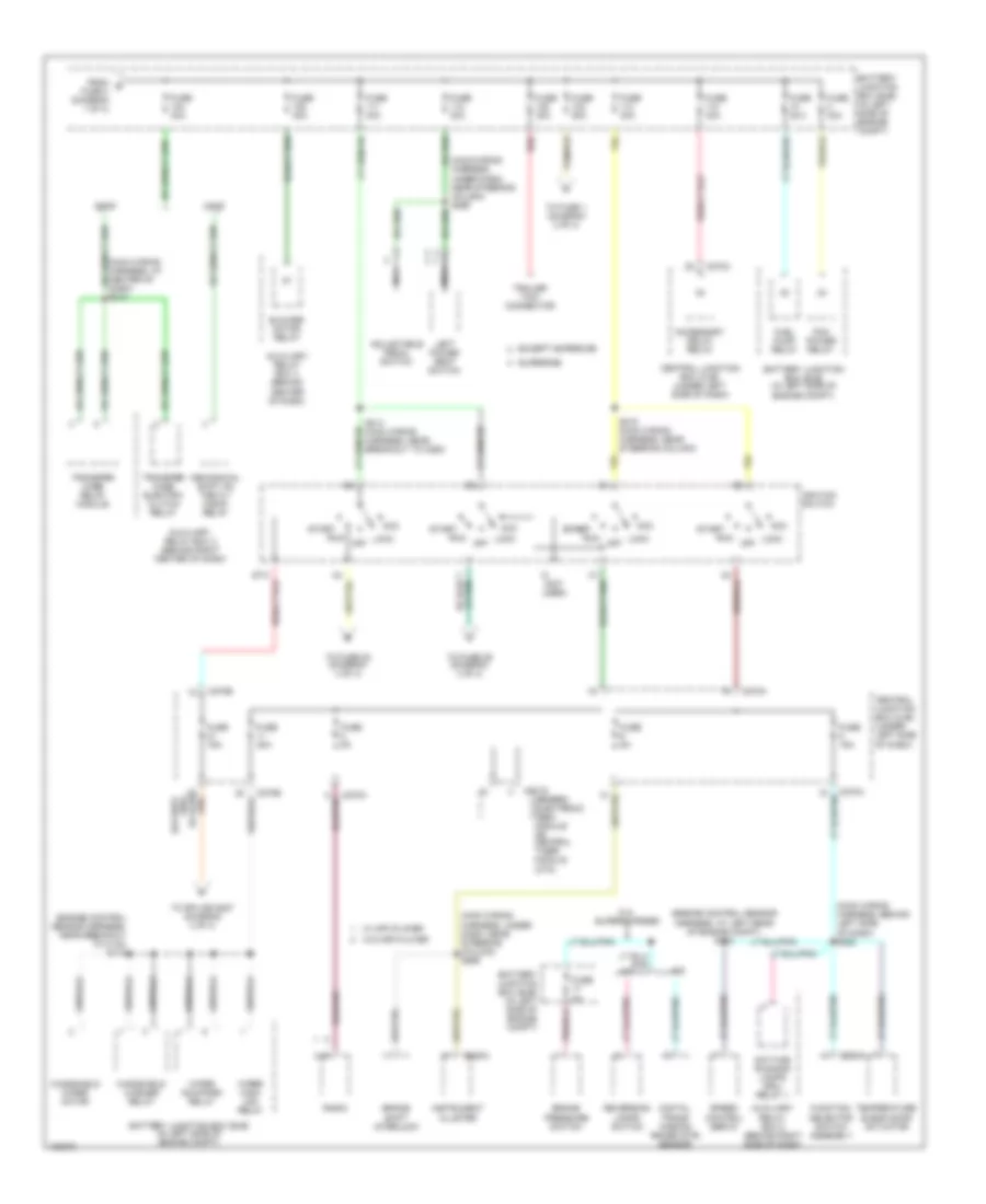
Power Distribution Wiring Diagram (1 of 4) for Ford Pickup Heritage F150 2004


List of elements for Power Distribution Wiring Diagram (1 of 4) for Ford Pickup Heritage F150 2004:
- (engine control sensor harness, at left front of engine compt) s171
- (engine control sensor harness, at left rear of engine compt) s109
- (main wiring harness, near steering column) s212
- (main wiring harness, under dash, near steering column) (w/ autolamps) s241
- (starter motor relay & battery ground harness, at right front of engine compt) s1001
- 5.4l
- A/c clutch relay
- Abs control module
- Auxiliary relay box 3 (behind right center of dash)
- Battery
- Battery junction box (bjb) (in left side of engine compt)
- Bi-fuel gas/lpg
- Bi-fuel power relay
- Bi-fuel relay module (in bi- fuel relay module)
- C102a
- C202b
- C205b
- C274b
- Central security module
- Charge air cooler pump relay
- Cold start heater relay
- Compuvalve module
- Daytime running lamps resistor
- Fog lamp relay
- From a fuse 8 (diagram 1 of 4)
- Fuse 10a
- Fuse 15a
- Fuse 20a
- Fuse 30a
- Fuse 3a
- Fuse 50a
- Generator
- Headlamp relay (w/ autolamps)
- Horn relay
- Main light switch
- Multi- function switch
- Nca
- Park lamp relay (w/ autolamps)
- Power point (at center of dash)
- Red
- S1002 (starter motor relay & battery ground harness, at right front of engine compt)
- S108 (engine control sensor harness, at left rear of engine compt)
- Starter motor
- Starter relay
- To fuse 104 (diagram 2 of 4)
- To fuse 9 (diagram 1 of 4)
- To splice s205 (diagram 3 of 4)
- Trailer tow battery charge relay
- Trailer tow parking lamp relay
- Trailer tow reversing lamp relay
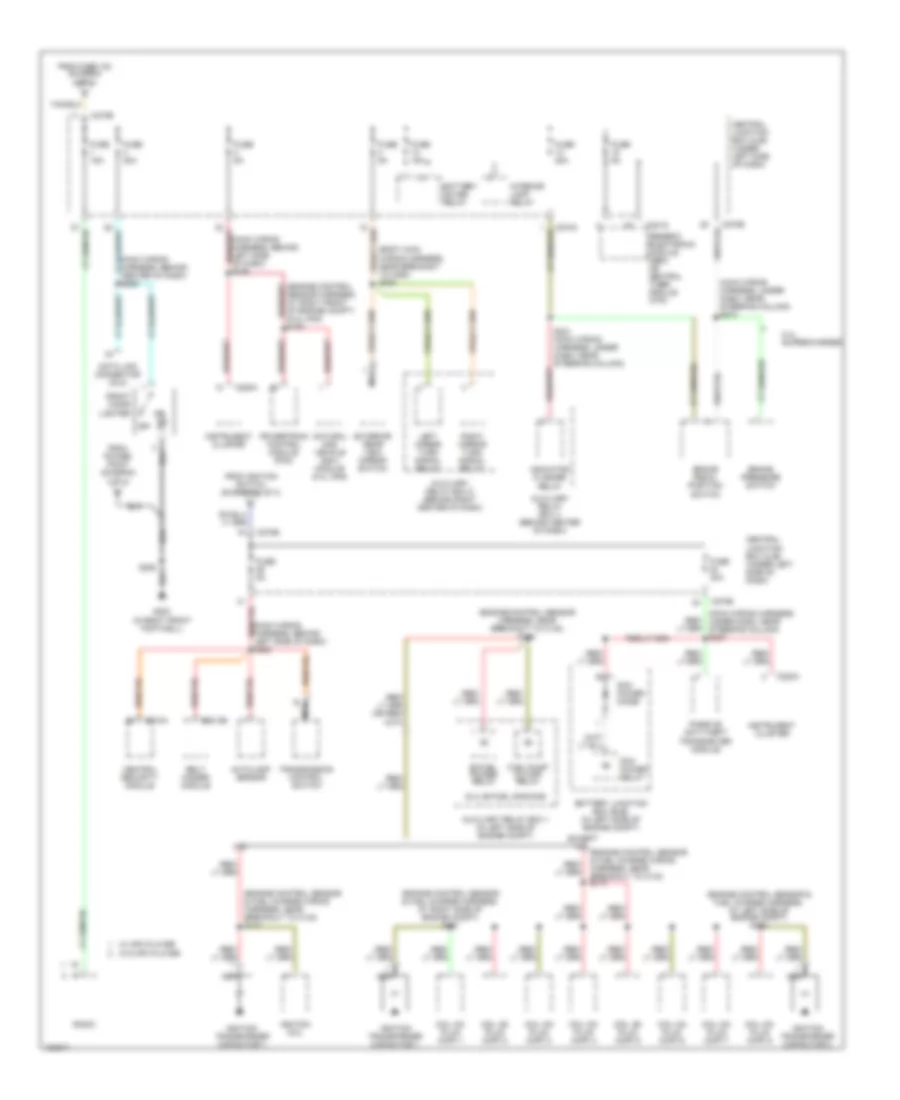
Power Distribution Wiring Diagram (2 of 4) for Ford Pickup Heritage F150 2004
List of elements for Power Distribution Wiring Diagram (2 of 4) for Ford Pickup Heritage F150 2004:
- (engine control sensor harness, at left rear of engine compt) s112
- (engine control sensor harness, near breakout to c140) s113
- (main wiring harness, at center of dash) s213
- (main wiring harness, behind left side of dash) s222
- (main wiring harness, under dash, near steering column) s265
- (not used)
- 5.4l supercharged
- A/t
- Acc
- Accessory delay relay
- Adjustable pedal switch
- Auxiliary relay box 2 (behind right side of dash)
- Auxiliary relay box 3 (behind right center of dash)
- Auxiliary relay box 4 (behind center of dash)
- Battery junction box (bjb) (in left side of engine compt)
- Blower motor relay
- Brake pressure switch
- Brake shift interlock
- C201d
- C220a
- C270a
- C270b
- C294a
- Central junction box (cjb) (under left side of dash)
- Daytime running lamps (drl) relay 1
- Digital trans- mission range (dtr) sensor
- Esof
- Except supercab
- From b fuse 3 (diagram 1 of 4)
- Fuel pump relay
- Function selector switch assembly
- Fuse 15a
- Fuse 20a
- Fuse 2a
- Fuse 30a
- Fuse 40a
- Fuse 50a
- Fuse 5a
- Generic electronic (gem) module or central timer module (ctm)
- Ignition switch
- Instrument cluster
- Left power seat switch
- Lock
- M/t
- Mechanical shift on the fly (msof) relay
- Msof
- Nca
- Off
- Pcm power relay
- Radio
- Red
- Reversing lamps switch
- Run
- S214 (main wiring harness, near breakout to c263)
- S215 (main wiring harness, near steering column)
- Speed control servo
- Start
- Start start
- Supercab
- Temperature blend door actuator
- To fuse 1 (diagram 3 of 4)
- To fuse 22 (diagram 4 of 4)
- To fuse 29 (diagram 3 of 4)
- To splice s227 (diagram 4 of 4)
- Trailer tow connector
- Transfer case electric clutch relay
- Transfer case relay module
- W/ mp3 player
- W/o mp3 player
- Windshield washer relay
- Windshield wiper motor
- Wiper high/ low relay
- Wiper run/park relay
Power Distribution Wiring Diagram (3 of 4) for Ford Pickup Heritage F150 2004
List of elements for Power Distribution Wiring Diagram (3 of 4) for Ford Pickup Heritage F150 2004:
- (5.4l bi-fuel gas/cng)
- (body main wiring harness, near breakout to c260) s220
- (engine control sensor & fuel charge harness, at left side of engine compt) s162
- (engine control sensor & fuel charge harness, at right side of engine compt) s161
- (engine control sensor & fuel charge wiring harness, near breakout to c133) s117
- (engine control sensor harness, near breakout to c140) s116
- (main wiring harness, behind center of dash) s289
- (main wiring harness, behind left side of dash) s225
- (main wiring harness, behind left side of dash) s236
- (main wiring harness, under dash, near steering column) s237
- (main wiring harness, under dash, near steering column) s274
- 4.2l
- 5.4l supercharged
- Autolamp sensor
- Auxiliary relay box 1 (in left side of engine compt)
- Auxiliary relay box 4 (behind center of dash)
- Auxiliary relay box 5 (behind right center of dash)
- Battery junction box (bjb) (in left side of engine compt)
- Battery saver relay
- Belt minder module
- Bi-fuel power relay
- Brake pedal position switch
- Brake pressure switch
- C2013b
- C201d
- C220a
- C270a
- C270b
- C274a
- Central junction box (cjb) (under left side of dash)
- Central security module
- Coil on plug (cop) 1
- Coil on plug (cop) 2
- Coil on plug (cop) 3
- Coil on plug (cop) 4
- Coil on plug (cop) 5
- Coil on plug (cop) 6
- Coil on plug (cop) 7
- Coil on plug (cop) 8
- Data link connector (dlc)
- Except 4.2l
- Exterior rear view mirror switch
- From fuse 103 (diagram 2 of 4)
- From ignition switch (diagram 2 of 4)
- From power point (diagram 1 of 4)
- Front cigar lighter
- Fuel pump cutoff relay
- Fuse 15a
- Fuse 20a
- Fuse 30a
- Fuse 5a
- G203 (in right front footwell)
- Generic electronic module (gem) or central timer module (ctm)
- Ignition coil
- Ignition transformer capacitor 1
- Ignition transformer capacitor 2
- Indicator flasher relay
- Instrument cluster
- Interior lamp relay
- Left mirror turn signal relay
- Natural gas vehicle (ngv) module (5.4l cng)
- Nca
- Off
- Passive anti-theft transceiver module
- Pcm power diode
- Pcm power relay
- Powertrain control module (pcm)
- Radio
- Right mirror turn signal relay
- S158
- S205
- S221 (main wiring harness, under dash, near steering column)
- Transmission control switch
- W/ mp3 player
- W/o mp3 player
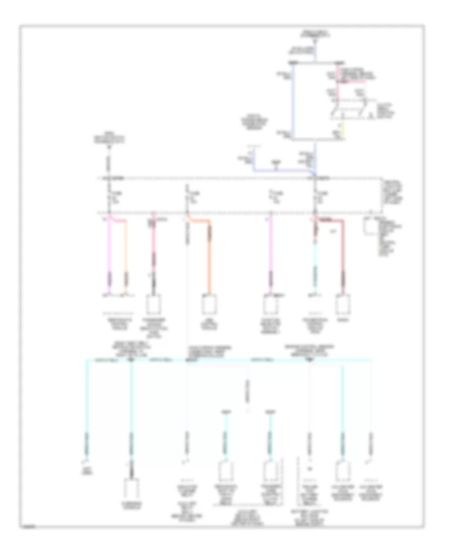
Power Distribution Wiring Diagram (4 of 4) for Ford Pickup Heritage F150 2004
List of elements for Power Distribution Wiring Diagram (4 of 4) for Ford Pickup Heritage F150 2004:
- (engine control sensor harness, near breakout to c140) s120
- (main wiring harness, behind left side of dash) s227
- (main wiring harness, under dash, near steering column) s228
- (not used)
- (right seat belt retractor switch harness, at right "b" pillar) s311
- 4x2 center axle disconnect solenoid
- 4x4 center axle disconnect solenoid
- Abs control module
- Auxiliary relay box 3 (behind right center of dash)
- Auxiliary relay box 4 (behind center of dash)
- Battery junction box (bjb) (in left side of engine compt)
- C201d
- C207b
- C270b
- C294a
- Central junction box (cjb) (under left side of dash)
- Clutch pedal position switch
- Digital transmission range (dtr) sensor
- Esof
- From fuse 21 (diagram 2 of 4)
- From ignition switch (diagram 2 of 4)
- Function selector switch assembly
- Fuse 10a
- Fuse 5a
- Generic electronic module (gem) or central timer module (ctm)
- Indicator flasher relay
- M/t
- Mechanical shift on the fly (msof) relay
- Msof
- Nca
- Overhead console
- Passenger air bag deactivation (pad) switch
- Powertrain control module (pcm)
- Radio
- Restraints control module
- Tan/red
- Trailer tow battery charge relay
- Transfer case electric clutch relay

 Čeština
 Dansk
Dansk Deutsch
 Ελληνικά
 English
 English
 Español
 Français
 Français
 עברית
עברית Hrvatski
 Magyar
 Italiano
 日本語
日本語 한국어
한국어 Nederlands
 Polski
 Português
 Português
 Română
 Русский
 Slovenčina
 Slovenščina
 Svenska
 Türkçe
 中文 (中国)