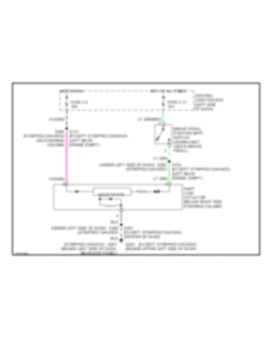
SHIFT INTERLOCKS
Shift Interlock Wiring Diagram for Ford Econoline E350 Super Duty 2002
List of elements for Shift Interlock Wiring Diagram for Ford Econoline E350 Super Duty 2002:
- (except stripped chassis)
- (stripped chassis)
- (under left side of dash)
- Brake pedal position (bpp) switch (on bracket, above brake pedal)
- Central junction box (left side of dash)
- Fuse 2.11 15a
- Fuse 2.6 10a
- G203 (behind upper left side of dash)
- G207 (behind left side of dash, near kick panel)
- Hot at all times
- Hot in run
- S131 (except stripped chassis) (left rear engine compt)
- S207 (except stripped chassis) (center of dash)
- S282 (stripped chassis) (on steering column)
- S283 (stripped chassis)
- S286 (stripped chassis)
- Shift lock actuator (below right side steering column)
- Solid state
 Čeština
 Dansk
Dansk Deutsch
 Ελληνικά
 English
 English
 Español
 Français
 Français
 עברית
עברית Hrvatski
 Magyar
 Italiano
 日本語
日本語 한국어
한국어 Nederlands
 Polski
 Português
 Português
 Română
 Русский
 Slovenčina
 Slovenščina
 Svenska
 Türkçe
 中文 (中国)
 Suomi
Suomi