WARNING SYSTEMS
Warning System Wiring Diagrams for Oldsmobile Intrigue GL 2002
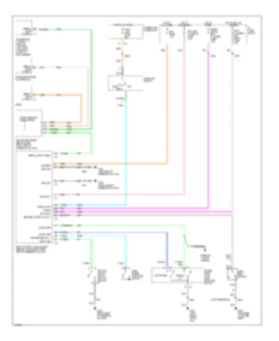
List of elements for Warning System Wiring Diagrams for Oldsmobile Intrigue GL 2002:
- (w/ power seats)
- B10
- B11
- Battery
- Bcm fuse 10a
- Body control module (bcm) (behind left side of dash, left of steering column)
- Computer data lines system
- Crank
- Crank signal, bcm cluster fuse 10a
- Door ajar
- Driver door lock (ajar indicator switch)
- G201 (left side of steering column)
- G203 (right side of steering column)
- G301 (forward of driver seat)
- G301 (left front door sill)
- Ground
- Handle
- Head
- Headlamp switch
- Hot at all times
- Hot in acc, on & start
- Hot in on & start
- Hot in start
- I/p fuse block
- Ign 0, cluster, pcm & bcm fuse 10a
- Ignition 0
- Ignition 1
- Ignition switch (key in ignition switch) c2
- Instrument panel cluster (ipc)
- Interior lights system
- Key in ign
- Nca
- Off
- Park
- Park brake (ign 1)
- Park brake indicator switch
- Park lamp fuse 20a
- Park lp off
- Pcm, bcm u/h relay fuse 10a
- Pnk
- Powertrain control module (left side of engine compt, in air cleaner)
- Radio
- S211
- S234
- S270
- S283
- S296
- S333
- S504
- Seat belt switch
- Seat belt switch (ign 1)
- Serial data class 2
- Splice pack sp205 (below dash, right side of steering column)
- Underhood fuse block
- Unlatched
 Čeština
 Dansk
Dansk Deutsch
 Ελληνικά
 English
 English
 Español
 Français
 Français
 עברית
עברית Hrvatski
 Magyar
 Italiano
 日本語
日本語 한국어
한국어 Nederlands
 Polski
 Português
 Português
 Română
 Русский
 Slovenčina
 Slovenščina
 Svenska
 Türkçe
 中文 (中国)
 Suomi
Suomi