STARTING/CHARGING
Charging Wiring Diagram for Pontiac GTO 2004
 https://portal-diagnostov.com/license.html
Automotive Electricians Portal FZCO
Automotive Electricians Portal FZCO
https://portal-diagnostov.com/license.html
https://portal-diagnostov.com/license.html
Automotive Electricians Portal FZCO
Automotive Electricians Portal FZCO
List of elements for Charging Wiring Diagram for Pontiac GTO 2004:
- Bat pos voltage
- Battery
- C2 generator
- Charge ind ctrl
- Charge warning ind
- Fusible link
- G100
- G101
- Heated rear window, hvac & instruments fuse 7.5a
- Hot at all times
- Hot in run or start
- Ign pos voltage
- Instrument panel cluster (ipc)
- Instrument panel fuse block (below left end of dash)
- Instruments fuse 10a
- Power distribution system
- Red
- S207
- Starter
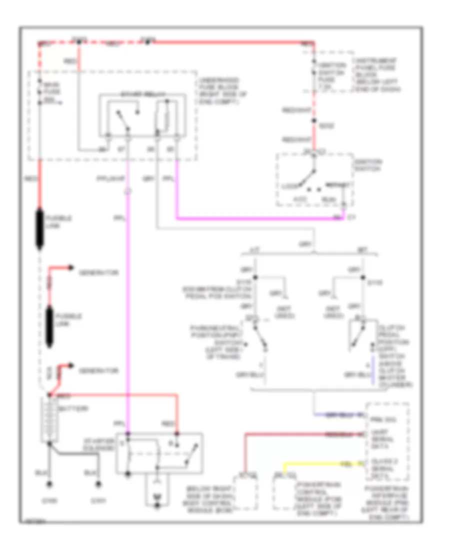
Starting Wiring Diagram for Pontiac GTO 2004
List of elements for Starting Wiring Diagram for Pontiac GTO 2004:
- (below right side of dash) body control module (bcm)
- (not used)
- A/t
- Acc
- Battery
- Class 2 serial data
- Clutch pedal position (cpp) switch (above clutch master cylinder)
- Fusible link
- G100
- G101
- Generator
- Ignition switch
- Ignition switch fuse 7.5a
- Instrument panel fuse block (below left end of dash)
- Lock
- M/t
- Main fuse 60a
- Nca
- Park/neutral position (pnp) switch (left side of trans)
- Powertrain control module (pcm) (left side of eng compt)
- Powertrain interface module (pim) (left rear of eng compt)
- Prk sig
- Red
- Run
- S103
- S104
- S115
- S115 (550 mm from clutch pedal pos switch)
- S202
- Start
- Start relay
- Starter solenoid
- Uart serial data
- Underhood fuse block (right side of eng compt)
 Čeština
 Dansk
Dansk Deutsch
 Ελληνικά
 English
 English
 Español
 Français
 Français
 עברית
עברית Hrvatski
 Magyar
 Italiano
 日本語
日本語 한국어
한국어 Nederlands
 Polski
 Português
 Português
 Română
 Русский
 Slovenčina
 Slovenščina
 Svenska
 Türkçe
 中文 (中国)
 Suomi
Suomi