СИСТЕМА АНТИБЛОКИРОВОЧНОЙ ТОРМОЗНОЙ СИСТЕМЫ ABS
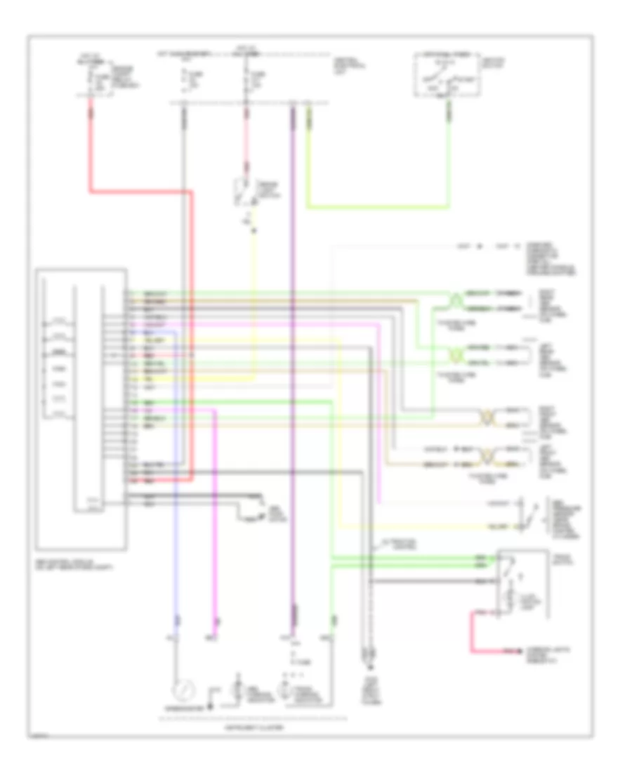
Электросхема антиблокировочной тормозной системы АБС (ABS) для Volvo V70 T-5 1998
Электросхема антиблокировочной тормозной системы АБС (ABS) для Volvo V70 T-5 1998 - Список элементов:
- 15a
- A18
- A29
- Abs control module (on left rear of eng compt)
- Abs pump motor
- Abs warning indicator
- Acc
- Brake light switch
- Central electrical unit
- Control
- Ebd pressure sensor (near brake master cylinder)
- Engine compt relay/ fuse box
- Fuse
- Fuse a4 15a
- Fuse c11 10a
- Fuse c3 10a
- G102 (left front strut tower)
- Hot at all times
- Hot in on or start
- Ignition switch
- Illum- ination lamp
- Instrument cluster
- Interior lights system (rheostat)
- Left front abs sensor (on wheel hub)
- Left rear abs sensor (on wheel hub)
- M (+)
- M (-)
- Nca
- Off
- On-board diagnostic connector (partial) (center console, forward shifter)
- Pnk
- Red
- Right front abs sensor (on wheel hub)
- Right rear abs sensor (on wheel hub)
- Speedometer
- Start
- Tracs switch
- Tracs warning indicator
- Twisted wire pairs
- W/ traction
 Čeština
 Dansk
Dansk Deutsch
 Ελληνικά
 English
 English
 Español
 Français
 Français
 עברית
עברית Hrvatski
 Magyar
 Italiano
 日本語
日本語 한국어
한국어 Nederlands
 Polski
 Português
 Português
 Română
 Русский
 Slovenčina
 Slovenščina
 Svenska
 Türkçe
 中文 (中国)
 Suomi
Suomi