INSTRUMENT CLUSTER
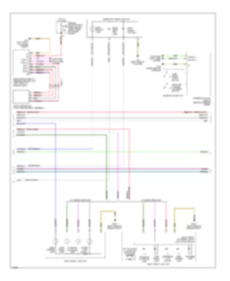
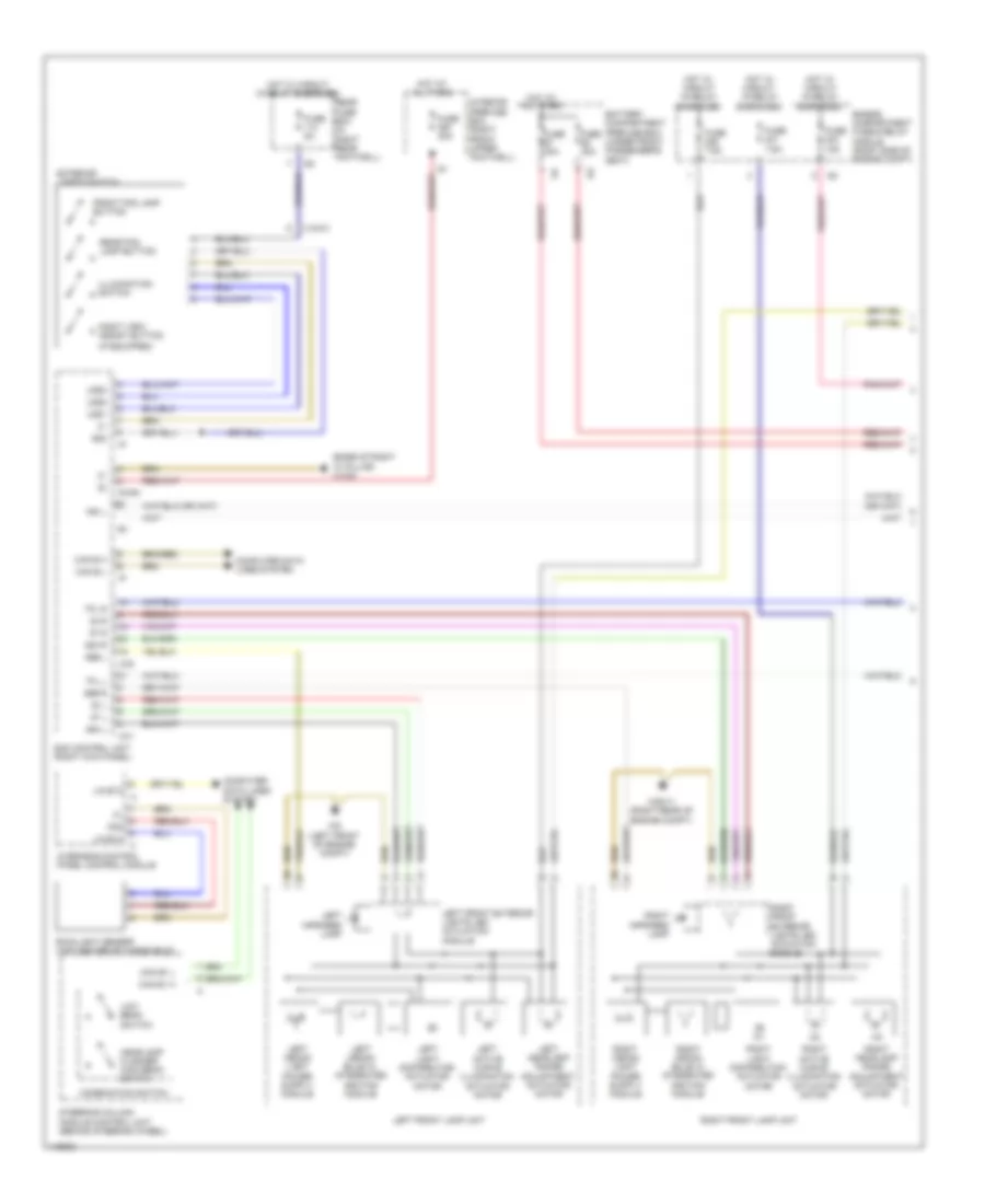
Instrument Cluster Wiring Diagram (1 of 2) for Mercedes-Benz C250 2012
List of elements for Instrument Cluster Wiring Diagram (1 of 2) for Mercedes-Benz C250 2012:
- Active curve illumination actuator motor
- Bls h
- Bls l
- Bls m
- Can e1 h
- Can e1 l
- Can-h h
- Can-h l
- Combination switch
- Computer data lines system
- Cornering illumi- nation
- Electronic stability program control unit (left front of engine compt)
- Engine compartment prefuse box (right rear of engine compt)
- Fuse 40a
- Headlamp flasher/ high beam switch
- Hot at all times
- Infrared lamp
- Inner right rear lamp unit
- Outer turn signal lamp
- Right backup lamp
- Right front exterior lights actuation module
- Right front lamp unit
- Right inside taillight
- Right rear fog lamp
- Side- marker lamp
- Standing & parking lamp
- Steering column module (behind steering wheel)
- Stop lamp switch (top of brake pedal assembly)
- Turn signal lamp
- Turn signal lamps switch
- W/ xenon headlamp
- W/0 xenon headlamp
- W1/4 (under center console)
- W52/11 (right rear of engine compt)
- W70 (left front of engine compt)
- W8 (right side of tailgate)
- X25/2 c1
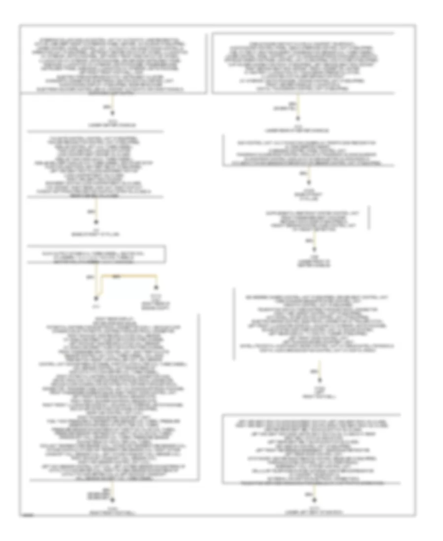
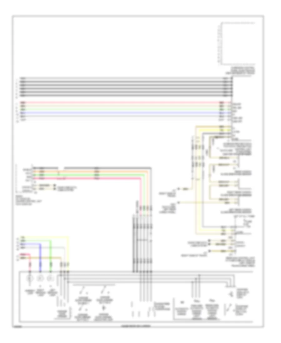
Instrument Cluster Wiring Diagram (2 of 2) for Mercedes-Benz C250 2012
List of elements for Instrument Cluster Wiring Diagram (2 of 2) for Mercedes-Benz C250 2012:
- & lane keeping assist), overhead control panel control unit, panoramic sliding roof control module (w/ panoramic sliding sunroof) sliding roof control module (w/ glass electric sliding roof) & ata (edw)/towing sensor/interior motion sensor control unit (if equipped)
- 360 degree camera control unit (if equipped), driver seat control unit, video & radar sensor system control unit, airmatic control unit (if equipped), telematics can voltage distributor electrical connector, night view assist control unit (if equipped), active roll stabilization control unit (if equipped), electric brake control electrical connector (w/ trailer hitch), left front illuminated door sill molding (w/ interior lights package), sound system amplifier control unit (w/ sound system), left rear display, tv digital turner (if equipped), left front door control unit, left running board courtesy light, satellite digital audio radio (sdar) control unit (w/ sirius satellite radio) & digital audio broadcasting control unit (w/ digital radio)
- Glove box lamp switch
- Glow output stage (3.0l turbo diesel), ignition coil cylinders 1, 2, 3, 4, 5, 6, 7 & 8 (4.6l turbo) & ignition coil cylinders 1, 2, 3, 4, 5 & 6 (3.5l)
- Left 3rd seat row folding backrest switch (left 2nd seat row) (gl-class), right 3rd seat row folding backrest switch (right 2nd seat row) (gl-class), center rear seat belt buckle switch (gl-class), left 2nd seat row easy entry/exit switch (gl class & w/ rear seat belt status indication), left rear seat belt buckle switch (gl-class), keyless go control unit (if equipped), left front reversible emergency tensioning retractor, left rear door control unit, stationary heater radio remote control receiver (if equipped), parking system control unit (w/ parktronic), emergency call system control unit, cellular telephone system antenna amplifier/compensator (w/ comfort telephony) & external navigation electrical connector & telematics services communication module (w/ live traffic information)
- Mobile phone contact plate (w/ comport telephony), audio/comand control panel, media interface control unit (if equipped), fuel filter w/ heating element condensation sensor (3.0l turbo diesel), lower control panel control unit (w/ on-road/off-road package & airmatic), off-road operating panel control unit (if equipped), dvd player (if equipped), cup holder connecting point (if equipped), left second seat row socket, right second seat row socket, front cigarette lighter w/ ashtray illumination (w/ tacho graph preinstallation), illuminated cup holder separation point (w/ interior lights package), comand control unit (if equipped) front center console illumination & digital tachograph control unit (if equipped)
- Right rear display, driver side bag squib, potential distributor electrical connector (can i), vehicle floor chassis can e1 potential distributor electrical connector, right exhaust gas recirculation hall sensor (w/ gasoline direct injection & stratified charge), left exhaust gas recirculation hall sensor (w/ gasoline direct injection & stratified charge), front passenger seat control unit, soot particulate sensor control unit (3.0l turbo diesel), collision prevention assist controller unit, nox sensor control unit downstream of diesel particulate filter (3.0l turbo diesel), nox sensor control unit downstream of scr catalytic converter (3.0l turbo diesel), right potential distributor electrical connector (can), drive train can voltage distributor electrical connector, vehicle floor chassis can e2 potential distributor electrical connector, transfer case control unit (w/ on-road/off-road package), front passenger sidebag squib, right front door control unit, left front bumper distronic sensor (dtr), right front bumper distronic sensor (dtr), right front illuminated door sill molding (w/ interior lights package), eco start/stop function diode (if equipped), me-sfi (me) control unit (3.5l), right running board courtesy light, fuel tank pressure & temperature sensor (4.6l turbo), pressure sensor downstream of air filter (4.6l turbo), pressure sensor downstream of throttle valve (4.6l turbo), pressure sensor upstream of throttle valve (4.6l turbo), crankshaft hall sensor (4.6l turbo), pressure sensor downstream of air filter (4.6l turbo), coolant temperature sensor (3.5l), intake air temperature sensor (3.5l), intake manifold intake air temperature sensor (3.5l), right intake camshaft hall sensor (3.5l), left intake camshaft hall sensor (3.5l), right exhaust camshaft hall sensor (3.5l), right nox sensor control unit (3.5l), left nox sensor control unit (3.5l), left oxygen sensor downstream of catalytic converter (3.5l), right oxygen sensor downstream of catalytic converter (3.5l) & left exhaust camshaft hall sensor (except 3.ol turbo diesel)
- Sam control unit, multi-function camera (w/ traffic sign recognition
- Steering column module control unit (w/ automatic lane recognition, active lane keep assist & steering wheel heater), ac housing (if equipped), upper control panel control unit, automatic air conditioning control & operating unit (if equipped), left/right center air outlet symbol illumination (w/ interior lights package), left/right front side air outlet symbol illumination (w/ interior lights package), driver side instrument panel ambiance illumination (w/ interior lights package), passenger side instrument panel ambiance illumination (w/ interior lights package), left/right front footwell lamp, electric parking brake switch, instrument cluster, diagnostic connector, electronic ignition switch control unit, audio/comand display (if equipped), booster blower electronic blower controller (w/ comfort automatic air conditioning) &
- W1/4 (under center console)
- W11
- W11/2 (3.5l) (right rear of engine compt)
- W12 (under rear of center console)
- W15/1 (right front footwell)
- W15/2 (left front footwell)
- W17/1 (under left seat of 2nd row)
- W18/5 (base of right "a" pillar)
- W26 (under front of center console)
- W7 (base of right "d" pillar)
Overhead Console Wiring Diagram, with Sunroof (1 of 2) for Mercedes-Benz C250 2012
List of elements for Overhead Console Wiring Diagram, with Sunroof (1 of 2) for Mercedes-Benz C250 2012:
- (center front of trunk) emergency call system control unit
- 15r
- 30g
- 58d
- C13d
- C15m
- C19i
- Can b h
- Can b l
- Computer data lines system
- Front dome lamp switch
- Front sam control unit w/ fuse & relay module (left rear of engine compt)
- Fuse 30a
- Hot w/ quiescent current cutout relay energized
- Hs (+)
- Hs 1
- Hs 2
- Info
- Info led
- Interior lamp automatic function switch
- Interior lights system
- Interior protection switch (w/ tow-away protection & interior protection)
- Interior temperature sensor w/ integrated fan
- Left front interior lamp
- Left front reading lamp switch
- Lin 2
- Ll l 12v
- Ll r 12v
- Motor +
- Motor -
- Overhead control panel control unit (center rear of trunk)
- Pnk
- Power tops system
- Rear dome lamp switch
- Red
- Right front interior lamp
- Right front reading lamp switch
- Sos
- Sos led
- Tilting/ sliding roof switch
- Towing sensor button (w/ tow-away protection & interior protection)
- W16/3 (left side of engine compt)
- W18/3 (under dirver's seat)
- Ws led
- X18/37
Overhead Console Wiring Diagram, with Sunroof (2 of 2) for Mercedes-Benz C250 2012
List of elements for Overhead Console Wiring Diagram, with Sunroof (2 of 2) for Mercedes-Benz C250 2012:
- (not used)
- 58d
- Ambient lamp
- Ass led
- Ass off
- Automatic dimming mirror
- C5h
- C7i
- C8d
- Can b h
- Can b l
- Compass display button
- Compass module w/ display (if equipped)
- Computer data lines system
- Forward automatic dimming mirror light sensor
- Fuse 7.5a
- Garage door opener
- Garage door opener button 1
- Garage door opener button 2
- Garage door opener button 3
- Garage door opener indicator lamp
- Gnd
- Hands-free system microphone
- Hot at all times
- Inside rearview mirror
- Interior protection & tow-away protection control unit (if equipped) (center front of roof)
- Interior protection receiver (integral to interior protection & tow-away protection control unit)
- Irs led
- Irs-off
- Left interior protection transmitter (integral to interior protection & tow-away protection control unit)
- Left reading lamp
- Light sensor (w/o rain/light sensor) rain/light sensor (w/ rain/light sensor) (top center of windshield)
- Lin b4
- Mic 1
- Mic 2
- Nca
- Pnk
- Radio (w/ audio 20) comand control unit (w/o audio 20)
- Rear sam control unit w/ fuse & relay module (left side of trunk/cargo area)
- Rearward automatic dimming mirror light sensor
- Red
- Right interior protection transmitter (integral to interior protection & tow-away protection control unit)
- Right reading lamp
- Shield
- W7 (right side of trunk)
- X18/2
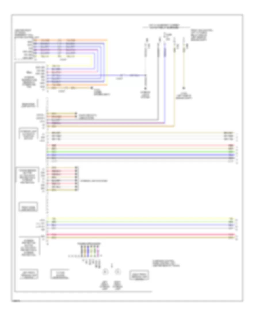
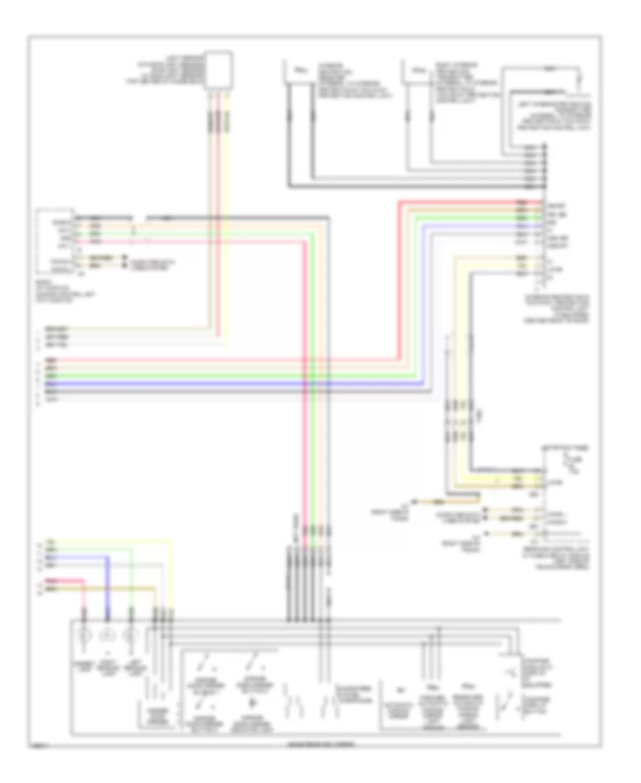
Overhead Console Wiring Diagram, without Sunroof (1 of 2) for Mercedes-Benz C250 2012
List of elements for Overhead Console Wiring Diagram, without Sunroof (1 of 2) for Mercedes-Benz C250 2012:
- (base of right "a" pillar) w18/5
- (if equipped)
- 30 l
- 30 r
- 30g
- 49a l
- 49a r
- 56b l
- 56b r
- 57 l
- 57 r
- 58d
- Battery compartment prefuse box (under front passenger's seat)
- Can b h
- Can b l
- Can e1 h
- Can e1 l
- Combination switch
- Computer data lines system
- Engine compartment fuse & relay module (right side of engine compt)
- Exterior lights switch
- Front fog lamp button
- Fuse 15a
- Fuse 30a
- Fuse 40a
- Fuse 5a
- Fuse 7.5a
- Headlamp flasher/ high beam switch
- Hot at all times
- Hot w/ circuit 15 relay energized
- Illumination switch
- Interior prefuse box (right front upper footwell)
- Lds1
- Lds2
- Lds3
- Left active curve illumination actuator motor
- Left front exterior lights led actuation module
- Left front lamp unit
- Left headlamp range adjustment actuator motor
- Left infrared lamp
- Left light distribution actuator motor
- Left xenon bulb w/ integrated ignition module
- Lin b13
- Low beam switch
- Night view assist button
- Nsi l
- Overhead control panel control module
- Pwr1
- Rain/light sensor (top center of windshield)
- Rear fog lamp button
- Rear fuse box (in right rear footwell)
- Right active curve illumination actuator motor
- Right front exterior lights led actuation module
- Right front lamp unit
- Right headlamp range adjustment actuator motor
- Right infrared lamp
- Right light distribution actuator motor
- Right xenon bulb w/ integrated ignition module
- Sam control unit (right kick panel)
- Steering column module control unit (behind steering wheel)
- Tfl l
- Tfl r
- Uh1
- Uh2
- W52/11 (right rear of engine compt)
- W9 (left front of engine compt)
- X18-c1
Overhead Console Wiring Diagram, without Sunroof (2 of 2) for Mercedes-Benz C250 2012
List of elements for Overhead Console Wiring Diagram, without Sunroof (2 of 2) for Mercedes-Benz C250 2012:
- (not used)
- 58d
- Ambient lamp
- Ass led
- Ass off
- Automatic dimming mirror
- C5h
- C7i
- C8d
- Can b h
- Can b l
- Compass display button (usa)
- Compass module w/ display (usa)
- Computer data lines system
- Forward automatic dimming mirror light sensor
- Fuse 7.5a
- Garage door opener
- Garage door opener button 1
- Garage door opener button 2
- Garage door opener button 3
- Garage door opener indicator lamp
- Glk-class
- Gnd
- Hands-free system microphone
- Hot at all times
- Inside rearview mirror
- Interior protection & tow-away protection control unit (if equipped) (center front of roof)
- Irs led
- Irs-off
- Left reading lamp
- Left rear window glass breakage sensor
- Lin b4
- Mic 1
- Mic 2
- Nca
- Overhead control panel electronics (center rear of trunk)
- Pnk
- Radio (w/ audio 20) comand control unit (w/o audio 20)
- Rear sam control unit w/ fuse & relay module (left side of trunk/cargo area)
- Rear window glass breakage sensor
- Rearward automatic dimming mirror light sensor
- Red
- Right reading lamp
- Right rear window glass breakage sensor
- S gb
- Shield
- W6/1 (glk class: left rear cargo panel)
- W7 (right side of trunk)
- X143/3
- X18/19
- X18/2

 Čeština
 Dansk
Dansk Deutsch
 Ελληνικά
 English
 English
 Español
 Français
 Français
 עברית
עברית Hrvatski
 Magyar
 Italiano
 日本語
日本語 한국어
한국어 Nederlands
 Polski
 Português
 Português
 Română
 Русский
 Slovenčina
 Slovenščina
 Svenska
 Türkçe
 中文 (中国)