AIR CONDITIONING
Air Conditioning Wiring Diagrams for Hyundai Sonata 1996
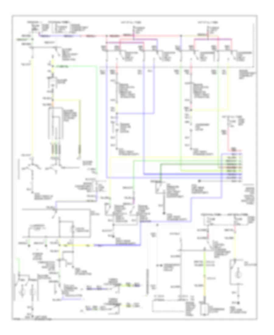
List of elements for Air Conditioning Wiring Diagrams for Hyundai Sonata 1996:
- (2.0l/l4)
- (l4)
- (left side of crash pad)
- (top of engine)
- (v6)
- A/c actuator
- A/c compressor clutch
- A/c control relay (in engine compartment fuse/relay box)
- A/c fuse 10a
- A/c low pressure switch (on accumulator)
- A/c on indicator
- A/c pressure switch (left front of engine compartment)
- A/c switch
- Blower actuator
- Blower motor
- Blower relay (below right side of crash pad)
- Blower resistors (right side of crash pad)
- Blower switch
- C01-4
- C01-6
- C51-4
- C51-6
- Condenser fan motor
- Condenser fan relay (high)
- Condenser fan relay (low)
- Dash fuse box
- Engine compartment fuse/relay box
- Engine control module (right kick panel)
- Engine coolant temp switch a (right side of radiator)
- Engine coolant temp switch b (right side of radiator)
- Engine cooling fan control module (right kick panel)
- Engine cooling fan motor
- Engine cooling fan motor resistor (right front of radiator)
- Fresh
- Fuse 10a
- Fuse 15a
- Fusible link d 30a
- Fusible link g 30a
- Fusible link k 20a
- G100 (left front of engine compt)
- G100 (right front of engine compt)
- G101 (right front of engine compt)
- G104 (left rear of engine compartment)
- G202
- G202 (left side of crash pad)
- Hot at all times
- Hot in on
- Iii
- Iiii
- Illumination
- Interior lights system
- Nca
- Off
- Radiator fan relay (high)
- Radiator fan relay (low)
- Rec
- Thermo sensor
- Thermostatic switch (right side of i/p)
- Transmission control module
 Čeština
 Dansk
Dansk Deutsch
 Ελληνικά
 English
 English
 Español
 Suomi
Suomi Français
 עברית
עברית Hrvatski
 Magyar
 Italiano
 日本語
日本語 한국어
한국어 Nederlands
 Polski
 Português
 Português
 Română
 Русский
 Slovenčina
 Slovenščina
 Svenska
 Türkçe
 中文 (中国)
 Français