Čeština
 Dansk
Dansk Deutsch
 Ελληνικά
 English
 English
 Español
 Suomi
Suomi Français
 עברית
עברית Hrvatski
 Magyar
 Italiano
 日本語
日本語 한국어
한국어 Nederlands
 Polski
 Português
 Português
 Română
 Русский
 Slovenčina
 Slovenščina
 Svenska
 Türkçe
 中文 (中国)

NAVIGATION
Front & Rear Camera Wiring Diagram for Hyundai Equus Signature 2013
List of elements for Front & Rear Camera Wiring Diagram for Hyundai Equus Signature 2013:

Lane Departure Warning Wiring Diagram (1 of 2) for Hyundai Equus Signature 2013
List of elements for Lane Departure Warning Wiring Diagram (1 of 2) for Hyundai Equus Signature 2013:
Lane Departure Warning Wiring Diagram (2 of 2) for Hyundai Equus Signature 2013
List of elements for Lane Departure Warning Wiring Diagram (2 of 2) for Hyundai Equus Signature 2013:
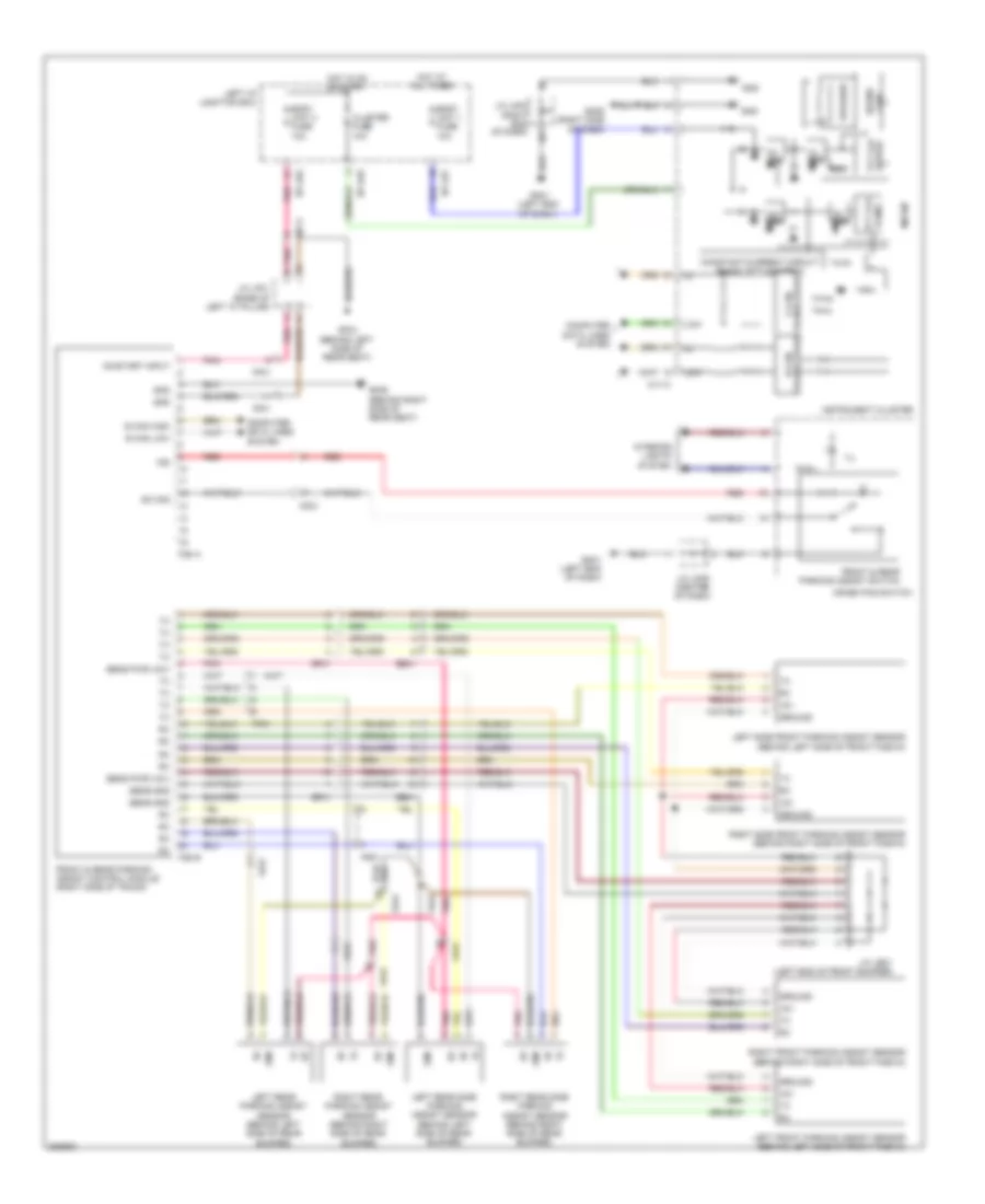
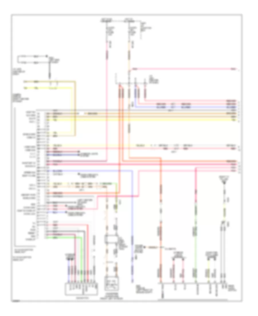
Navigation Wiring Diagram (1 of 4) for Hyundai Equus Signature 2013
List of elements for Navigation Wiring Diagram (1 of 4) for Hyundai Equus Signature 2013:
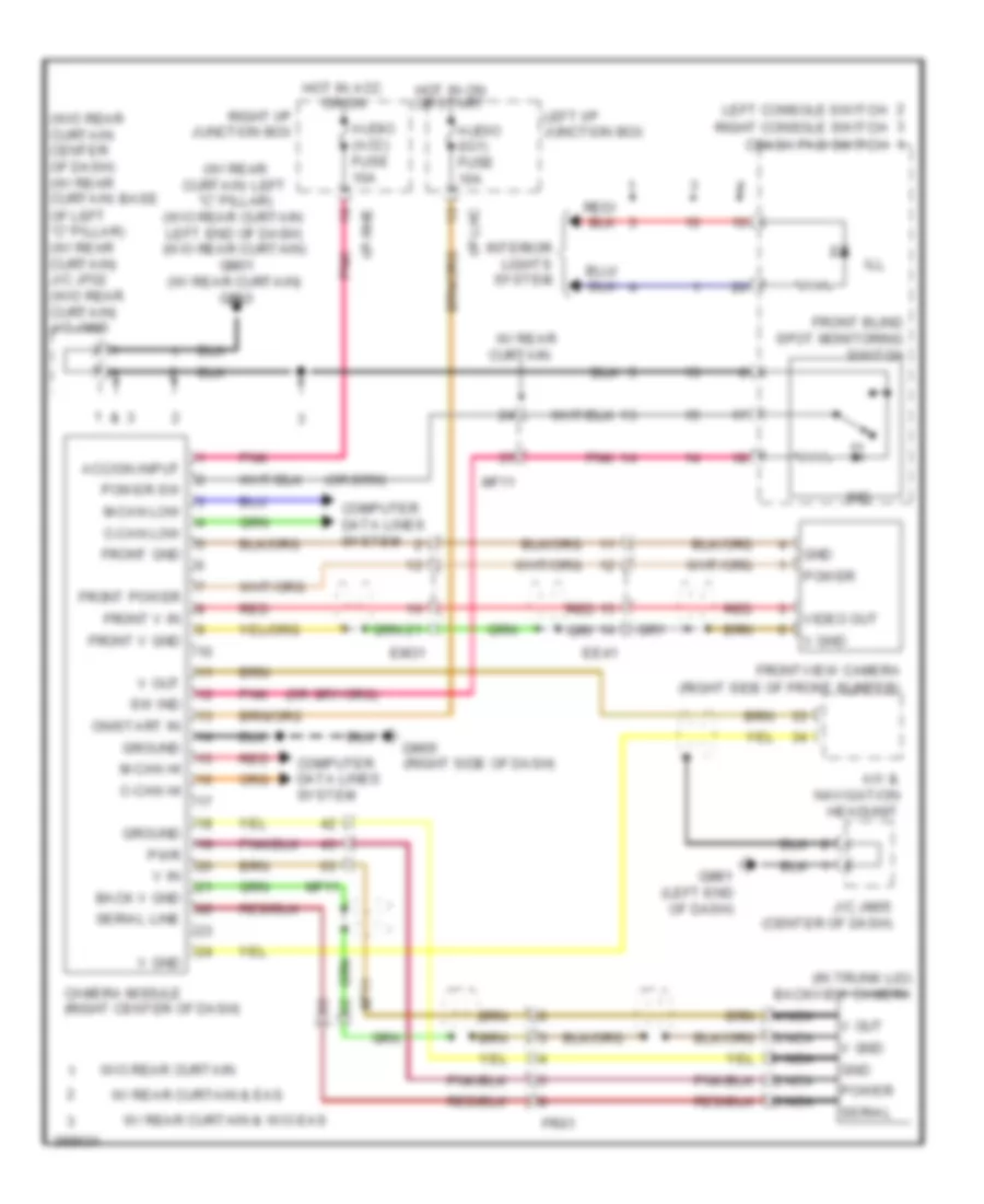
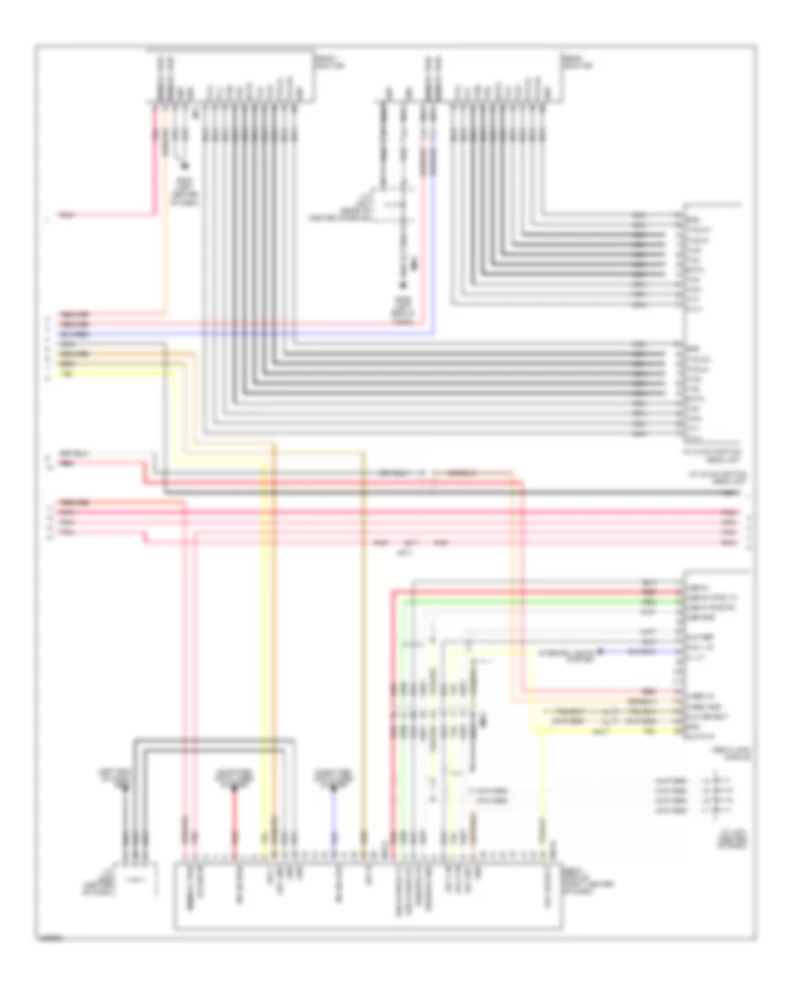
Navigation Wiring Diagram (2 of 4) for Hyundai Equus Signature 2013
List of elements for Navigation Wiring Diagram (2 of 4) for Hyundai Equus Signature 2013:
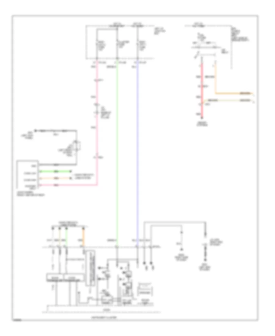
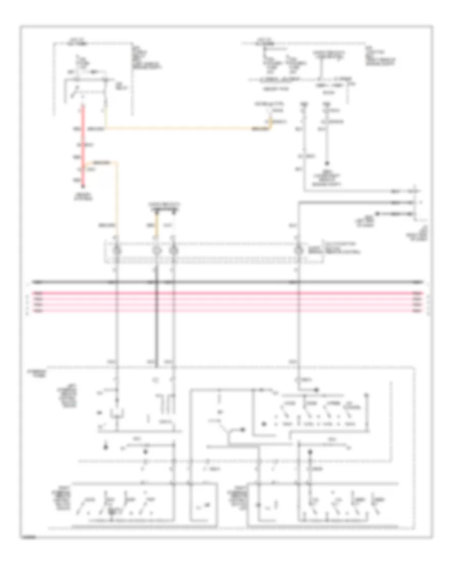
Navigation Wiring Diagram (3 of 4) for Hyundai Equus Signature 2013
List of elements for Navigation Wiring Diagram (3 of 4) for Hyundai Equus Signature 2013:
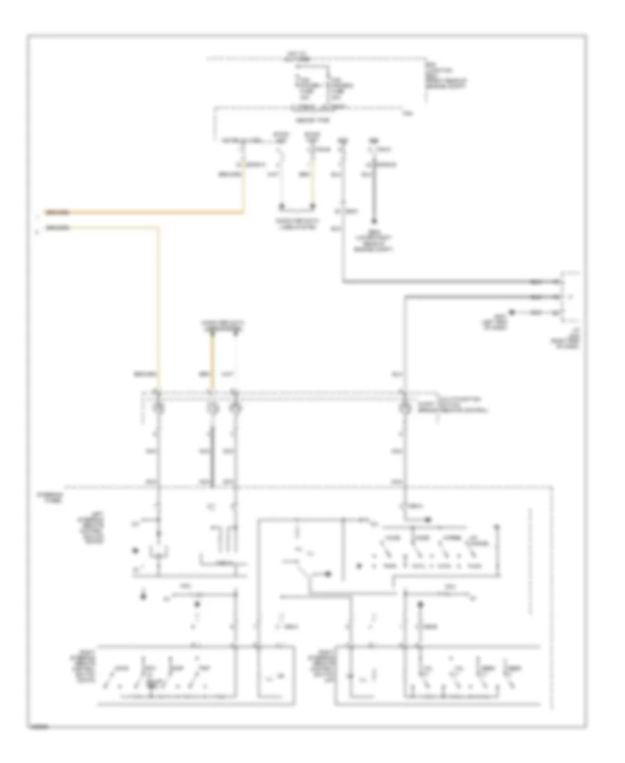
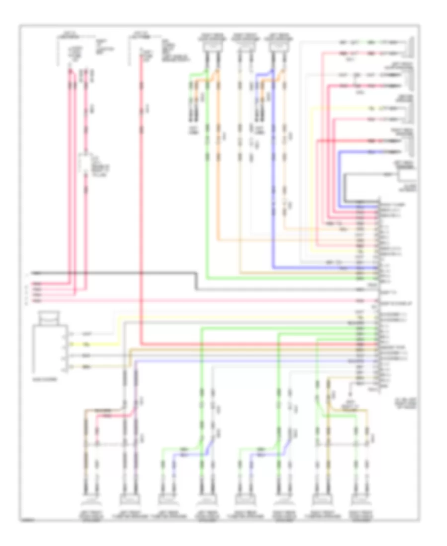
Navigation Wiring Diagram (4 of 4) for Hyundai Equus Signature 2013
List of elements for Navigation Wiring Diagram (4 of 4) for Hyundai Equus Signature 2013:
Parking Assistant Wiring Diagram for Hyundai Equus Signature 2013
List of elements for Parking Assistant Wiring Diagram for Hyundai Equus Signature 2013: