ENGINE PERFORMANCE
4.2L
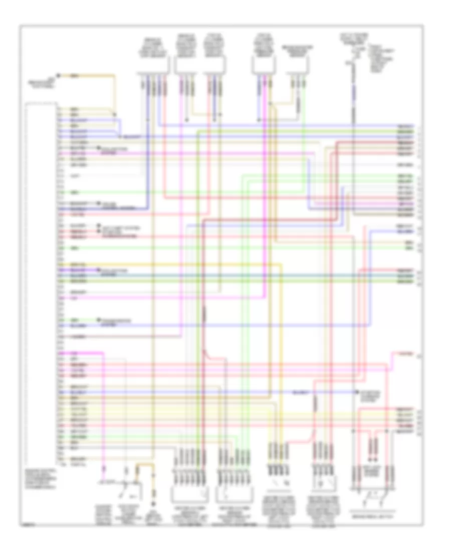
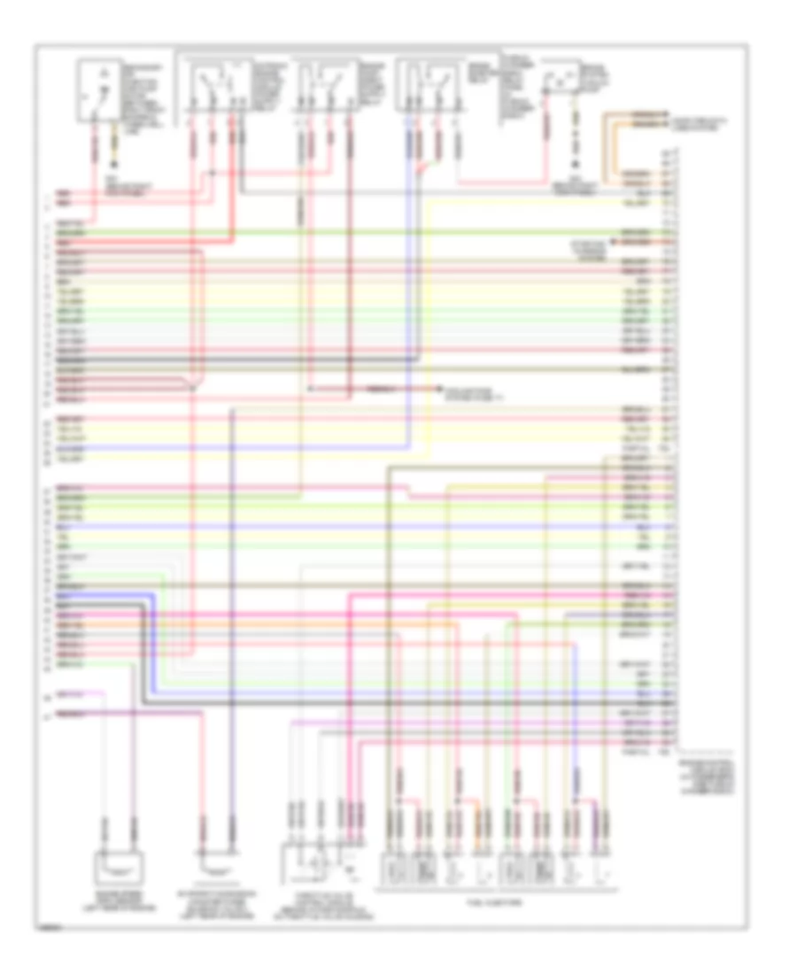
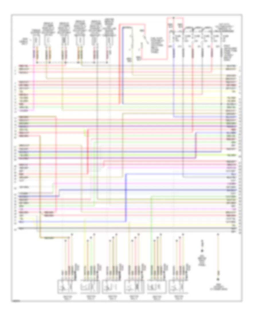
4.2L, Engine Performance Wiring Diagram (1 of 5) for Audi A8 L Quattro 2007
List of elements for 4.2L, Engine Performance Wiring Diagram (1 of 5) for Audi A8 L Quattro 2007:
- (rear of cylinder bank no 2) camshaft position sensor 4
- (rear of cylinder bank no. 1) mass air flow (maf) sensor
- (top of cylinder bank no 2) camshaft position sensor 2
- (top of cylinder bank no 2) low fuel pressure sensor
- Anti-lock brakes system
- Anti-theft system starting/ charging system
- Brake booster pressure sensor
- Brake pedal switch
- Comfort system central control module
- Cooling fans system
- Cruise control system
- Engine control module (ecm) (in passenger's side plenum chamber e-box)
- Fuse 5a
- G43 (behind right kick panel)
- G44 (behind left kick panel)
- Heated oxygen sensor (downstream of right 3-way catalytic converter)
- Heated oxygen sensor 2 (upstream of left 3-way catalytic converter)
- Heated oxygen sensor 2 behind 3-way catalytic converter (twc) (downstream of left 3-way catalytic converter)
- Heated oxygen sensor behind 3-way catalytic converter (twc) (downstream of right 3-way catalytic converter)
- Kick down switch (under accelerator pedal)
- Nca
- Partial
- Right instrument panel fuse panel (in right end of dash)
- Starting/ charging system
- T10q
- T94
- Transmissions system
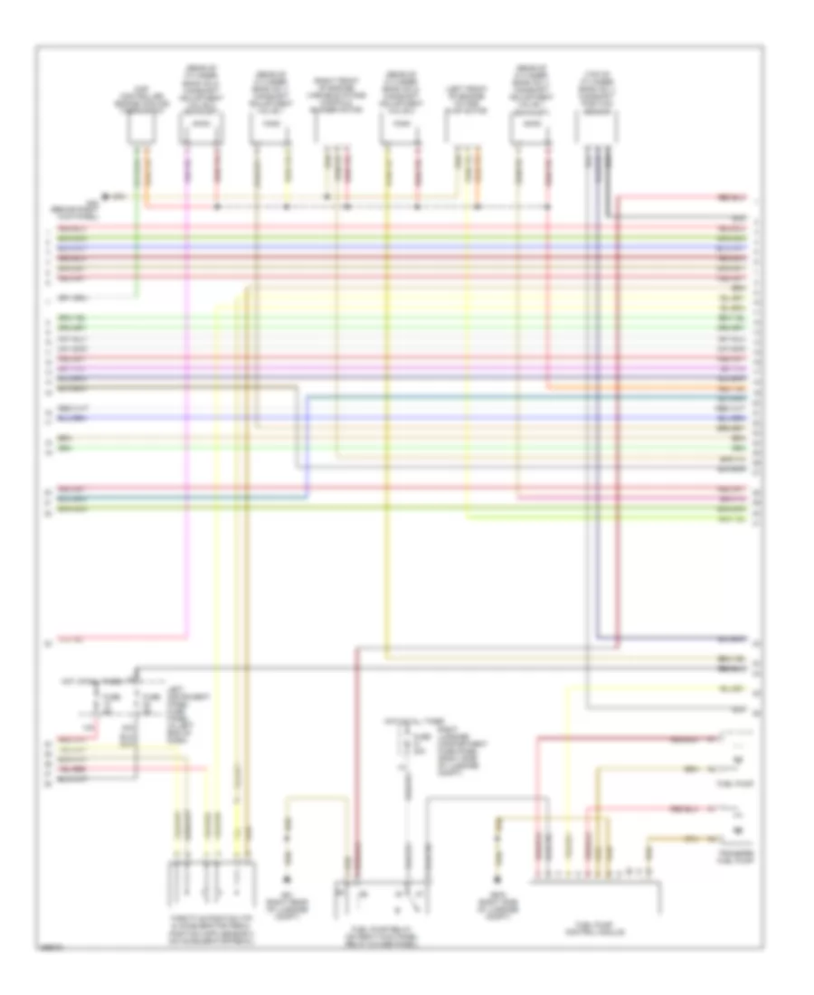
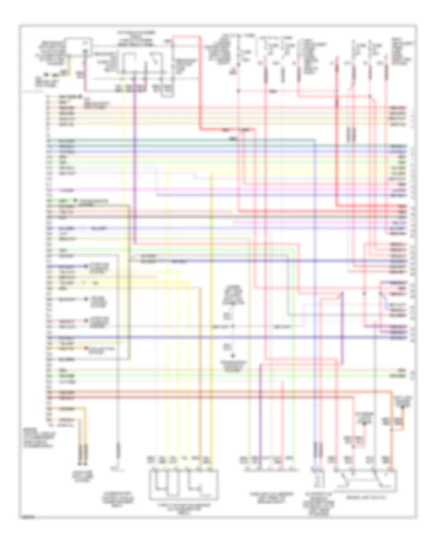
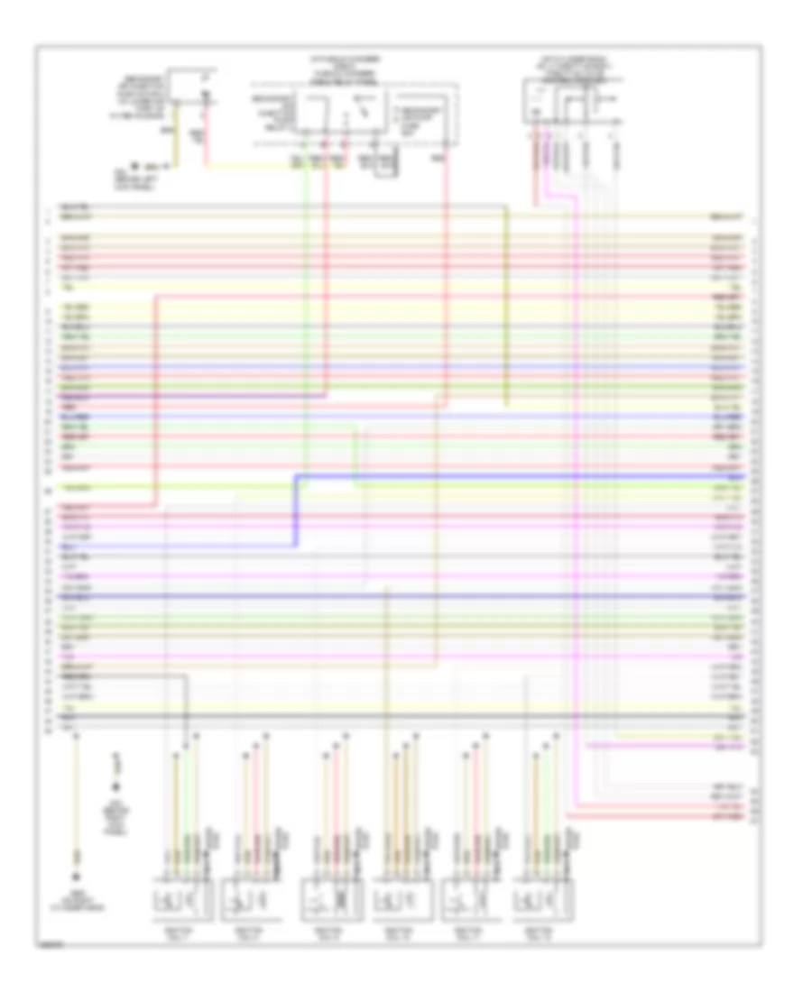
4.2L, Engine Performance Wiring Diagram (2 of 5) for Audi A8 L Quattro 2007
List of elements for 4.2L, Engine Performance Wiring Diagram (2 of 5) for Audi A8 L Quattro 2007:
- (left front of engine) intake flap motor
- (rear of cylinder bank no 1) camshaft adjustment valve 1
- (rear of cylinder bank no 1) camshaft adjustment valve 1 (exhaust)
- (rear of cylinder bank no 2) camshaft adjustment valve 2
- (rear of cylinder bank no 2) camshaft adjustment valve 2 (exhaust)
- (right front of engine) variable intake manifold runner motor
- (top of cylinder bank no 1) camshaft position sensor
- 12a
- 22a
- Fuel pump
- Fuel pump control module
- Fuel pump relay (on right kick panel relay & fuse panel)
- Fuse 40a
- Fuse 5a
- G43 (behind right kick panel)
- G51 (right rear of luggage compt)
- G675 (right side of luggage compt)
- Hot at all times
- Left instrument panel fuse panel (in left end of dash)
- Map controlled engine cooling thermostat
- Right luggage compartment fuse panel (right side of luggage compt)
- Throttle position (tp) & accelerator pedal position (app) sensor 2 (on accelerator pedal)
- Transfer fuel pump
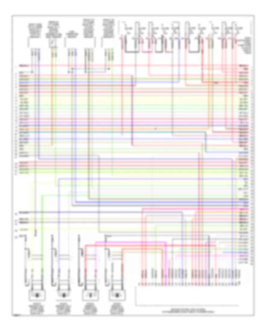
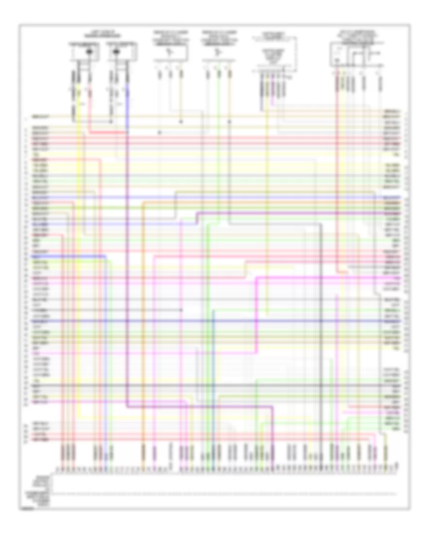
4.2L, Engine Performance Wiring Diagram (3 of 5) for Audi A8 L Quattro 2007
List of elements for 4.2L, Engine Performance Wiring Diagram (3 of 5) for Audi A8 L Quattro 2007:
- (front of cylinder bank no 1) intake manifold runner position sensor
- (front of cylinder bank no 2) intake manifold runner position sensor 2
- (rear of cylinder bank no 1) engine coolant temperature (ect) sensor
- (right side of cylinder bank no 1) camshaft position sensor 3
- 31a nca
- 38a nca
- Engine control module (ecm) (in passenger's side plenum chamber e-box)
- Fuel pressure sensor
- Fuse 10a
- Fuse 15a
- Fuse 30a
- Fuse 40a
- Fuse 5a
- Knock sensor (ks) 1 (inner side of cylinder bank no 1)
- Knock sensor (ks) 2 (inner side of cylinder bank no 1)
- Knock sensor 3 (inner side of cylinder bank no 2)
- Knock sensor 4 (inner side of cylinder bank no 2)
- Nca
- Partial
- Red
- Right instrument panel fuse panel (in right end of dash)
- T60
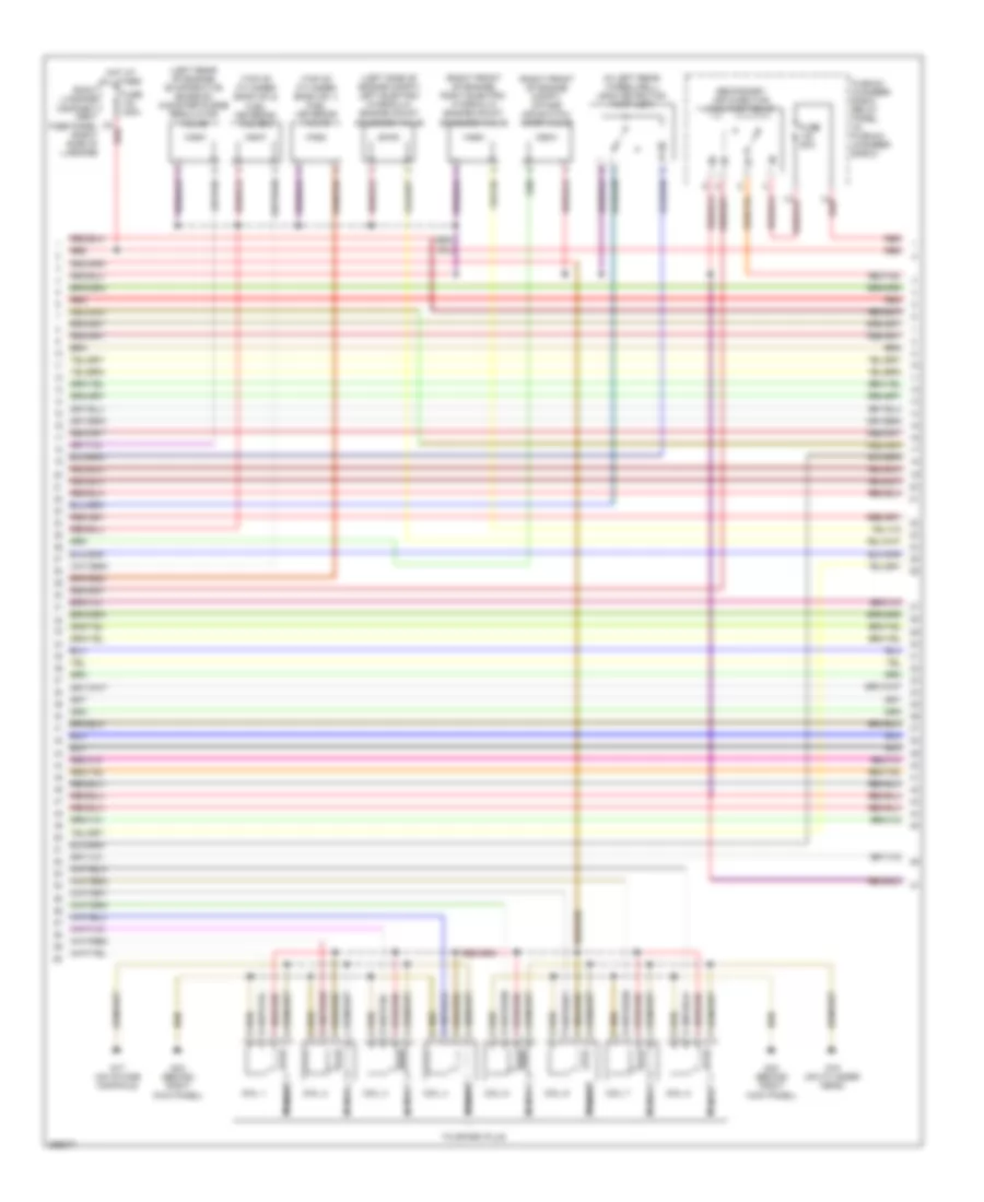
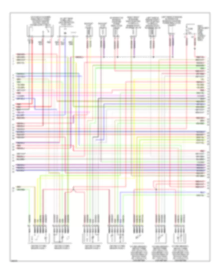
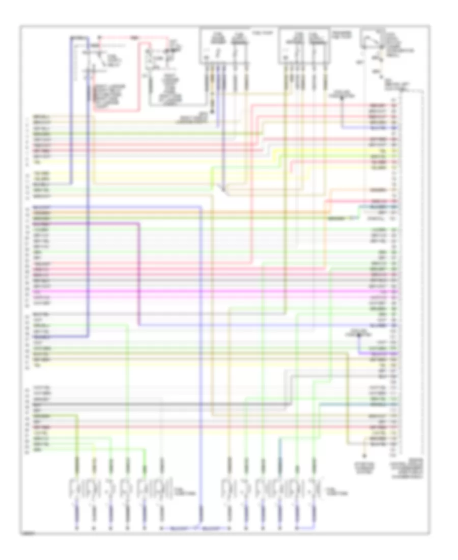
4.2L, Engine Performance Wiring Diagram (4 of 5) for Audi A8 L Quattro 2007
List of elements for 4.2L, Engine Performance Wiring Diagram (4 of 5) for Audi A8 L Quattro 2007:
- (in left rear wheelwell) leak detection pump (ldp)
- (left rear of engine) evaporative emission canister purge regulator valve
- (left side of engine compt) left electro- hydraulic engine mount solenoid valve
- (right front of engine compt) intake air switch- over valve
- (right front of engine) right electro- hydraulic engine mount solenoid valve
- (top of cylinder bank no 1) fuel metering valve
- (top of cylinder bank no 2) fuel metering valve 2
- 1a red
- 3a red
- Coil 1
- Coil 2
- Coil 3
- Coil 4
- Coil 5
- Coil 6
- Coil 7
- Coil 8
- Fuse 150a
- Fuse 50a
- G15 (on cylinder head)
- G17 (on intake manifold)
- G43 (behind right kick panel)
- Hot at all times
- Nca
- Plenum chamber e-box relay panel (in plenum chamber e-box)
- Red
- Right luggage compart- ment fuse panel (right side of luggage
- Secondary air injection (air) pump relay
- To spark plug
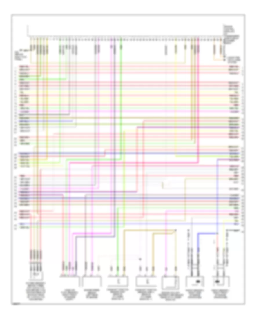
4.2L, Engine Performance Wiring Diagram (5 of 5) for Audi A8 L Quattro 2007
List of elements for 4.2L, Engine Performance Wiring Diagram (5 of 5) for Audi A8 L Quattro 2007:
- Brake booster relay
- Brake system vacuum pump
- Computer data lines system
- Cooling fans system (fuse 17)
- Engine control module (ecm) (in passenger's side plenum chamber e-box)
- Engine speed (rpm) sensor (left rear of engine)
- Evaporative emission canister purge solenoid valve 2 (left rear of engine)
- Fuel injectors
- G43 (behind right kick panel)
- Partial
- Plenum chamber e-box relay panel (in plenum chamber e-box)
- Red
- Secondary air injection (air) pump motor (between right front bumper & wheelwell line)
- Starting/ charging system
- T60
- T94
- Throttle valve control module (behind intake manifold, on throttle valve housing)
6.0L
6.0L, Engine Performance Wiring Diagram (1 of 7) for Audi A8 L Quattro 2007
List of elements for 6.0L, Engine Performance Wiring Diagram (1 of 7) for Audi A8 L Quattro 2007:
- (in plenum chamber e-box) plenum chamber e-box relay panel
- (partial)
- (under left side of dash) data link connector
- 12a
- 22a
- 3a red
- A17
- Access/start control module (under driver's seat)
- Anti-lock brakes system
- Brake light switch
- Computer data lines system
- Cooling fans system
- Cruise control system
- Engine control module (in passenger's side plenum chamber e-box)
- Evaporative emission canister purge solenoid valve (left rear of engine)
- Exterior lights system
- Fuse 150a
- Fuse 30a
- Fuse 5a
- G43 (behind right kick panel)
- G44 (behind left kick panel)
- Hot at all times
- Left instrument panel fuse panel (behind left side of dash)
- Mass air flow sensor (left front of engine compt)
- Red
- Right instrument panel fuse panel (right end of dash)
- Right luggage compartment fuse panel (right side of luggage compt)
- Secondary air injection pump motor (in lower part of air filter housing)
- Secondary air injection pump relay
- Secondary air pump fuse 50a
- Starting/ charging system
- T81
- Throttle position sensor (on accelerator pedal)
- Transmission controls system
- Transmissions system
6.0L, Engine Performance Wiring Diagram (2 of 7) for Audi A8 L Quattro 2007
List of elements for 6.0L, Engine Performance Wiring Diagram (2 of 7) for Audi A8 L Quattro 2007:
- (in left rear wheelwell) leak detection pump (ldp)
- (left rear of engine) evaporative emission canister purge regulator valve 2
- (left side of engine compt) left electro- hydraulic engine mount solenoid valve
- (right front of engine) right electro- hydraulic engine mount solenoid valve
- Behind three way catalytic converter (twc) (downstream of exhaust bank no. 2 catalytic converter)
- Converter)
- Evaporative emission canister purge regulator valve
- Exhaust flap valve 1
- Exhaust flap valve 2
- Fuse 10a
- Heated oxygen sensor (ho2s) 1
- Heated oxygen sensor (ho2s) 2
- Heated oxygen sensor (ho2s) 3
- Heated oxygen sensor (ho2s) 4
- Nca
- Oxygen sensor 1 behind three way catalytic converter (twc) (downstream of exhaust bank no. 1 catalytic
- Oxygen sensor 2
- Oxygen sensor 4 behind three way catalytic converter (twc) (downstream of exhaust bank no. 4 catalytic converter)
- Red
- Right instrument panel fuse panel (in right end of dash)
6.0L, Engine Performance Wiring Diagram (3 of 7) for Audi A8 L Quattro 2007
List of elements for 6.0L, Engine Performance Wiring Diagram (3 of 7) for Audi A8 L Quattro 2007:
- (partial)
- Camshaft position sensor (cmp) (rear of cylinder bank no. 2)
- Camshaft position sensor (cmp) 3 (rear of cylinder bank no. 1)
- Computer data lines system
- Engine control module 2 (in passenger's side plenum t81a chamber e-box)
- Engine coolant temperature sensor (rear of cylinder bank no)
- Engine speed sensor (left rear of engine)
- G43 (behind right kick panel)
- Knock sensor 1 (right front of engine crankcase)
- Knock sensor 2 (right side of engine crankcase)
- Mass air flow sensor 2 (right front of engine compt)
- Nca
- Oxygen sensor 3 behind three way catalytic converter (twc) (downstream of exhaust bank no. 3 catalytic converter)
- Red
6.0L, Engine Performance Wiring Diagram (4 of 7) for Audi A8 L Quattro 2007
List of elements for 6.0L, Engine Performance Wiring Diagram (4 of 7) for Audi A8 L Quattro 2007:
- (2006 models only)
- (center rear of engine) map controlled engine cooling thermostat
- (rear of cylinder bank no. 1) camshaft adjustment valve 1
- (rear of cylinder bank no. 1) camshaft adjustment valve 1 (exhaust)
- (rear of cylinder bank no. 2) camshaft adjustment valve 2
- (rear of cylinder bank no. 2) camshaft adjustment valve 2 (exhaust)
- 28a
- 29a
- 31a
- Fuel pump pump relay (on right kick panel relay & fuse panel)
- Fuse 15a
- Fuse 20a
- Fuse 5a
- G43 (behind right kick panel)
- G600 (on right cylinder head)
- Ignition coil 1
- Ignition coil 2
- Ignition coil 3
- Ignition coil 4
- Ignition coil 5
- Ignition coil 6
- Nca
- Plug spark
- Red
- Right instrument panel fuse panel (in right end of dash)
- Spark plug
- Torque support valve
6.0L, Engine Performance Wiring Diagram (5 of 7) for Audi A8 L Quattro 2007
List of elements for 6.0L, Engine Performance Wiring Diagram (5 of 7) for Audi A8 L Quattro 2007:
- (in plenum chamber e-box) plenum chamber e-box relay panel
- (on cylinder bank no. 2 throttle body) throttle valve control module 2
- G43 (behind right kick panel)
- G44 (behind left kick panel)
- G600 (on right cylinder head)
- Ignition coil 10
- Ignition coil 11
- Ignition coil 12
- Ignition coil 7
- Ignition coil 8
- Ignition coil 9
- Nca
- Plug spark
- Red
- Secondary air injection pump motor 2 (in lower air part of filter housing)
- Secondary air injection pump relay 2
- Secondary air pump fuse 50a
- Spark plug
6.0L, Engine Performance Wiring Diagram (6 of 7) for Audi A8 L Quattro 2007
List of elements for 6.0L, Engine Performance Wiring Diagram (6 of 7) for Audi A8 L Quattro 2007:
- (left side of engine crankcase)
- (on cylinder bank no. 1 throttle body) throttle valve control module
- (partial)
- (rear of cylinder bank no.1) camshaft position sensor (cmp) 2
- (rear of cylinder bank no.2) camshaft position sensor (cmp) 4
- Engine control module 2 (in passenger's side plenum chamber e-box)
- Instrument cluster
- Instrument cluster display unit
- Knock sensor 3
- Knock sensor 4
- Nca
- Red
- T32
- T40a
- T81a
6.0L, Engine Performance Wiring Diagram (7 of 7) for Audi A8 L Quattro 2007
List of elements for 6.0L, Engine Performance Wiring Diagram (7 of 7) for Audi A8 L Quattro 2007:
- (partial)
- Compt relay & fuse panel (right side of luggage compt
- Cooling fans system
- Engine control module (in passenger's side plenum chamber e-box)
- Fuel gauge sender
- Fuel injectors
- Fuel level sensor 2
- Fuel pump
- Fuel pump 2 relay
- Fuse 20a
- G44 (behind left kick panel)
- G675 (right side of luggage compt)
- Hot at all times
- Kick down switch (under accelerator pedal)
- Red
- Right luggage compt fuse panel (right side of luggage compt)
- Starting/ charging system
- T40
- T81
- Transfer fuel pump

 Čeština
 Dansk
Dansk Deutsch
 Ελληνικά
 English
 English
 Español
 Suomi
Suomi Français
 עברית
עברית Hrvatski
 Magyar
 Italiano
 日本語
日本語 한국어
한국어 Nederlands
 Polski
 Português
 Português
 Română
 Русский
 Slovenčina
 Slovenščina
 Svenska
 Türkçe
 中文 (中国)